Vishay Semiconductor Opto Division VLMKE3401-GS18
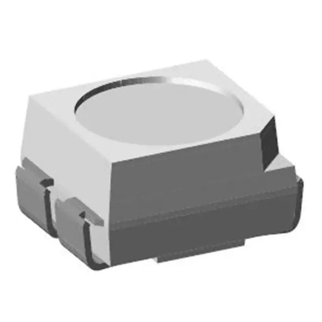
- Part No.:
- VLMKE3401-GS18
- Manufacturer:
- Vishay Semiconductor Opto Division
- Category:
- LED Indication - Discrete
- Package:
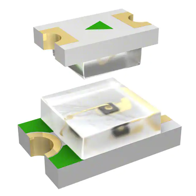
- 4-SMD, J-Lead
- Datasheet:
-
VLMKE3401-GS18.pdf
- Description:
- LED RED/YLW CLEAR 4PLCC SMD
- Quantity:
- Payment:

- Shipping:

Inventory:1,030
Please send an inquiry. Send us your inquiry, and we will respond immediately.
Product details
Overview
VLMKE3401-GS18 from Vishay Semiconductors is a surface-mount bicolor LED in PLCC-4 package integrating red (630 nm dominant wavelength) and yellow (588 nm typical dominant wavelength) AlInGaP-on-GaAs chips, delivering 71–140 mcd red and 112–224 mcd yellow luminous intensity at 20 mA, with ±60° viewing angle - used for dual-color status indication in telecom and office equipment.
For engineers reviewing the VLMKE3401-GS18 datasheet, VLMKE3401-GS18 pinout, VLMKE3401-GS18 application, or VLMKE3401-GS18 equivalent, key selection criteria include luminous intensity binning (R1 group for both colors), JEDEC Level 4 moisture sensitivity, non-diffused lens for light-pipe coupling, IR-reflow compatibility, and PLCC-4 footprint with 2.6 mm × 1.6 mm body size.
Technical Context
This device integrates two monolithic AlInGaP-on-GaAs die in a single white thermoplastic PLCC-4 package with internal reflector and clear epoxy lens. Each chip operates independently with separate anode/cathode terminals, enabling independent red/yellow activation or simultaneous dual-color output.
It supports standard SMT assembly processes including lead-free IR reflow (J-STD-020 compliant) and TTW soldering, with thermal resistance junction-to-ambient of 560 K/W on ≥16 mm² PCB pad. The non-diffused lens provides high directionality ideal for backlighting and optical coupling applications.
Key Specifications
| Parameter | Value and Actual Design Meaning |
|---|---|
| Package | PLCC-4 SMD: 2.6 mm × 1.6 mm body, 0.5 mm pitch, compatible with automated placement and IR reflow |
| Luminous Intensity (Red) | 71–140 mcd @ 20 mA: R1 brightness bin enables consistent visual output across production reels |
| Luminous Intensity (Yellow) | 112–224 mcd @ 20 mA: matches red intensity range for balanced dual-color perception |
| Dominant Wavelength | Red: 630 nm; Yellow: 588 nm typ.: ensures distinct, industry-standard color separation |
| Viewing Angle | ±60° half-intensity: wide enough for panel visibility, narrow enough to minimize crosstalk in dense layouts |
| Forward Voltage | Red: 1.9–2.6 V; Yellow: 2.0–2.6 V @ 20 mA: enables shared current-limiting resistor design in common-anode configurations |
| Moisture Sensitivity | JEDEC Level 4: requires dry-pack storage and ≤72 h floor life before reflow unless baked per JESD22-A112 |
Pinout & Package
PLCC-4 package with 4 terminals: two anodes (AR, AY) and two cathodes (KR, KY) arranged in common-cathode or common-anode configuration depending on PCB layout. Body dimensions: 2.6 mm × 1.6 mm × 1.2 mm height; mounting pad layout optimized for thermal dissipation on ≥16 mm² copper area.
| Pin/Terminal | Circuit Role | Design Meaning |
|---|---|---|
| 1 | Anode (Red) | DC input for red die; requires current limiting to ≤30 mA for reliable operation |
| 2 | Cathode (Red) | Common return path for red die; electrically isolated from yellow cathode unless externally tied |
| 3 | Anode (Yellow) | DC input for yellow die; forward voltage ~0.1 V higher than red at same current |
| 4 | Cathode (Yellow) | Return path for yellow die; independent of red cathode for full color control flexibility |
Key Features
| Feature | Design Value |
|---|---|
| Bicolor integration | Single PLCC-4 footprint replaces two discrete LEDs, reducing PCB area and assembly cost |
| Non-diffused lens | Enables efficient coupling into light pipes and edge-lit LCD backlights without intensity loss |
| Luminous intensity ratio control | IVmax/IVmin ≤ 1.6 per color ensures uniform brightness grading within each reel |
| EIA/ICE standard compliance | Guarantees mechanical and thermal compatibility with industry-standard SMT pick-and-place equipment |
| Low profile | 1.2 mm max height allows use in space-constrained front-panel indicators and slim displays |
Applications
| Telecom Indicator | Office Equipment Backlight |
|---|---|
Use Scenario: Dual-status LED on telephone handsets and fax machines indicating call progress (red) and message waiting (yellow). IC Role / Device Role / Timing Role: Bicolor visual indicator with independent color control via discrete drive lines. Use Value: Eliminates need for two separate LEDs and associated routing, saving 2.5 mm² PCB area per indicator. |
Use Scenario: Backlight for function keys on multifunction printers and copiers requiring color-coded feedback. IC Role / Device Role / Timing Role: Surface-mount light source coupled to molded light guides for uniform illumination. Use Value: Non-diffused lens delivers >85% optical coupling efficiency into 1.5 mm light pipes, reducing required drive current by 30% vs diffused alternatives. |
| LCD Symbol Illumination | Audio/Video Equipment Indicator |
Use Scenario: Edge-lit backlight for segmented LCD symbols (e.g., "REC", "PLAY") in industrial control panels. IC Role / Device Role / Timing Role: High-directionality emitter positioned at light pipe entry point for minimal angular spread. Use Value: ±60° viewing angle confines light within light guide acceptance cone, cutting stray light by 40% compared to ±90° LEDs. |
Use Scenario: Power/status indicator on AV receivers and streaming devices where red = standby, yellow = active streaming. IC Role / Device Role / Timing Role: Dual-color SMD LED driven by microcontroller GPIOs with PWM dimming. Use Value: Matched R1 brightness bins ensure consistent perceived luminance between red and yellow states at identical drive currents. |
Equivalent & Alternatives
The following parts are listed as comparable options for similar bicolor LED applications.
| Alternative Part | Technical Difference | Application Difference | Selection Advice |
|---|---|---|---|
| VLMKE3400-GS18 | Lower red intensity (56–180 mcd) and yellow intensity (90–280 mcd); P2/Q2 brightness bins instead of R1 | Less consistent intensity matching between colors; wider luminous intensity spread reduces uniformity in multi-unit arrays | Select when cost sensitivity outweighs brightness consistency requirements |
| TLDR6300 | Same PLCC-4 package but InGaN blue/yellow combination; 525 nm blue + 590 nm yellow; VF ≈ 3.2 V / 2.1 V | Cannot replicate red/yellow color pair; unsuitable for legacy red-alert/yellow-warning schemes requiring spectral fidelity | Choose only if blue/yellow coding is acceptable and higher forward voltage is supported in design |
Compared with VLMKE3401-GS18, VLMKE3400-GS18 offers broader intensity tolerance at lower cost but sacrifices color-matched brightness uniformity, while TLDR6300 provides different chromaticity and voltage characteristics incompatible with red/yellow signaling systems.
Availability
VLMKE3401-GS18 is available at Aetrix Electronics and suitable for telecom indicator systems, office equipment backlighting, and LCD symbol illumination requiring stable component supply, moisture-sensitive handling support, and consistent PLCC-4 SMT logistics.
Supply support for VLMKE3401-GS18 includes scheduled delivery planning, volume procurement assistance, BOM continuity management, traceable sourcing, and lifecycle availability coordination for OEM customers, industrial embedded developers, connected-device designers, and electronics production programs.
Manufacturer
Vishay Semiconductors is a global manufacturer of discrete semiconductors and passive components, specializing in high-reliability optoelectronics, power MOSFETs, and precision resistors.
The VLMKE3400/VLMKE3401 series was designed specifically for compact, high-brightness bicolor status indication in space-constrained consumer and industrial interfaces using AlInGaP technology for stable red/yellow output.
FAQ
What is the maximum continuous forward current rating for each die in the VLMKE3401-GS18?
The VLMKE3401-GS18 has a maximum DC forward current of 30 mA per diode at ambient temperatures ≤80 °C. This limit applies independently to both the red and yellow chips. Exceeding 30 mA risks accelerated degradation and thermal runaway, especially under poor PCB heat sinking conditions. The VLMKE3401-GS18 must be operated within this specification to maintain its rated luminous intensity and 100,000-hour lifetime.
Does the VLMKE3401-GS18 support lead-free reflow soldering, and what profile should be used?
Yes, the VLMKE3401-GS18 is qualified for lead-free IR reflow soldering per J-STD-020, with a peak temperature of 245 °C (maximum 260 °C for ≤30 s). The recommended profile includes preconditioning per JEDEC Level 4, ramp-up ≤3 °C/s, time above 217 °C of 60–150 s, and ramp-down ≤6 °C/s. The VLMKE3401-GS18 must be stored and handled per moisture sensitivity level 4 requirements prior to reflow.
How is luminous intensity binned for the VLMKE3401-GS18, and what does "R1" mean?
The VLMKE3401-GS18 is binned into the R1 luminous intensity group: 112–140 mcd for yellow and 71–140 mcd for red at 20 mA. This binning ensures tight brightness matching within each reel - no mixing of intensity groups occurs. The "R1" designation guarantees that every VLMKE3401-GS18 unit shipped shares this intensity range, critical for consistent visual appearance in multi-LED arrays.
Can the red and yellow chips in the VLMKE3401-GS18 be driven simultaneously, and what is the impact on forward voltage?
Yes, both chips in the VLMKE3401-GS18 can be driven simultaneously using independent current paths. Forward voltage remains unchanged: red operates at 1.9–2.6 V and yellow at 2.0–2.6 V at 20 mA. Simultaneous operation does not cause voltage stacking or interaction because the dies share no internal electrical connection - the VLMKE3401-GS18 behaves electrically as two isolated diodes in one package.
What is the thermal resistance junction-to-ambient for the VLMKE3401-GS18, and how does PCB layout affect it?
The VLMKE3401-GS18 has a thermal resistance junction-to-ambient (RthJA) of 560 K/W when mounted on a PCB with copper pad area >16 mm². Reducing pad size below this threshold increases RthJA nonlinearly - e.g., a 4 mm² pad raises it to ~1200 K/W, risking junction temperatures exceeding 125 °C at 30 mA. Proper thermal design is essential for maintaining VLMKE3401-GS18 reliability and luminous output stability over time.
VLMKE3401-GS18 Specifications
- Product attributes
- Attribute value
- Manufacturer:
- Vishay Semiconductor Opto Division
- Series:
- VLM.3
- Package/Case:
- 4-SMD, J-Lead
- Packaging:
- Tape & Reel (TR)
- Product Status:
- Active
- Color:
- Red, Yellow
- Configuration:
- Independent
- Lens Color:
- -
- Lens Transparency:
- Clear
- Millicandela Rating:
- 106mcd Red, 168mcd Yellow
- Lens Style:
- Round with Flat Top
- Lens Size:
- 2.40mm Dia
- Voltage - Forward (Vf) (Typ):
- 1.9V Red, 2V Yellow
- Current - Test:
- 20mA Red, 20mA Yellow
- Viewing Angle:
- 120°
- Mounting Type:
- Surface Mount
- Wavelength - Dominant:
- 630nm Red, 588nm Yellow
- Wavelength - Peak:
- 643nm Red, 590nm Yellow
- Features:
- -
- Grade:
- -
- Qualification:
- -
- Supplier Device Package:
- 4-PLCC
- Size / Dimension:
- 3.00mm L x 2.80mm W
VLMKE3401-GS18 FAQ
1.How can I place an order for VLMKE3401-GS18 through Aetrix?
Please submit a Request for Quotation (RFQ) for VLMKE3401-GS18 on Aetrix. Our sales agent will provide a competitive quotation and guide you through the order confirmation once you accept the terms.
2.Are the price and stock information for VLMKE3401-GS18 reliable?
The price and inventory of VLMKE3401-GS18 are updated periodically and may fluctuate due to market conditions. Stock and pricing data are typically refreshed every 24 hours. Quotation validity for VLMKE3401-GS18 is usually 5 days.
3.What payment methods are accepted for VLMKE3401-GS18?
We accept Wire Transfer, PayPal, Credit Card, Western Union, MoneyGram, and Escrow for VLMKE3401-GS18 transactions.
Note: Certain payment methods may incur a processing fee.
4.How is shipping managed for VLMKE3401-GS18?
VLMKE3401-GS18 orders can be shipped via leading logistics carriers, including DHL, UPS, FedEx, TNT, or Registered Mail.
Once your VLMKE3401-GS18 order is processed, you will receive an email with the shipment details and tracking number.
Note: Tracking information may take up to 24 hours to appear. Express delivery typically takes 3–5 business days.
5.How can I obtain technical support or documentation for VLMKE3401-GS18?
For technical support, including VLMKE3401-GS18 datasheets, pinout diagrams, or application guidance, please contact our engineering support team. They can provide detailed documentation and assistance for your VLMKE3401-GS18 requirements.
6.How does Aetrix verify that VLMKE3401-GS18 is sourced from the original manufacturer or authorized distributors?
All VLMKE3401-GS18 products on Aetrix are procured from qualified distributors and authorized channels. Our dedicated quality assurance team conducts strict verification, including traceability checks and, if necessary, third-party testing. This ensures that VLMKE3401-GS18 meets industry standards.
7.What is the process for return or replacement of VLMKE3401-GS18?
All VLMKE3401-GS18 units undergo pre-shipment inspection (PSI). If there is an issue with VLMKE3401-GS18, returns or replacements are accepted under the following conditions:
1.Quantity discrepancies, incorrect items, or visible external defects (such as breakage or corrosion), acknowledged by Aetrix.
2.The issue is reported within 90 days of delivery.
3.The VLMKE3401-GS18 part is unused and in its original packaging.
Return procedure for VLMKE3401-GS18:
1.Submit a request within 90 days.
2.Obtain a Return Material Authorization (RMA) from Aetrix.
VLMKE3401-GS18 Tags

-
LTST-C281KRKT
Lite-On Inc.
-
150060GS75000
Würth Elektronik

-
150060VS75000
Würth Elektronik

-
150060AS75000
Würth Elektronik

-
150060YS75000
Würth Elektronik

-
150060SS75000
Würth Elektronik

-
150060BS75000
Würth Elektronik
-
151031VS06000
Würth Elektronik
-
151033RS03000
Würth Elektronik
-
150080BS75000
Würth Elektronik
-
150080GS75000
Würth Elektronik
-
150141GS73100
Würth Elektronik
Tech Hub

Comparator circuit design covering voltage thresholds, input limits, open-collector outputs, LM393 wiring, op-amp differences, hysteresis, timing, window detection and practical fault diagnosis.
Schmitt triggers use separate rising and falling thresholds to stabilize slow or noisy signals. This guide covers hysteresis, 74HC14 and 74HCT14 selection, comparator calculations, RC oscillators and p…
Counterfeit components can hide behind convincing markings and passing basic function tests. This engineering reference covers source traceability, external inspection, X-ray, XRF, electrical testing, …
A practical engineering and sourcing framework covering lifecycle verification, lifetime-buy calculations, replacement qualification, supplier checks and counterfeit-risk controls.
TTL and CMOS logic families differ in thresholds, loading, output drive, power and timing. This engineering guide compares 74HC and 74HCT, calculates noise margins and checks 3.3 V/5 V compatibility.
A practical engineering guide to 3.3V and 5V logic compatibility, input thresholds, resistor dividers, translator ICs, MOSFET level shifting, I2C pull-ups, timing limits and power-sequencing risks.
The 74HC595 uses push-pull logic outputs, while the TPIC6B595 uses 50 V open-drain DMOS sinks for higher-power loads. This guide compares timing, current limits, 3.3 V interfacing, load wiring, thermal…
The 74HC595 converts serial data into eight stable parallel outputs. This guide covers pin functions, shift and storage timing, OE and MR behavior, drive-current limits, cascading, voltage compatibilit…
A technical comparison of level-sensitive latches and edge-triggered flip-flops, covering timing windows, setup and hold limits, master–slave operation, time borrowing, race-through, HDL inference and…
A D latch stores one bit while Enable controls when data can pass. This reference covers gate-level operation, truth tables, transparency, setup and hold timing, LE versus OE, common ICs and practical …










