Vishay Semiconductor Opto Division VOW2611-X017T
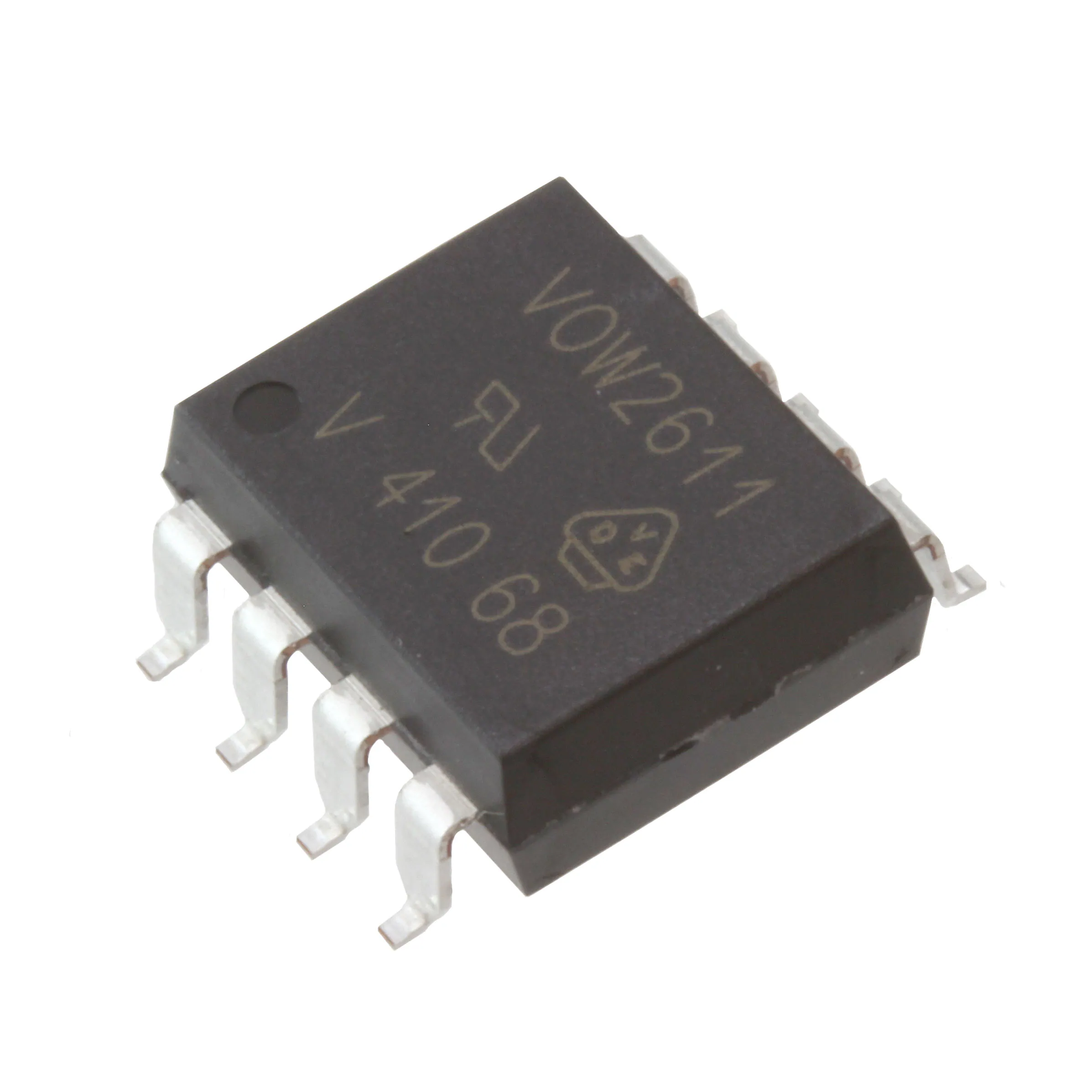
- Part No.:
- VOW2611-X017T
- Manufacturer:
- Vishay Semiconductor Opto Division
- Category:
- Logic Output Optoisolators
- Package:
- 8-SMD, Gull Wing
- Datasheet:
-
VOW2611-X017T.pdf
- Description:
- OPTOISO 5.3KV OPN COLLECTOR 8SMD
- Quantity:
- Payment:

- Shipping:

Inventory:498
Please send an inquiry. Send us your inquiry, and we will respond immediately.
Product details
Overview
VOW2611-X017T from Vishay Semiconductors is a high-speed optocoupler with 10 MBd data rate, strobable open-drain output, and guaranteed common-mode transient immunity of 10 kV/μs. It features LVTTL/LVCMOS compatibility, operates from 4.5 V to 5.5 V supply, and delivers propagation delays as low as 25 ns (tPLH/tPHL) for digital isolation in industrial power supplies and microprocessor interfaces.
For engineers reviewing the VOW2611-X017T datasheet, VOW2611-X017T pinout, VOW2611-X017T application, or VOW2611-X017T equivalent, key selection criteria include CMTI ≥10 kV/μs, isolation voltage rating of 5000 VRMS, open-drain output configuration, operating temperature range of –40 °C to +100 °C, and SMD-8 widebody package with 10 mm creepage/clearance.
Technical Context
The VOW2611-X017T integrates a high-efficiency GaAs LED input stage coupled to a monolithic photodetector logic gate with strobe-enabled control. Its internal shield ensures robust noise rejection in high dv/dt environments such as motor drives and isolated DC-DC converters.
It supports positive-logic truth table operation with enable-controlled output latching, offers 1 pF input-to-output capacitance for minimal signal coupling, and maintains stable switching performance across –40 °C to +100 °C with typical pulse width distortion under 10 ns.
Key Specifications
| Parameter | Value and Actual Design Meaning |
|---|---|
| Data rate | 10 MBd - supports high-speed serial communication links without external buffering |
| CMTI | ≥10 kV/μs - prevents false triggering in noisy industrial environments with fast transients |
| Isolation voltage | 5000 VRMS - meets UL1577 and enables safe operation at >1000 V working voltage |
| Propagation delay | 25–100 ns - ensures timing-critical digital isolation in real-time control loops |
| Supply voltage | 4.5–5.5 V - compatible with standard 5 V logic systems and LVTTL/LVCMOS interfaces |
| Output type | Open-drain - allows flexible pull-up configuration and wired-OR bus interfacing |
| Operating temp. | –40 °C to +100 °C - qualified for extended industrial and automotive under-hood applications |
Pinout & Package
SMD-8, 400 mil widebody package with 10.12 mm body width, 12.30 mm length, and ≥10 mm creepage/clearance distance. RoHS-compliant, moisture sensitivity level 1.
| Pin/Terminal | Circuit Role | Design Meaning |
|---|---|---|
| 1 (ANODE) | LED anode input | Connects to current-limited digital source; requires series resistor for IF = 5–15 mA operation |
| 2 (CATHODE) | LED cathode return | Ground reference for input LED; defines forward bias polarity |
| 3 (VE) | Enable control input | Active-high strobe: logic high enables output, logic low forces high-Z output state |
| 4 (GND) | Output ground reference | Common return for VCC and output load; must be isolated from input ground |
| 5 (VCC) | Output supply rail | Provides power to photodetector logic; decoupling capacitor required at pin |
| 6 (VO) | Open-drain output | Sinks current when active low; requires external pull-up for logic high level |
| 7 (NC) | No connect | Internally unconnected; must remain floating or tied to GND per layout best practice |
| 8 (NC) | No connect | Internally unconnected; must remain floating or tied to GND per layout best practice |
Key Features
| Feature | Design Value |
|---|---|
| Strobable output control | VE pin enables precise timing-gated data capture, eliminating metastability in synchronous isolation |
| High CMTI shielding | Internal Faraday shield guarantees ≥10 kV/μs immunity-critical for IGBT gate driver feedback in inverters |
| LVTTL/LVCMOS compatibility | Input threshold (ITH = 2–5 mA) and output VOL ≤ 0.6 V at 13 mA ensure direct interface with 3.3 V/5 V logic families |
| Low inter-channel capacitance | 1 pF CIO minimizes capacitive coupling noise across isolation barrier, preserving signal integrity |
| Wide operating temperature | –40 °C to +100 °C range supports deployment in harsh environments including industrial PLCs and solar inverters |
Applications
| Microprocessor System Interface | Digital Bus Isolation |
|---|---|
Use Scenario: Isolating UART, SPI, or GPIO signals between MCU and high-voltage peripherals in programmable logic controllers. IC Role / Device Role / Timing Role: Bidirectional digital isolator with strobe-controlled output enabling synchronized data sampling during critical control cycles. Use Value: Prevents ground loop corruption and enables reliable firmware updates over isolated debug channels at up to 10 MBd. | Use Scenario: Segmenting CAN or RS-485 bus domains in factory automation networks to contain fault propagation. IC Role / Device Role / Timing Role: Unidirectional data isolator with open-drain output supporting multi-drop wired-OR bus topologies. Use Value: Maintains signal edge fidelity (tr/tf ≤ 23/10 ns) while blocking common-mode transients up to 10 kV/μs on shared bus lines. |
| High-Speed A/D Conversion | Digital Control Power Supply |
Use Scenario: Isolating conversion-ready strobes and data lines between isolated ADCs and host processors in energy metering systems. IC Role / Device Role / Timing Role: Timing-critical isolator delivering sub-100 ns propagation delay skew (tPSK ≤ 40 ns) for synchronized sample-and-hold control. Use Value: Enables accurate time-aligned acquisition across multiple isolated ADC channels without added jitter or delay mismatch. | Use Scenario: Providing feedback isolation for voltage-mode or current-mode PWM controllers in isolated DC-DC converters. IC Role / Device Role / Timing Role: Fast-response error signal isolator with <100 ns total propagation delay ensuring tight regulation loop bandwidth. Use Value: Supports >500 kHz switching frequencies by minimizing isolation-induced phase lag in control-to-output path. |
Equivalent & Alternatives
The following parts are listed as comparable options for similar high-speed optocoupler applications.
| Alternative Part | Technical Difference | Application Difference | Selection Advice |
|---|---|---|---|
| ACPL-K37T | Higher CMTI (25 kV/μs), same 10 MBd rate, but requires external VDD bypass and has different enable logic polarity | Better suited for ultra-noisy motor drive gate driver feedback where CMTI margin is critical | Select ACPL-K37T only if system-level CMTI requirement exceeds 15 kV/μs and layout allows polarity-aware enable routing |
| HCPL-0723 | Same SMD-8 package and pinout, but lower data rate (5 MBd) and no strobe enable function | Applicable where cost sensitivity outweighs need for strobe control and full 10 MBd bandwidth | Choose HCPL-0723 for legacy designs requiring drop-in replacement without redesigning enable logic or timing constraints |
Compared with VOW2611-X017T, ACPL-K37T provides superior noise immunity but demands careful enable signal inversion and tighter layout controls, while HCPL-0723 sacrifices speed and strobe capability for broader availability and lower unit cost in non-critical timing applications.
Availability
VOW2611-X017T is available at Aetrix Electronics and suitable for industrial automation, renewable energy inverters, and medical diagnostic equipment requiring stable component supply, long-term lifecycle support, and certified isolation performance.
Supply support for VOW2611-X017T includes scheduled delivery planning, volume procurement assistance, BOM continuity management, traceable sourcing, and lifecycle availability coordination for OEM customers, industrial embedded developers, connected-device designers, and electronics production programs.
Manufacturer
Vishay Intertechnology is a global manufacturer of discrete semiconductors and passive components, headquartered in Malvern, PA, with design and manufacturing facilities worldwide.
The VOW2611-X017T belongs to Vishay's high-speed optocoupler product line, engineered specifically for robust digital signal isolation in industrial power electronics, motor control, and safety-critical embedded systems.
FAQ
What is the maximum recommended forward current for the VOW2611-X017T LED input?
The absolute maximum forward current for the VOW2611-X017T LED input is 20 mA, but the recommended operating condition specifies 5–15 mA for reliable long-term performance. Operating at 7.5 mA achieves optimal balance between speed (tPLH/tPHL ≈ 50 ns typ.) and LED lifetime. Exceeding 15 mA continuously may accelerate degradation without improving switching performance.
Does the VOW2611-X017T require an external pull-up resistor on the VO pin?
Yes, the VOW2611-X017T features an open-drain VO output and requires an external pull-up resistor to VCC. The recommended value ranges from 330 Ω to 4000 Ω depending on speed and fanout requirements; 1 kΩ is typical for driving up to five TTL loads while maintaining <100 ns propagation delay. No pull-up is needed on the VE pin, which has internal biasing.
What safety certifications does the VOW2611-X017T hold?
The VOW2611-X017T is certified to UL1577 (5000 VRMS isolation), cUL, and DIN EN 60747-5-5 (VDE 0884-5) with option 1, providing reinforced insulation qualification. It meets creepage and clearance distances ≥10 mm and has a comparative tracking index (CTI) of 175, making it suitable for pollution degree 2 environments per IEC 60664-1.
Can the VOW2611-X017T operate from a 3.3 V supply?
No, the VOW2611-X017T is specified for VCC = 4.5 V to 5.5 V only. Its output logic thresholds (VEL ≤ 0.8 V, VEH ≥ 2 V) and VOL ≤ 0.6 V at 13 mA sink current are optimized for 5 V operation. Using 3.3 V risks violating the minimum VEH requirement and degrading noise margins; for 3.3 V systems, consider Vishay's VO615A or similar 3.3 V-compatible optocouplers instead of VOW2611-X017T.
How does the enable (VE) pin function in the VOW2611-X017T truth table?
The VE pin acts as a positive-logic strobe: when VE is high (≥2 V), the output VO reflects the LED state (low when LED on, high-Z when LED off); when VE is low (≤0.8 V), VO is forced high-Z regardless of LED state. This enables precise timing control-e.g., sampling only during valid data windows-without requiring additional logic gates or clock synchronization circuitry in the VOW2611-X017T design.
VOW2611-X017T Specifications
- Product attributes
- Attribute value
- Manufacturer:
- Vishay Semiconductor Opto Division
- Series:
- -
- Package/Case:
- 8-SMD, Gull Wing
- Packaging:
- Tape & Reel (TR)
- Product Status:
- Obsolete
- Number of Channels:
- 1
- Inputs - Side 1/Side 2:
- 1/0
- Voltage - Isolation:
- 5300Vrms
- Common Mode Transient Immunity (Min):
- 25kV/µs
- Input Type:
- DC
- Output Type:
- Open Collector
- Current - Output / Channel:
- 50 mA
- Data Rate:
- 10MBd
- Propagation Delay tpLH / tpHL (Max):
- 100ns, 100ns
- Rise / Fall Time (Typ):
- 14ns, 7ns
- Voltage - Forward (Vf) (Typ):
- 1.4V
- Current - DC Forward (If) (Max):
- 20mA
- Voltage - Supply:
- 4.5V ~ 5.5V
- Grade:
- -
- Qualification:
- -
- Operating Temperature:
- -40°C ~ 100°C
- Mounting Type:
- Surface Mount
- Supplier Device Package:
- 8-SMD
VOW2611-X017T FAQ
1.How can I place an order for VOW2611-X017T through Aetrix?
Please submit a Request for Quotation (RFQ) for VOW2611-X017T on Aetrix. Our sales agent will provide a competitive quotation and guide you through the order confirmation once you accept the terms.
2.Are the price and stock information for VOW2611-X017T reliable?
The price and inventory of VOW2611-X017T are updated periodically and may fluctuate due to market conditions. Stock and pricing data are typically refreshed every 24 hours. Quotation validity for VOW2611-X017T is usually 5 days.
3.What payment methods are accepted for VOW2611-X017T?
We accept Wire Transfer, PayPal, Credit Card, Western Union, MoneyGram, and Escrow for VOW2611-X017T transactions.
Note: Certain payment methods may incur a processing fee.
4.How is shipping managed for VOW2611-X017T?
VOW2611-X017T orders can be shipped via leading logistics carriers, including DHL, UPS, FedEx, TNT, or Registered Mail.
Once your VOW2611-X017T order is processed, you will receive an email with the shipment details and tracking number.
Note: Tracking information may take up to 24 hours to appear. Express delivery typically takes 3–5 business days.
5.How can I obtain technical support or documentation for VOW2611-X017T?
For technical support, including VOW2611-X017T datasheets, pinout diagrams, or application guidance, please contact our engineering support team. They can provide detailed documentation and assistance for your VOW2611-X017T requirements.
6.How does Aetrix verify that VOW2611-X017T is sourced from the original manufacturer or authorized distributors?
All VOW2611-X017T products on Aetrix are procured from qualified distributors and authorized channels. Our dedicated quality assurance team conducts strict verification, including traceability checks and, if necessary, third-party testing. This ensures that VOW2611-X017T meets industry standards.
7.What is the process for return or replacement of VOW2611-X017T?
All VOW2611-X017T units undergo pre-shipment inspection (PSI). If there is an issue with VOW2611-X017T, returns or replacements are accepted under the following conditions:
1.Quantity discrepancies, incorrect items, or visible external defects (such as breakage or corrosion), acknowledged by Aetrix.
2.The issue is reported within 90 days of delivery.
3.The VOW2611-X017T part is unused and in its original packaging.
Return procedure for VOW2611-X017T:
1.Submit a request within 90 days.
2.Obtain a Return Material Authorization (RMA) from Aetrix.
VOW2611-X017T Tags

-
6N137
Lite-On Inc.
-
6N137S
Lite-On Inc.
-
6N137S-TA1
Lite-On Inc.
-
TLP2362(TPR,E
Toshiba Semiconductor and Storage
-
H11L1M
onsemi
-
TLP2355(TPL,E
Toshiba Semiconductor and Storage
-
TLP2361(TPL,E
Toshiba Semiconductor and Storage
-
TLP2358(TPL,E)
Toshiba Semiconductor and Storage
-
H11L1SR2M
onsemi
-
TLP2361(V4-TPL,E
Toshiba Semiconductor and Storage
-
H11L1S(TA)
Everlight Electronics Co Ltd
-
H11L1SM
onsemi
Tech Hub

Comparator circuit design covering voltage thresholds, input limits, open-collector outputs, LM393 wiring, op-amp differences, hysteresis, timing, window detection and practical fault diagnosis.
Schmitt triggers use separate rising and falling thresholds to stabilize slow or noisy signals. This guide covers hysteresis, 74HC14 and 74HCT14 selection, comparator calculations, RC oscillators and p…
Counterfeit components can hide behind convincing markings and passing basic function tests. This engineering reference covers source traceability, external inspection, X-ray, XRF, electrical testing, …
A practical engineering and sourcing framework covering lifecycle verification, lifetime-buy calculations, replacement qualification, supplier checks and counterfeit-risk controls.
TTL and CMOS logic families differ in thresholds, loading, output drive, power and timing. This engineering guide compares 74HC and 74HCT, calculates noise margins and checks 3.3 V/5 V compatibility.
A practical engineering guide to 3.3V and 5V logic compatibility, input thresholds, resistor dividers, translator ICs, MOSFET level shifting, I2C pull-ups, timing limits and power-sequencing risks.
The 74HC595 uses push-pull logic outputs, while the TPIC6B595 uses 50 V open-drain DMOS sinks for higher-power loads. This guide compares timing, current limits, 3.3 V interfacing, load wiring, thermal…
The 74HC595 converts serial data into eight stable parallel outputs. This guide covers pin functions, shift and storage timing, OE and MR behavior, drive-current limits, cascading, voltage compatibilit…
A technical comparison of level-sensitive latches and edge-triggered flip-flops, covering timing windows, setup and hold limits, master–slave operation, time borrowing, race-through, HDL inference and…
A D latch stores one bit while Enable controls when data can pass. This reference covers gate-level operation, truth tables, transparency, setup and hold timing, LE versus OE, common ICs and practical …









