Send an Inquiry

To receive a quote for your project, please fill in the following information, and we’ll get back to you promptly.

Name*
Company*
Email Address*
Phone/WhatsApp
Part Number*
Quantity*
Message
Submit Inventory List

Please fill in the following information, and we’ll get back to you promptly.

Name*
Company*
Email Address*
Phone/WhatsApp
Upload My List
Message

Vishay General Semiconductor - Diodes Division ZPY75-TR

Part No.:
ZPY75-TR
Manufacturer:
Vishay General Semiconductor - Diodes Division
Category:
Single Zener Diodes
Package:
DO-204AL, DO-41, Axial
Datasheet:
AetrixZPY75-TR.pdf
Description:
DIODE ZENER 75V 1.3W DO204AL
Quantity:
Payment:
Payment
Shipping:
Shipping

Inventory:2,306

Please send an inquiry. Send us your inquiry, and we will respond immediately.

Part Number
Quantity*
Price
Name*
Company
Email*
Comments

Product details

Overview

ZPY75-TR from Vishay Semiconductors is a silicon planar power Zener diode rated for 75 V nominal Zener voltage (70–79 V range), 10 mA test current, 1300 mW power dissipation, and 13 Ω dynamic resistance at 1 kHz. It operates with a +8 × 10⁻⁴/°C temperature coefficient and is used in high-stability voltage reference and overvoltage clipping circuits in industrial power supplies.

For engineers reviewing the ZPY75-TR datasheet, ZPY75-TR pinout, ZPY75-TR application, or ZPY75-TR equivalent, key selection considerations include its DO-41 package thermal resistance (110 K/W), admissible Zener current up to 160 mA, and compliance with E12 voltage grading for precision stabilization across ambient temperatures from –55 °C to +175 °C.

Technical Context

This discrete Zener diode functions as a two-terminal voltage reference device, operating in reverse breakdown with tightly controlled VZ tolerance (±6.7% at 75 V) and low dynamic impedance. Its single-diode configuration supports DC stabilization and transient voltage clamping without external biasing.

Designed for operation under pulsed conditions (tp = 10 ms) with leads held at ambient temperature 4 mm from case, it maintains stable regulation up to Tj = 175 °C and meets MSL Level 1 moisture sensitivity per J-STD-020.

Key Specifications

Parameter Value and Actual Design Meaning
Zener Voltage (VZ) 70–79 V range, nominal 75 V - defines precise DC reference or clamping threshold in regulated power rails
Test Current (IZT) 10 mA - standard condition for specifying VZ; ensures measurement repeatability and datasheet comparability
Power Dissipation (Ptot) 1300 mW - maximum steady-state power handling at Tamb = 25 °C with 4 mm lead length cooling
Dynamic Resistance (ZZ) 13 Ω at 1 kHz - indicates low AC impedance for effective ripple suppression in feedback loops
Temperature Coefficient (TCVZ) +8 × 10⁻⁴/°C - positive drift enables predictable compensation in temperature-varying circuits
Junction-to-Ambient Thermal Resistance (RthJA) 110 K/W - determines allowable power derating above 25 °C ambient; critical for thermal design margin
Admissible Zener Current (IZ) 70 mA (max), <160 mA pulse - sets safe continuous and transient current limits for reliability

Pinout & Package

Package: DO-41 (DO-204AL), axial-leaded, epoxy-molded, UL 94 V-0 compliant, ~310 mg weight. Cathode identified by band.

Pin/Terminal Circuit Role Design Meaning
Anode Forward conduction terminal / reference ground node in shunt regulator Connected to lower-potential side of circuit; establishes reference point for Zener voltage drop
Cathode Reverse-biased Zener terminal / regulated output node Banded end; carries regulated voltage relative to anode; must be biased above anode by ≥VZ

Key Features

Feature Design Value
Silicon planar construction Ensures tight VZ tolerance and long-term stability vs. alloy-junction alternatives
E12-standard voltage grading Enables interoperability with standardized resistor/capacitor networks in analog control systems
1300 mW power rating Supports direct shunt regulation in 5–10 W auxiliary supplies without heatsinking
MSL Level 1 rating Permits unlimited floor life and standard reflow without baking or special handling
+8 × 10⁻⁴/°C TCVZ Allows predictable thermal drift modeling in wide-temperature industrial environments

Applications

Industrial Power Supply Reference Overvoltage Protection Clamp

Use Scenario: Stabilizing feedback voltage in isolated flyback or forward converter secondary-side regulation.

IC Role / Device Role / Timing Role: Shunt voltage reference for TL431 or optocoupler-based error amplifiers.

Use Value: Maintains ±1% output accuracy over line/load/temperature with 13 Ω ZZ minimizing loop gain variation.

Use Scenario: Clamping transient surges on 48 V DC bus lines in factory automation I/O modules.

IC Role / Device Role / Timing Role: Passive crowbar element absorbing >100 V spikes before downstream IC damage.

Use Value: Withstands 160 mA peak surge current and dissipates 1300 mW without degradation under repeated 10 ms pulses.

Programmable Logic Controller Input Protection Test Equipment Voltage Calibration Standard

Use Scenario: Protecting 24 V digital input channels against field-wiring faults and inductive kickback.

IC Role / Device Role / Timing Role: Primary clamp limiting input voltage to ≤79 V during fault events.

Use Value: 70–79 V VZ range ensures reliable triggering above normal operating voltage while avoiding false trips.

Use Scenario: Serving as traceable 75 V reference in benchtop multimeter calibration fixtures.

IC Role / Device Role / Timing Role: Stable DC reference source for ADC/DAC linearity verification.

Use Value: E12 grading and ±6.7% tolerance enable repeatable, cross-lab comparable measurements at 75 V point.

Equivalent & Alternatives

The following parts are listed as comparable options for similar Zener diode applications.

Alternative Part Technical Difference Application Difference Selection Advice
1N4745A-T 75 V nominal, 1000 mW Ptot, 15 Ω ZZ, DO-41, ±5% tolerance Lower power rating limits use in high-current clamping; tighter tolerance suits precision references Prefer when board space allows same DO-41 footprint but lower thermal load is expected
BZX85C75 75 V nominal, 1300 mW Ptot, 20 Ω ZZ, DO-41, ±5% tolerance, higher TCVZ (+10 × 10⁻⁴/°C) Higher dynamic resistance reduces ripple rejection; elevated TCVZ increases drift in wide-temp designs Acceptable where cost is prioritized over thermal stability and AC performance

Compared with 1N4745A-T and BZX85C75, ZPY75-TR delivers superior thermal robustness (1300 mW vs. 1000 mW), lower dynamic impedance (13 Ω vs. ≥15 Ω), and optimized temperature coefficient for industrial ambient ranges - making it preferred for high-reliability power rail stabilization.

Availability

ZPY75-TR is available at Aetrix Electronics and suitable for industrial power supply reference, overvoltage protection clamp, and programmable logic controller input protection requiring stable component supply and long-lifecycle support.

Supply support for ZPY75-TR includes scheduled delivery planning, volume procurement assistance, BOM continuity management, traceable sourcing, and lifecycle availability coordination for OEM customers, industrial embedded developers, connected-device designers, and electronics production programs.

Manufacturer

Vishay Intertechnology is a global semiconductor and passive component manufacturer specializing in high-reliability discrete devices and sensors.

ZPY75-TR belongs to Vishay's silicon planar Zener diode family engineered for high-power stabilization and precision voltage clamping in harsh industrial and automotive environments.

FAQ

What is the Zener voltage tolerance for ZPY75-TR?

The ZPY75-TR has a specified Zener voltage range of 70 V to 79 V at 10 mA test current, corresponding to a ±6.7% tolerance around the nominal 75 V value. This tolerance is verified per the Vishay datasheet Rev. 2.4 (Document Number: 85790) and reflects manufacturing spread under standard test conditions. The ZPY75-TR maintains this specification across its qualified operating temperature range.

Can ZPY75-TR be used in surface-mount designs?

No, ZPY75-TR uses the through-hole DO-41 (DO-204AL) axial package and is not compatible with SMT assembly processes. It requires hole mounting and wave or selective soldering. For surface-mount equivalents, consider Vishay's SMAZ75 or similar SOD-123 packages - but note these differ in power rating, thermal resistance, and ZZ. The ZPY75-TR itself is strictly a leaded device.

What is the maximum allowable junction temperature for ZPY75-TR?

The absolute maximum junction temperature for ZPY75-TR is 175 °C, as defined in the Vishay Absolute Maximum Ratings table. Operation beyond this limit risks irreversible degradation of the silicon junction. Derating is required above 25 °C ambient per the Ptot vs. Tamb curve (Fig. 1), and thermal design must ensure RthJA = 110 K/W is respected with proper lead length and PCB copper area.

Does ZPY75-TR meet RoHS and REACH requirements?

Yes, ZPY75-TR complies with RoHS Directive 2011/65/EU and REACH Regulation (EC) No. 1907/2006, as confirmed in Vishay's material declarations (Document Number: 99912). The device uses lead-free terminations and UL 94 V-0 molding compound. Compliance status is maintained across all manufacturing lots, and full substance disclosure is available upon request from Aetrix Electronics.

How does the temperature coefficient affect ZPY75-TR in real-world circuits?

ZPY75-TR exhibits a +8 × 10⁻⁴/°C temperature coefficient, meaning its Zener voltage increases by approximately 60 mV per 10 °C rise in junction temperature. In a 48 V system with 75 V clamping, this results in ~0.08 V/°C drift - critical for designs operating from –40 °C to +85 °C ambient. Engineers must account for this in overvoltage margin calculations, especially where self-heating exceeds 20 °C rise. The ZPY75-TR's predictable TCVZ enables accurate thermal compensation.

ZPY75-TR Specifications

Product attributes
Attribute value
Manufacturer:
Vishay General Semiconductor - Diodes Division
Series:
-
Package/Case:
DO-204AL, DO-41, Axial
Packaging:
Tape & Reel (TR)
Product Status:
Active
Voltage - Zener (Nom) (Vz):
75 V
Tolerance:
±5%
Power - Max:
1.3 W
Impedance (Max) (Zzt):
70 Ohms
Current - Reverse Leakage @ Vr:
500 nA @ 56 V
Voltage - Forward (Vf) (Max) @ If:
-
Operating Temperature:
175°C
Grade:
Automotive
Qualification:
AEC-Q101
Mounting Type:
Through Hole
Supplier Device Package:
DO-204AL (DO-41)

ZPY75-TR FAQ

1.How can I place an order for ZPY75-TR through Aetrix?

Please submit a Request for Quotation (RFQ) for ZPY75-TR on Aetrix. Our sales agent will provide a competitive quotation and guide you through the order confirmation once you accept the terms.

2.Are the price and stock information for ZPY75-TR reliable?

The price and inventory of ZPY75-TR are updated periodically and may fluctuate due to market conditions. Stock and pricing data are typically refreshed every 24 hours. Quotation validity for ZPY75-TR is usually 5 days.

3.What payment methods are accepted for ZPY75-TR?

We accept Wire Transfer, PayPal, Credit Card, Western Union, MoneyGram, and Escrow for ZPY75-TR transactions.

Note: Certain payment methods may incur a processing fee.

4.How is shipping managed for ZPY75-TR?

ZPY75-TR orders can be shipped via leading logistics carriers, including DHL, UPS, FedEx, TNT, or Registered Mail.

Once your ZPY75-TR order is processed, you will receive an email with the shipment details and tracking number.

Note: Tracking information may take up to 24 hours to appear. Express delivery typically takes 3–5 business days.

5.How can I obtain technical support or documentation for ZPY75-TR?

For technical support, including ZPY75-TR datasheets, pinout diagrams, or application guidance, please contact our engineering support team. They can provide detailed documentation and assistance for your ZPY75-TR requirements.

6.How does Aetrix verify that ZPY75-TR is sourced from the original manufacturer or authorized distributors?

All ZPY75-TR products on Aetrix are procured from qualified distributors and authorized channels. Our dedicated quality assurance team conducts strict verification, including traceability checks and, if necessary, third-party testing. This ensures that ZPY75-TR meets industry standards.

7.What is the process for return or replacement of ZPY75-TR?

All ZPY75-TR units undergo pre-shipment inspection (PSI). If there is an issue with ZPY75-TR, returns or replacements are accepted under the following conditions:

1.Quantity discrepancies, incorrect items, or visible external defects (such as breakage or corrosion), acknowledged by Aetrix.

2.The issue is reported within 90 days of delivery.

3.The ZPY75-TR part is unused and in its original packaging.

Return procedure for ZPY75-TR:

1.Submit a request within 90 days.

2.Obtain a Return Material Authorization (RMA) from Aetrix.

ZPY75-TR Tags
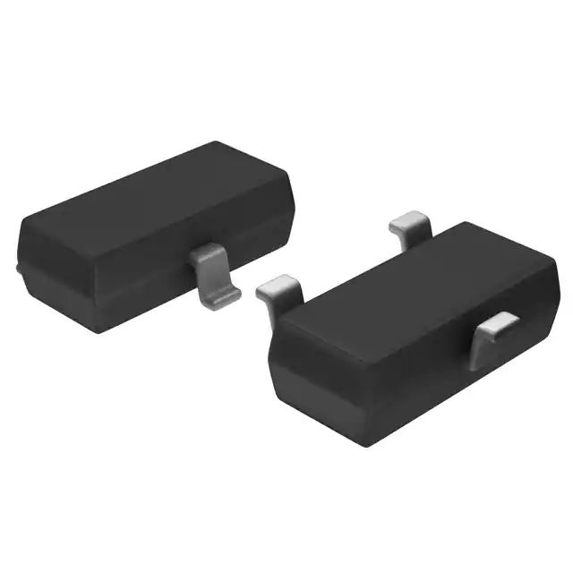
  • ZPY75-TR
  • ZPY75-TR PDF
  • ZPY75-TR Datasheet
  • ZPY75-TR Specifications
  • ZPY75-TR Images
  • Vishay General Semiconductor - Diodes Division
  • Vishay General Semiconductor - Diodes Division ZPY75-TR
  • Buy ZPY75-TR
  • ZPY75-TR Price
  • ZPY75-TR Distributor
  • ZPY75-TR Supplier
  • ZPY75-TR Wholesale
Related Products
MMBZ5240B-7-F
MMBZ5240B-7-F

Diodes Incorporated

BZT52C5V6T-7
BZT52C5V6T-7

Diodes Incorporated

MMSZ5231B-7-F
MMSZ5231B-7-F

Diodes Incorporated

BZT52C15-7-F
BZT52C15-7-F

Diodes Incorporated

BZX84C3V3LT1G
BZX84C3V3LT1G

onsemi

MMSZ5245BS-7-F
MMSZ5245BS-7-F

Diodes Incorporated

MMSZ4682T1G
MMSZ4682T1G

onsemi

BZT52C15S-7-F
BZT52C15S-7-F

Diodes Incorporated

MM5Z5V1ST1G
MM5Z5V1ST1G

onsemi

SMAJ4744A-TP
SMAJ4744A-TP

Micro Commercial Co

BZT52C3V6LP-7
BZT52C3V6LP-7

Diodes Incorporated

SMAZ12-13-F
SMAZ12-13-F

Diodes Incorporated

Tech Hub

Search

Search

PRODUCT

PRODUCT

PHONE

PHONE

USER

USER