
 My Inquiry
 My Account


Skyworks Solutions Inc. 513BAA000644BAGR
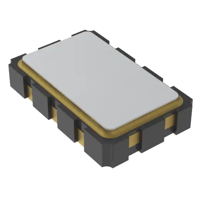
- Part No.:
- 513BAA000644BAGR
- Manufacturer:
- Skyworks Solutions Inc.
- Category:
- Pin Configurable/Selectable Oscillators
- Package:
- 6-SMD, No Lead
- Datasheet:
-
 513BAA000644BAGR.pdf
- Description:
- XTAL OSC XO 3.3V 6SMD
- Quantity:
- Payment:

- Shipping:

Inventory:7,708
Please send an inquiry. Send us your inquiry, and we will respond immediately.
Product details
Overview
513BAA000644BAGR from Skyworks Solutions is a dual-frequency crystal oscillator (XO) with factory-programmed frequencies of 100 MHz and 125 MHz, operating at 3.3 V with ±30 ppm total stability over –40 to +85 °C. It uses DSPLL® synthesis on a fixed crystal, supports LVPECL/LVDS/HCSL/CMOS outputs, and delivers low jitter (1.3 ps RMS period jitter for LVPECL). It serves as a precision clock source in PCIe Gen3/Gen4 root complexes and FPGA-based telecom line cards.
For engineers reviewing the 513BAA000644BAGR datasheet, 513BAA000644BAGR pinout, 513BAA000644BAGR application, or 513BAA000644BAGR equivalent, key selection criteria include dual-frequency switching via FS pin, OE polarity configuration, supply noise rejection performance, and compatibility with 3.2×5 mm 6-pin surface-mount footprint.
Technical Context
The 513BAA000644BAGR implements Skyworks' DSPLL® architecture with a fixed internal crystal and fractional-N synthesizer, enabling any-frequency generation from 100 kHz to 250 MHz without external crystals. Its dual-output capability is realized through a single PLL core with frequency-select logic routed to CLK+/CLK– or CMOS CLK pins depending on output format.
It integrates an on-chip LDO regulator for supply noise filtering, supports runt suppression on OE and power-on reset, and includes internal pull-up/pull-down resistors (45 kΩ) on FS and OE pins. The device is factory-configured - no field programming - with frequencies, voltage, output format, and stability permanently programmed before shipment.
Key Specifications
| Parameter | Value and Actual Design Meaning |
|---|---|
| Nominal Frequencies | 100 MHz and 125 MHz - factory-programmed dual outputs selectable via FS pin; enables dynamic clock domain switching without external multiplexers. |
| Output Format | LVPECL/LVDS/HCSL/CMOS - supports high-speed serial interfaces including PCIe, SATA, and Fibre Channel with signal integrity-optimized drive strength. |
| Total Stability | ±30 ppm - includes initial accuracy, temperature variation (–40 to +85 °C), supply/load changes, shock/vibration, and 10-year aging at 40 °C. |
| Supply Voltage | 3.3 V ±10% - compatible with standard logic rails; internal LDO ensures stable core operation despite board-level supply ripple. |
| Period Jitter (RMS) | 1.3 ps (LVPECL) - meets PCIe Gen3/Gen4 reference clock jitter requirements (<1.5 ps RMS) for reliable high-speed link training. |
| Startup Time | ≤10 ms - time from minimum VDD to output within frequency tolerance; enables fast system boot and hot-plug readiness. |
| Package | 3.2 × 5.0 mm, 6-pin SMD - industry-standard footprint compatible with automated placement and reflow per JEDEC J-STD-020E. |
Pinout & Package
513BAA000644BAGR is supplied in a 3.2 × 5.0 mm, 6-pin surface-mount package (package code B). Pin 1 = OE, Pin 2 = FS, Pin 3 = GND, Pin 4 = CLK+, Pin 5 = CLK–, Pin 6 = VDD.
| Pin/Terminal | Circuit Role | Design Meaning |
|---|---|---|
| 1 (OE) | Output Enable | Active-high control input with internal 45 kΩ pull-up; disables both outputs when low, reducing system power during idle states. |
| 2 (FS) | Frequency Select | Digital select input (0 = 100 MHz, 1 = 125 MHz); supports real-time clock domain switching without interrupting system operation. |
| 3 (GND) | Ground Reference | Common electrical and case ground; must be connected to low-impedance PCB ground plane to minimize jitter and EMI. |
| 4 (CLK+) | Differential Clock Output | Non-inverted LVPECL/LVDS/HCSL output; requires 50 Ω termination to VDD – 2 V (LVPECL) or 100 Ω differential (LVDS). |
| 5 (CLK–) | Differential Clock Output | Inverted complement of CLK+; used with CLK+ to deliver low-skew, noise-rejecting differential signaling. |
| 6 (VDD) | Power Supply | 3.3 V ±10% input; powers internal LDO, PLL, and output drivers; bypass capacitor (0.1 µF) required adjacent to pin. |
Key Features
| Feature | Design Value |
|---|---|
| Dual-frequency DSPLL® synthesis | Enables two precise, factory-set frequencies (100/125 MHz) from one device - eliminates need for dual discrete XOs and reduces BOM count and board area. |
| On-chip LDO regulator | Provides >30 dB supply noise rejection up to 1 MHz, allowing direct connection to noisy system rails without external filtering components. |
| Runt suppression on OE and power-on | Prevents false clock edges during enable transitions or brown-out conditions - critical for deterministic FPGA configuration and SerDes lock acquisition. |
| Factory-programmed configuration | Delivers fully functional, tested device with zero NRE or lead time for custom frequencies - accelerates design-in and production ramp. |
| Industry-standard 3.2×5 mm package | Ensures drop-in compatibility with existing layout footprints and pick-and-place tooling across telecom, computing, and industrial platforms. |
Applications
| PCIe Gen3/Gen4 Root Complex | FPGA-Based Telecom Line Card |
|---|---|
Use Scenario: Providing reference clocks to multiple PCIe endpoints and switch upstream/downstream ports in server backplanes. IC Role / Device Role / Timing Role: Dual-frequency XO supplying synchronized 100 MHz (for management subsystem) and 125 MHz (for data path) clocks with sub-ps jitter. Use Value: Eliminates clock tree complexity and skew between domains while meeting PCIe Gen4 jitter spec (1.5 ps RMS) for reliable link training at 16 GT/s. | Use Scenario: Clocking multi-gigabit SerDes transceivers (e.g., CPRI, eCPRI, OTN) and packet processing ASICs in 5G baseband units. IC Role / Device Role / Timing Role: Primary timing source delivering low-jitter 125 MHz for data-path synchronization and 100 MHz for control-plane timing. Use Value: Enables deterministic latency and phase alignment across distributed FPGAs and DSPs, supporting strict 5G fronthaul timing budgets (±1.5 µs). |
| SATA/SAS Storage Controller | Broadcast Video Timing Generator |
Use Scenario: Driving SATA Gen3 (6 Gbps) and SAS-3 (12 Gbps) host bus adapters requiring separate reference clocks for PHY and link layer. IC Role / Device Role / Timing Role: Dual-output XO providing 100 MHz for controller logic and 125 MHz for SerDes PHY, both with <2 ps pk-pk jitter. Use Value: Reduces bit error rate (BER) in high-speed storage interconnects by maintaining tight eye opening and minimizing deterministic jitter accumulation. | Use Scenario: Generating SMPTE ST 2082 (12G-SDI) and ST 2081 (6G-SDI) reference clocks in broadcast cameras and routing switchers. IC Role / Device Role / Timing Role: Precision clock source delivering 125 MHz (for 12G-SDI pixel clock) and 100 MHz (for auxiliary timing and genlock) with ±30 ppm stability over temperature. Use Value: Ensures frame-accurate synchronization across multi-camera systems and prevents video artifacts caused by clock drift or jitter-induced timing errors. |
Equivalent & Alternatives
The following parts are listed as comparable options for similar dual-frequency oscillator applications.
| Alternative Part | Technical Difference | Application Difference | Selection Advice |
|---|---|---|---|
| Si512BAA000644BAGR | OE pin on Pin 2 (vs. Pin 1 on 513BAA000644BAGR); identical frequencies, stability, and package. | Requires PCB layout revision to swap OE/FS pin assignments; not pin-compatible. | Select only if redesigning board layout to match Si512's OE-on-Pin-2 convention. |
| Si542A-A02579-GM | Single-output, 125 MHz only; ultra-low jitter (0.17 ps RMS); 2.5 V supply; 2.0 × 2.5 mm package. | Lacks dual-frequency capability and FS control; smaller footprint but no frequency switching. | Choose when only one frequency is needed and jitter budget is tighter than 513BAA000644BAGR's 1.3 ps RMS. |
Compared with Si512BAA000644BAGR, 513BAA000644BAGR offers native OE-on-Pin-1 layout compatibility for new designs, while Si542A-A02579-GM trades dual-frequency flexibility for superior jitter performance and space savings where single-frequency operation suffices.
Availability
513BAA000644BAGR is available at Aetrix Electronics and suitable for PCIe Gen4 root complexes, FPGA-based telecom line cards, and SATA/SAS storage controllers requiring stable component supply with guaranteed long-term availability and full traceability.
Supply support for 513BAA000644BAGR includes scheduled delivery planning, volume procurement assistance, BOM continuity management, traceable sourcing, and lifecycle availability coordination for OEM customers, industrial embedded developers, connected-device designers, and electronics production programs.
Manufacturer
Skyworks Solutions is a global semiconductor company specializing in analog and mixed-signal connectivity solutions, with leadership in RF, timing, and power management ICs.
The Si512/513 family is designed for high-reliability, programmable clock generation in datacenter, telecom, and enterprise infrastructure - prioritizing low jitter, dual-frequency agility, and rapid customization without NRE.
FAQ
What are the factory-programmed frequencies of the 513BAA000644BAGR?
The 513BAA000644BAGR is factory-programmed with two precise output frequencies: 100 MHz and 125 MHz. These values are permanently stored in non-volatile memory and cannot be altered in the field. Frequency selection is controlled by the logic level applied to the FS pin (Pin 2): FS = 0 selects 100 MHz, FS = 1 selects 125 MHz. Both frequencies are delivered simultaneously on complementary differential outputs (CLK+/CLK–) when enabled.
Is the 513BAA000644BAGR pin-compatible with other Si512/513 variants?
No - the 513BAA000644BAGR has OE on Pin 1 and FS on Pin 2, which differs from Si512-series devices (OE on Pin 2, FS on Pin 1). While both share the same 3.2×5 mm 6-pin package outline and pin numbering, swapping them requires PCB layout modification. The 513BAA000644BAGR is pin-compatible only with other Si513-part-numbered devices sharing the same package code (B) and output format configuration.
What output formats does the 513BAA000644BAGR support?
The 513BAA000644BAGR supports LVPECL, LVDS, HCSL, and CMOS output formats - selected at factory configuration. As indicated by its part number suffix "BAA", this unit is configured for LVPECL/LVDS/HCSL/Dual CMOS operation (not CMOS-only), meaning it delivers differential outputs on Pins 4 (CLK+) and 5 (CLK–). CMOS-only variants use different pinouts (CLK on Pin 4, NC on Pin 5) and are designated with "C" or "K" in the output format code.
Does the 513BAA000644BAGR require external configuration or programming after soldering?
No - the 513BAA000644BAGR is fully factory-programmed prior to shipment. All parameters - including frequencies (100/125 MHz), output format (LVPECL/LVDS/HCSL), supply voltage (3.3 V), total stability (±30 ppm), OE polarity, and FS functionality - are permanently written into the device. No I²C, SPI, or other interface is present; operation begins immediately upon power-up with no initialization sequence required.
How does the on-chip LDO in the 513BAA000644BAGR improve system-level jitter performance?
The integrated LDO regulator in the 513BAA000644BAGR provides >30 dB supply noise rejection up to 1 MHz, effectively isolating the sensitive PLL core from board-level power rail noise. This allows the 513BAA000644BAGR to maintain 1.3 ps RMS period jitter even when powered directly from a noisy 3.3 V system rail - eliminating the need for external LDOs, ferrite beads, or complex decoupling networks typically required for discrete oscillators.
513BAA000644BAGR Specifications
- Product attributes
- Attribute value
- Manufacturer:
- Skyworks Solutions Inc.
- Series:
- Si513
- Package/Case:
- 6-SMD, No Lead
- Packaging:
- Tape & Reel (TR)
- Product Status:
- Active
- Base Resonator:
- Crystal
- Type:
- XO (Standard)
- Frequency - Output 1:
- 161.1328MHz, 174.7031MHz
- Frequency - Output 2:
- -
- Frequency - Output 3:
- -
- Frequency - Output 4:
- -
- Function:
- Enable/Disable
- Output:
- LVDS
- Voltage - Supply:
- 3.3V
- Frequency Stability:
- ±50ppm
- Operating Temperature:
- -40°C ~ 85°C
- Current - Supply (Max):
- 23mA
- Ratings:
- -
- Size / Dimension:
- 0.197" L x 0.126" W (5.00mm x 3.20mm)
- Height:
- 0.052" (1.33mm)
- Supplier Device Package:
- -
513BAA000644BAGR FAQ
1.How can I place an order for 513BAA000644BAGR through Aetrix?
Please submit a Request for Quotation (RFQ) for 513BAA000644BAGR on Aetrix. Our sales agent will provide a competitive quotation and guide you through the order confirmation once you accept the terms.
2.Are the price and stock information for 513BAA000644BAGR reliable?
The price and inventory of 513BAA000644BAGR are updated periodically and may fluctuate due to market conditions. Stock and pricing data are typically refreshed every 24 hours. Quotation validity for 513BAA000644BAGR is usually 5 days.
3.What payment methods are accepted for 513BAA000644BAGR?
We accept Wire Transfer, PayPal, Credit Card, Western Union, MoneyGram, and Escrow for 513BAA000644BAGR transactions.
Note: Certain payment methods may incur a processing fee.
4.How is shipping managed for 513BAA000644BAGR?
513BAA000644BAGR orders can be shipped via leading logistics carriers, including DHL, UPS, FedEx, TNT, or Registered Mail.
Once your 513BAA000644BAGR order is processed, you will receive an email with the shipment details and tracking number.
Note: Tracking information may take up to 24 hours to appear. Express delivery typically takes 3–5 business days.
5.How can I obtain technical support or documentation for 513BAA000644BAGR?
For technical support, including 513BAA000644BAGR datasheets, pinout diagrams, or application guidance, please contact our engineering support team. They can provide detailed documentation and assistance for your 513BAA000644BAGR requirements.
6.How does Aetrix verify that 513BAA000644BAGR is sourced from the original manufacturer or authorized distributors?
All 513BAA000644BAGR products on Aetrix are procured from qualified distributors and authorized channels. Our dedicated quality assurance team conducts strict verification, including traceability checks and, if necessary, third-party testing. This ensures that 513BAA000644BAGR meets industry standards.
7.What is the process for return or replacement of 513BAA000644BAGR?
All 513BAA000644BAGR units undergo pre-shipment inspection (PSI). If there is an issue with 513BAA000644BAGR, returns or replacements are accepted under the following conditions:
1.Quantity discrepancies, incorrect items, or visible external defects (such as breakage or corrosion), acknowledged by Aetrix.
2.The issue is reported within 90 days of delivery.
3.The 513BAA000644BAGR part is unused and in its original packaging.
Return procedure for 513BAA000644BAGR:
1.Submit a request within 90 days.
2.Obtain a Return Material Authorization (RMA) from Aetrix.
513BAA000644BAGR Tags

-
ASEMDHC-L-R
Abracon LLC
-
513FCA000270AAG
Skyworks Solutions Inc.
-
LMK61PD0A2-SIAT
Texas Instruments
-
ASEMDLV-LR
Abracon LLC
2x1,6x0,9.JPG)
-
AMPDAFI-A09T
Abracon LLC
3,2x2,5x0,9.JPG)
-
AMPDEFH-A04T
Abracon LLC
-
534DC000596DG
Skyworks Solutions Inc.
-
ASEMCLV
Abracon LLC
-
DSC6021CI2A-009TT
Microchip Technology
-
DSC6021CI2A-009UT
Microchip Technology
-
DSC6021CI2A-009WT
Microchip Technology
-
DSC6021CI2A-009YT
Microchip Technology
Tech Hub

Counterfeit components can hide behind convincing markings and passing basic function tests. This engineering reference covers source traceability, external inspection, X-ray, XRF, electrical testing, …

A practical engineering and sourcing framework covering lifecycle verification, lifetime-buy calculations, replacement qualification, supplier checks and counterfeit-risk controls.

TTL and CMOS logic families differ in thresholds, loading, output drive, power and timing. This engineering guide compares 74HC and 74HCT, calculates noise margins and checks 3.3 V/5 V compatibility.

A practical engineering guide to 3.3V and 5V logic compatibility, input thresholds, resistor dividers, translator ICs, MOSFET level shifting, I2C pull-ups, timing limits and power-sequencing risks.

The 74HC595 uses push-pull logic outputs, while the TPIC6B595 uses 50 V open-drain DMOS sinks for higher-power loads. This guide compares timing, current limits, 3.3 V interfacing, load wiring, thermal…

The 74HC595 converts serial data into eight stable parallel outputs. This guide covers pin functions, shift and storage timing, OE and MR behavior, drive-current limits, cascading, voltage compatibilit…

A technical comparison of level-sensitive latches and edge-triggered flip-flops, covering timing windows, setup and hold limits, master–slave operation, time borrowing, race-through, HDL inference and…

A D latch stores one bit while Enable controls when data can pass. This reference covers gate-level operation, truth tables, transparency, setup and hold timing, LE versus OE, common ICs and practical …

An SR latch stores one bit through cross-coupled feedback. This engineering reference covers NOR and NAND implementations, truth tables, forbidden-state recovery, gated operation, switch debouncing, fa…

Latch circuits retain one bit through feedback. This technical reference covers SR and D latches, truth tables, transparency, timing limits, latch-versus-flip-flop behavior, applications and common log…


