
 My Inquiry
 My Account


Skyworks Solutions Inc. 532CA000174DGR
- Part No.:
- 532CA000174DGR
- Manufacturer:
- Skyworks Solutions Inc.
- Category:
- Pin Configurable/Selectable Oscillators
- Package:
- 6-SMD, No Lead
- Datasheet:
-
 532CA000174DGR.pdf
- Description:
- XTAL OSC XO 3.3V 6SMD
- Quantity:
- Payment:

- Shipping:

Inventory:5,001
Please send an inquiry. Send us your inquiry, and we will respond immediately.
Product details
Overview
532CA000174DGR from Skyworks Solutions is a dual-frequency, factory-programmed crystal oscillator (XO) with DSPLL® synthesis, delivering two selectable output frequencies in the 10–945 MHz range (CMOS-compatible up to 160 MHz), ±7 ppm temperature stability, 3.3 V supply, and LVPECL output format. It serves as a low-jitter timing source in FPGA clocking, SD/HD video systems, and test equipment where frequency agility and supply noise rejection are critical.
For engineers reviewing the 532CA000174DGR datasheet, 532CA000174DGR pinout, 532CA000174DGR application, or 532CA000174DGR equivalent, this device offers verified dual-frequency switching via FS pin, tristate control via OE, industry-standard 5 × 7 mm SMT package, and RMS phase jitter as low as 0.25 ps (12 kHz–20 MHz, >500 MHz outputs).
Technical Context
The 532CA000174DGR implements Skyworks' third-generation DSPLL® architecture, using a fixed internal crystal reference to synthesize two user-specified frequencies without external components. Its PLL-based synthesis enables high-frequency operation while maintaining ±7 ppm total stability over –40 to +85 °C ambient.
It supports CMOS output mode (up to 160 MHz), with 3.3 V supply, active-high OE and FS control pins featuring integrated 17 kΩ pullups to VDD. Output enable places CLK+/CLK– into high-impedance state; frequency select toggles between preprogrammed f₀ and f₁ within the 10–945 MHz band.
Key Specifications
| Parameter | Value and Actual Design Meaning |
|---|---|
| Nominal Frequency | Two factory-set frequencies in 10–945 MHz range; CMOS limited to ≤160 MHz |
| Temperature Stability | ±7 ppm over –40 to +85 °C - ensures minimal drift in industrial environments |
| Phase Jitter (RMS) | 0.25 ps typical (12 kHz–20 MHz, >500 MHz outputs) - meets OC-48 telecom timing requirements |
| Supply Voltage | 3.3 V ±10% - compatible with standard logic rails and simplifies power design |
| Output Format | LVPECL - provides differential signaling with 1.1–1.9 VPP swing for noise immunity |
| Package | 5 × 7 mm, 6-pin surface-mount - matches industry-standard footprint for drop-in layout reuse |
| Aging (20-year) | ±10 ppm - guarantees long-term frequency accuracy without recalibration |
Pinout & Package
532CA000174DGR uses an industry-standard 6-pin, 5 × 7 mm surface-mount ceramic package with exposed pad (not electrically connected). Pin 1 is marked by a dot; orientation follows top-view numbering (1–6 clockwise from top-left).
| Pin/Terminal | Circuit Role | Design Meaning |
|---|---|---|
| 1 (FS) | Frequency Select Input | Logic-level control: FS = 0 selects first frequency; FS = 1 selects second; internal 17 kΩ pullup to VDD |
| 2 (OE) | Output Enable Input | Active-high enable: OE = 0 forces CLK+/CLK– into high-impedance state; internal 17 kΩ pullup to VDD |
| 3 (GND) | Ground Reference | Common return path for power and signal; connects to PCB ground plane for noise suppression |
| 4 (CLK+) | Differential Clock Output | LVPECL positive output; requires 50 Ω termination to VDD – 2.0 V for proper level compliance |
| 5 (CLK–) | Differential Clock Output | LVPECL complementary output; paired with CLK+ for balanced signaling and jitter reduction |
| 6 (VDD) | Power Supply Input | 3.3 V supply input; decoupling capacitor (0.1 µF) required near pin for supply noise rejection |
Key Features
| Feature | Design Value |
|---|---|
| Dual-frequency selection | Two factory-programmed frequencies switched in <10 ms via FS pin - eliminates need for multiple oscillators |
| DSPLL® jitter performance | 0.25 ps RMS phase jitter (12 kHz–20 MHz) - enables clean sampling in high-speed ADCs and SerDes |
| Fixed internal crystal | Eliminates crystal aging variability and enables ±7 ppm stability - improves long-term system timing margin |
| Supply noise rejection | Superior PSRR from DSPLL architecture - maintains low jitter even with noisy 3.3 V rail (e.g., FPGA power domains) |
| Industry-standard footprint | 5 × 7 mm, 6-pad layout - allows direct replacement of legacy XOs without PCB redesign |
Applications
| SD/HD Video Timing | FPGA Clock Generation |
|---|---|
Use Scenario: Synchronizing pixel clocks and frame timing in broadcast-grade video encoders and HDMI transmitters. IC Role / Device Role / Timing Role: Primary reference clock source for video PHYs and pixel clock synthesizers. Use Value: Dual-frequency capability supports both 74.25 MHz (HD) and 148.5 MHz (3G-SDI) modes with sub-0.3 ps jitter - prevents video artifacts and frame sync loss. |
Use Scenario: Providing configurable, low-jitter clocks to multiple FPGA I/O banks and transceivers. IC Role / Device Role / Timing Role: System-level clock generator enabling multi-domain clocking (e.g., PCIe, DDR, logic fabric). Use Value: FS-selectable frequencies allow dynamic reconfiguration of FPGA clock trees without external switches or PLL reprogramming. |
| Test & Measurement Equipment | Clock and Data Recovery (CDR) |
Use Scenario: Serving as stable timebase in digital oscilloscopes and arbitrary waveform generators. IC Role / Device Role / Timing Role: Precision reference for ADC sampling clocks and DAC update timing. Use Value: ±7 ppm stability and <0.3 ps jitter ensure measurement repeatability across temperature and long-duration acquisitions. |
Use Scenario: Generating clean reference clocks for CDR circuits in optical line cards and Ethernet PHYs. IC Role / Device Role / Timing Role: Low-phase-noise clock source for PLL-based data retiming. Use Value: Phase noise floor of –144 dBc/Hz at 1 MHz offset (622.08 MHz LVPECL) minimizes bit error rate in 10G/25G serial links. |
Equivalent & Alternatives
The following parts are listed as comparable options for similar dual-frequency XO applications.
| Alternative Part | Technical Difference | Application Difference | Selection Advice |
|---|---|---|---|
| Si5332A-D-GM | Programmable 4-output clock generator with integrated jitter cleaners; wider frequency range (0.16–3.2 GHz); requires configuration via I²C | Used in complex multi-clock systems requiring jitter attenuation and fanout; not pin-compatible | Select when needing >2 outputs, programmability, or sub-100 fs jitter - adds firmware overhead and BOM cost |
| MAX2671EUT+T | Single-output 10–1000 MHz XO with ±20 ppm stability; no frequency select pin; CMOS/LVDS only; 3.3 V only | Suitable for fixed-frequency applications where dual-mode operation is unnecessary | Choose for cost-sensitive, single-frequency designs where ±20 ppm stability suffices and FS/OE control is unused |
Compared with 532CA000174DGR, Si5332A-D-GM offers greater flexibility but demands configuration infrastructure, while MAX2671EUT+T reduces cost and complexity at the expense of dual-frequency capability and tighter stability - making 532CA000174DGR optimal for deterministic, field-reconfigurable timing in space-constrained industrial systems.
Availability
532CA000174DGR is available at Aetrix Electronics and suitable for SD/HD video timing, FPGA clock generation, and test & measurement equipment requiring stable component supply, consistent lead times, and full traceability.
Supply support for 532CA000174DGR includes scheduled delivery planning, volume procurement assistance, BOM continuity management, traceable sourcing, and lifecycle availability coordination for OEM customers, industrial embedded developers, connected-device designers, and electronics production programs.
Manufacturer
Skyworks Solutions is a global semiconductor company specializing in analog and mixed-signal connectivity solutions, with leadership in RF, timing, and precision analog products.
The Si532 family is designed specifically for high-performance, dual-frequency clock generation in communication infrastructure, video systems, and instrumentation - emphasizing jitter performance, configurability, and reliability without external tuning components.
FAQ
What output frequencies are programmed in the 532CA000174DGR?
The 532CA000174DGR is factory-programmed with two specific frequencies determined by its six-digit code "000174". Per Skyworks' part numbering convention, codes >000100 indicate the lower frequency is selected when FS = 0 and the higher when FS = 1. Exact values are defined at order time and documented in the device's configuration record. The 532CA000174DGR operates within the 10–945 MHz band, with CMOS output limited to ≤160 MHz.
Does the 532CA000174DGR support LVDS or CML output formats?
No, the 532CA000174DGR does not support LVDS or CML. Its part number suffix "C" indicates CMOS output format, and "A" denotes 3.3 V supply. While the Si532 family supports LVPECL, LVDS, CML, and CMOS, each variant is fixed at shipment. The 532CA000174DGR is configured exclusively for CMOS output - confirmed by its ordering code and electrical specs in Table 3 (CMOS VOH/VOL, rise/fall time, and load condition CL = 15 pF).
What is the power-up time and frequency switching time for the 532CA000174DGR?
The 532CA000174DGR has a maximum power-up time (tOSC) of 10 ms - the interval from VDD stabilization to valid CLK+ and CLK– output. Frequency switching via the FS pin completes within 10 ms (tFRQ), as specified in Table 2. These timings are independent of output format and apply across all supply voltages and temperature ranges (–40 to +85 °C).
How is temperature stability defined for the 532CA000174DGR?
The 532CA000174DGR has ±7 ppm temperature stability, meaning its output frequency deviation due to ambient temperature variation (–40 to +85 °C) does not exceed ±7 ppm from nominal. This value excludes initial calibration error (±1.5 ppm) and aging (±3 ppm first year), resulting in a total stability of ±20 ppm - a key differentiator versus SAW-based oscillators.
Can the 532CA000174DGR be used with a 2.5 V or 1.8 V supply?
No, the 532CA000174DGR is configured for 3.3 V operation only. Its part number prefix "532C" specifies CMOS output, and the "A" in position 4 of the ordering code explicitly denotes 3.3 V supply (per Figure 1's Option Code table). Using 2.5 V or 1.8 V would violate Absolute Maximum Ratings and result in undefined behavior or failure to meet output voltage specifications.
532CA000174DGR Specifications
- Product attributes
- Attribute value
- Manufacturer:
- Skyworks Solutions Inc.
- Series:
- Si532
- Package/Case:
- 6-SMD, No Lead
- Packaging:
- Tape & Reel (TR)
- Product Status:
- Active
- Base Resonator:
- Crystal
- Type:
- XO (Standard)
- Frequency - Output 1:
- 45.1584MHz, 49.152MHz
- Frequency - Output 2:
- -
- Frequency - Output 3:
- -
- Frequency - Output 4:
- -
- Function:
- Enable/Disable
- Output:
- CMOS
- Voltage - Supply:
- 3.3V
- Frequency Stability:
- ±50ppm
- Operating Temperature:
- -40°C ~ 85°C
- Current - Supply (Max):
- 88mA
- Ratings:
- -
- Size / Dimension:
- 0.276" L x 0.197" W (7.00mm x 5.00mm)
- Height:
- 0.071" (1.80mm)
- Supplier Device Package:
- -
532CA000174DGR FAQ
1.How can I place an order for 532CA000174DGR through Aetrix?
Please submit a Request for Quotation (RFQ) for 532CA000174DGR on Aetrix. Our sales agent will provide a competitive quotation and guide you through the order confirmation once you accept the terms.
2.Are the price and stock information for 532CA000174DGR reliable?
The price and inventory of 532CA000174DGR are updated periodically and may fluctuate due to market conditions. Stock and pricing data are typically refreshed every 24 hours. Quotation validity for 532CA000174DGR is usually 5 days.
3.What payment methods are accepted for 532CA000174DGR?
We accept Wire Transfer, PayPal, Credit Card, Western Union, MoneyGram, and Escrow for 532CA000174DGR transactions.
Note: Certain payment methods may incur a processing fee.
4.How is shipping managed for 532CA000174DGR?
532CA000174DGR orders can be shipped via leading logistics carriers, including DHL, UPS, FedEx, TNT, or Registered Mail.
Once your 532CA000174DGR order is processed, you will receive an email with the shipment details and tracking number.
Note: Tracking information may take up to 24 hours to appear. Express delivery typically takes 3–5 business days.
5.How can I obtain technical support or documentation for 532CA000174DGR?
For technical support, including 532CA000174DGR datasheets, pinout diagrams, or application guidance, please contact our engineering support team. They can provide detailed documentation and assistance for your 532CA000174DGR requirements.
6.How does Aetrix verify that 532CA000174DGR is sourced from the original manufacturer or authorized distributors?
All 532CA000174DGR products on Aetrix are procured from qualified distributors and authorized channels. Our dedicated quality assurance team conducts strict verification, including traceability checks and, if necessary, third-party testing. This ensures that 532CA000174DGR meets industry standards.
7.What is the process for return or replacement of 532CA000174DGR?
All 532CA000174DGR units undergo pre-shipment inspection (PSI). If there is an issue with 532CA000174DGR, returns or replacements are accepted under the following conditions:
1.Quantity discrepancies, incorrect items, or visible external defects (such as breakage or corrosion), acknowledged by Aetrix.
2.The issue is reported within 90 days of delivery.
3.The 532CA000174DGR part is unused and in its original packaging.
Return procedure for 532CA000174DGR:
1.Submit a request within 90 days.
2.Obtain a Return Material Authorization (RMA) from Aetrix.
532CA000174DGR Tags

-
ASEMDHC-L-R
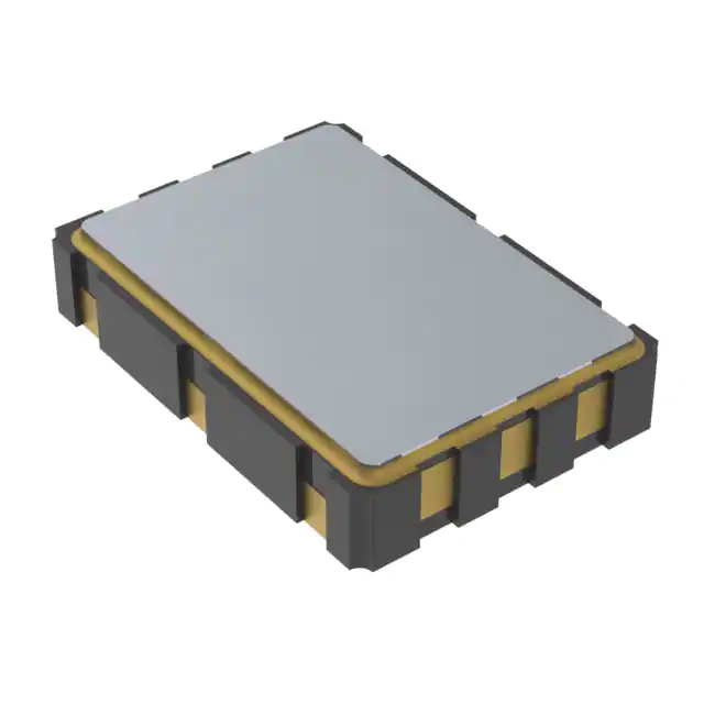
Abracon LLC
-
513FCA000270AAG
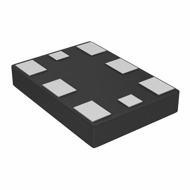
Skyworks Solutions Inc.
-
LMK61PD0A2-SIAT
Texas Instruments
-
ASEMDLV-LR
Abracon LLC
2x1,6x0,9.JPG)
-
AMPDAFI-A09T
Abracon LLC
3,2x2,5x0,9.JPG)
-
AMPDEFH-A04T
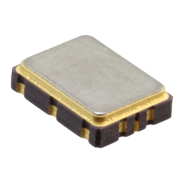
Abracon LLC
-
534DC000596DG
Skyworks Solutions Inc.
-
ASEMCLV
Abracon LLC
-
DSC6021CI2A-009TT
Microchip Technology
-
DSC6021CI2A-009UT
Microchip Technology
-
DSC6021CI2A-009WT
Microchip Technology
-
DSC6021CI2A-009YT
Microchip Technology
Tech Hub

Counterfeit components can hide behind convincing markings and passing basic function tests. This engineering reference covers source traceability, external inspection, X-ray, XRF, electrical testing, …

A practical engineering and sourcing framework covering lifecycle verification, lifetime-buy calculations, replacement qualification, supplier checks and counterfeit-risk controls.

TTL and CMOS logic families differ in thresholds, loading, output drive, power and timing. This engineering guide compares 74HC and 74HCT, calculates noise margins and checks 3.3 V/5 V compatibility.

A practical engineering guide to 3.3V and 5V logic compatibility, input thresholds, resistor dividers, translator ICs, MOSFET level shifting, I2C pull-ups, timing limits and power-sequencing risks.

The 74HC595 uses push-pull logic outputs, while the TPIC6B595 uses 50 V open-drain DMOS sinks for higher-power loads. This guide compares timing, current limits, 3.3 V interfacing, load wiring, thermal…

The 74HC595 converts serial data into eight stable parallel outputs. This guide covers pin functions, shift and storage timing, OE and MR behavior, drive-current limits, cascading, voltage compatibilit…

A technical comparison of level-sensitive latches and edge-triggered flip-flops, covering timing windows, setup and hold limits, master–slave operation, time borrowing, race-through, HDL inference and…

A D latch stores one bit while Enable controls when data can pass. This reference covers gate-level operation, truth tables, transparency, setup and hold timing, LE versus OE, common ICs and practical …

An SR latch stores one bit through cross-coupled feedback. This engineering reference covers NOR and NAND implementations, truth tables, forbidden-state recovery, gated operation, switch debouncing, fa…

Latch circuits retain one bit through feedback. This technical reference covers SR and D latches, truth tables, transparency, timing limits, latch-versus-flip-flop behavior, applications and common log…


