
 My Inquiry
 My Account


Skyworks Solutions Inc. 542CAA002475BCG
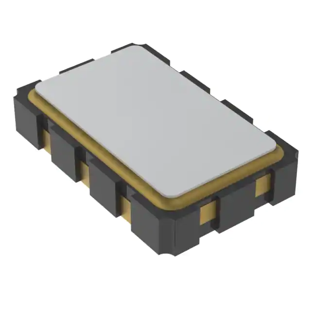
- Part No.:
- 542CAA002475BCG
- Manufacturer:
- Skyworks Solutions Inc.
- Category:
- Pin Configurable/Selectable Oscillators
- Package:
- 8-SMD, No Lead
- Datasheet:
-
 542CAA002475BCG.pdf
- Description:
- OSCILLATOR SMD
- Quantity:
- Payment:

- Shipping:

Inventory:3,153
Please send an inquiry. Send us your inquiry, and we will respond immediately.
Product details
Overview
542CAA002475BCG from Skyworks Solutions is an ultra-low-jitter quad-output crystal oscillator (XO) based on 4th-generation DSPLL® technology, delivering four factory-programmed frequencies between 0.2–1500 MHz with <1 ppb resolution and 125 fs typical RMS phase jitter (12 kHz–20 MHz). It supports LVPECL/LVDS/CML/HCSL/CMOS/Dual CMOS outputs, operates from 1.8/2.5/3.3 V, and is packaged in a 5×7 mm CLCC. It serves as a timing source for high-speed serial interfaces requiring deterministic clocking.
For engineers reviewing the 542CAA002475BCG datasheet, 542CAA002475BCG pinout, 542CAA002475BCG application, or 542CAA002475BCG equivalent, this page provides verified technical context, pin-level circuit roles, real-world use cases in coherent optics and FPGA clocking, and validated alternative options for multi-frequency timing systems.
Technical Context
The 542CAA002475BCG implements a digital fractional-N DSPLL architecture with integrated DCO, digital phase detector, and loop filter - enabling simultaneous synthesis of four independent output frequencies without external crystals. Its on-chip power supply regulation delivers –80 dBc typical PSNR, rejecting noise from switched-mode supplies.
Frequency selection is controlled via two logic inputs (FS0, FS1), each with internal 50 kΩ pull-up to VDD; output enable (OE) polarity and pin location are factory-configured. The device guarantees 100% electrical testing and supports 7 ppm temperature stability (–40 to +85 °C) with ±20 ppm total stability including aging.
Key Specifications
| Parameter | Value and Actual Design Meaning |
|---|---|
| Output Frequencies | Four user-defined frequencies from 0.2 to 1500 MHz, selectable via FS[1:0] pins - enables single-device replacement of multiple XOs in multi-clock-domain systems. |
| Phase Jitter (RMS) | 125 fs typical (12 kHz–20 MHz) for differential outputs - meets stringent jitter budgets for 100G/400G Ethernet and OTN clock recovery. |
| Supply Voltage Range | 1.8 V, 2.5 V, or 3.3 V ±5% - same part number supports mixed-voltage board designs without redesign. |
| Output Formats | LVPECL, LVDS, CML, HCSL, CMOS, or Dual CMOS - eliminates need for external level-shifting or buffering in FPGA/ASIC clock trees. |
| Temperature Stability | ±7 ppm over –40 to +85 °C - ensures frequency accuracy across industrial operating conditions without oven control. |
| Package | 5×7 mm 8-pin CLCC - industry-standard footprint compatible with automated SMT assembly and thermal management per ΘJA = 53 °C/W. |
| Total Stability | ±20 ppm (includes temp, initial accuracy, load pulling, VDD variation, and 20-year aging at 70 °C) - simplifies long-term system timing margin analysis. |
Pinout & Package
542CAA002475BCG is housed in a 5×7 mm 8-pin ceramic leadless chip carrier (CLCC) package with gull-wing–style terminations and gold-plated contact pads (Au/Ni). The package meets MIL-STD-883 mechanical reliability standards and has MSL Level 1 moisture sensitivity.
| Pin/Terminal | Circuit Role | Design Meaning |
|---|---|---|
| 1, 2 | OE / NC | Selectable output enable pin (active-high or active-low); unused pin configured as no-connect - allows flexible signal routing and board layout reuse. |
| 3 | GND | Dedicated ground terminal - provides low-impedance return path for all internal circuits and output drivers to minimize ground bounce. |
| 4 | CLK+ | Differential clock output positive leg - delivers full-swing LVPECL/LVDS/CML or single-ended CMOS depending on configuration. |
| 5 | CLK− | Differential clock output negative leg - unused in CMOS mode; required for noise-immune differential signaling in high-speed SerDes links. |
| 6 | VDD | Single power supply input (1.8/2.5/3.3 V) - powers all internal PLL, memory, and output stages; includes on-chip filtering for >80 dB PSNR. |
| 7 | FS1 | Frequency select bit 1 - binary-encoded control input (with FS0) to choose one of four preprogrammed output frequencies. |
| 8 | FS0 | Frequency select bit 0 - used with FS1 to configure output frequency selection (00 to 11); internally pulled up to VDD. |
Key Features
| Feature | Design Value |
|---|---|
| Quad Any-Frequency Synthesis | Four independently programmable frequencies (0.2–1500 MHz) with <1 ppb resolution - replaces discrete oscillators and reduces BOM count in multi-rate systems. |
| Ultra-Low Phase Jitter | 125 fs RMS (12 kHz–20 MHz) in 5×7 mm package - enables compliance with IEEE 802.3bs 400G KR8 and OIF CEI-56G-LR jitter masks. |
| Multi-Voltage & Multi-Format Output | Single part supports 1.8/2.5/3.3 V operation and six output formats - eliminates voltage translation ICs and simplifies clock tree design. |
| Factory-Configurable OE & Pinout | OE polarity (active-high/low) and pin assignment (Pin 1 or Pin 2) set at shipment - avoids post-manufacture hardware modifications. |
| On-Chip Power Supply Filtering | –80 dBc typical PSNR - maintains jitter performance in noisy environments with SMPS, reducing need for external LDOs or ferrites. |
| 1–2 Week Custom Sample Lead Time | Full electrical test and programming performed before shipment - accelerates prototyping versus traditional crystal-based XOs. |
Applications
| 100G/400G Coherent Optics | High-Speed FPGA Clocking |
|---|---|
Use Scenario: Timing reference for DP-QPSK modulator/demodulator ASICs and ADC/DAC sampling clocks in CFP2/CFP4 coherent transceivers. IC Role / Device Role / Timing Role: Primary low-jitter clock source for analog front-end sampling and digital signal processing blocks. Use Value: 125 fs jitter ensures <0.5 UI eye opening degradation at 64 GBd, meeting OIF Implementation Agreement IA#3.3 requirements. |
Use Scenario: Providing four synchronized clocks to different FPGA regions (e.g., PCIe Gen5 interface, DDR5 memory controller, DSP core, and Ethernet MAC). IC Role / Device Role / Timing Role: Quad-output timing engine eliminating inter-clock skew and reducing PCB trace length vs. discrete oscillators. Use Value: Single 5×7 mm device replaces four separate XOs, cutting board area by >60% and improving thermal uniformity across clock domains. |
| 10G/25G/100G Ethernet Switches | Broadcast Video (12G-SDI/24G-SDI) |
Use Scenario: Reference clock for SERDES lanes in enterprise switches and data center top-of-rack routers supporting IEEE 802.3bj/ck. IC Role / Device Role / Timing Role: Low-phase-noise clock generator for PMA/PMD layers with guaranteed jitter performance across temperature and voltage. Use Value: ±7 ppm stability and –160 dBc/Hz phase noise at 10 MHz offset ensure BER <1e–12 under worst-case channel loss and crosstalk. |
Use Scenario: Master timing source for SMPTE ST 2082-1 (24G-SDI) video encoders/decoders and frame synchronizers in broadcast production gear. IC Role / Device Role / Timing Role: Ultra-stable quad-frequency oscillator generating pixel clock, line sync, field sync, and audio sample clocks. Use Value: Four precisely aligned outputs eliminate inter-frame timing drift and support seamless switching between 4K/8K video formats. |
Equivalent & Alternatives
The following parts are listed as comparable options for similar quad-frequency oscillator applications.
| Alternative Part | Technical Difference | Application Difference | Selection Advice |
|---|---|---|---|
| Si544BA002475BCG | Same Si54x family, but supports only two output frequencies (dual-output) and uses 3.2×5 mm package - lower pin count, reduced thermal mass. | Limited to dual-frequency systems; not suitable where four independent clocks are required. | Choose when board space is constrained and only two frequencies are needed - saves ~30% footprint vs. 5×7 mm. |
| LMK5B33414RGZT | Texas Instruments' 4-output jitter cleaner with integrated PLL; higher power (190 mA typ), larger 7×7 mm QFN, and requires external loop filter components. | Designed for jitter attenuation rather than pure frequency synthesis; better for cleaning noisy references than generating clean clocks from crystal. | Prefer when input reference is degraded (e.g., from backplane traces) and sub-100 fs residual jitter is required after cleanup. |
Compared with Si544BA002475BCG, the 542CAA002475BCG delivers two additional programmable outputs in a thermally robust 5×7 mm package, while the LMK5B33414RGZT adds jitter cleaning capability at the cost of higher complexity and power - making the 542CAA002475BCG optimal for direct, low-power, multi-frequency generation.
Availability
542CAA002475BCG is available at Aetrix Electronics and suitable for 100G/400G optical modules, high-speed FPGA platforms, Ethernet switch silicon validation, and broadcast video equipment requiring stable component supply and rapid custom-frequency fulfillment.
Supply support for 542CAA002475BCG includes scheduled delivery planning, volume procurement assistance, BOM continuity management, traceable sourcing, and lifecycle availability coordination for OEM customers, industrial embedded developers, connected-device designers, and electronics production programs.
Manufacturer
Skyworks Solutions is a global semiconductor company specializing in analog and mixed-signal connectivity solutions, with leadership in RF, timing, and power management technologies.
The Si542 series belongs to Skyworks' Ultra Series™ timing portfolio, engineered specifically for high-speed serial data applications demanding ultra-low jitter, multi-frequency flexibility, and rapid customization without crystal inventory constraints.
FAQ
What output formats does the 542CAA002475BCG support?
The 542CAA002475BCG supports LVPECL, LVDS, CML, HCSL, CMOS, and Dual CMOS output formats. The specific format is factory-programmed at time of shipment and cannot be changed in-circuit. Each format has defined voltage swing, common-mode levels, and termination requirements documented in the Si542 datasheet - for example, LVDS outputs deliver 0.7 VPP swing into 100 Ω differential load, while CMOS supports 3.3/2.5/1.8 V logic levels with rail-to-rail swing.
How are the four output frequencies selected on the 542CAA002475BCG?
The 542CAA002475BCG uses two dedicated frequency select pins (FS0 and FS1) to choose among its four factory-programmed frequencies. These pins accept standard CMOS logic levels (VIH ≥ 0.7×VDD, VIL ≤ 0.3×VDD) and each includes an internal 50 kΩ pull-up resistor to VDD. Valid combinations are FS[1:0] = 00, 01, 10, and 11 - each mapping to one of the four preconfigured frequencies specified during ordering.
What is the total frequency stability specification for the 542CAA002475BCG?
The 542CAA002475BCG has a total stability of ±20 ppm, which includes contributions from temperature variation (±7 ppm over –40 to +85 °C), initial calibration accuracy, load pulling, supply voltage variation, and 20-year aging at 70 °C. This value is guaranteed across the full operating range and is used for worst-case timing budget analysis in synchronous systems such as OTN framers and SerDes PHYs.
Does the 542CAA002475BCG require external configuration or programming after soldering?
No, the 542CAA002475BCG is fully factory-programmed before shipment - all parameters including the four output frequencies, output format, OE polarity, OE pin location, and voltage supply option are permanently stored in on-chip NVM. No external I²C/SPI interface or configuration sequence is needed; the device begins operating within 10 ms of VDD reaching 0.9× rated voltage.
What package type and thermal characteristics apply to the 542CAA002475BCG?
The 542CAA002475BCG uses a 5×7 mm 8-pin ceramic leadless chip carrier (CLCC) package with Au/Ni contact pads and MSL Level 1 rating. Its thermal resistance junction-to-ambient (ΘJA) is 53 °C/W under still air conditions, and junction-to-board (ΨJB) is 26 °C/W - enabling reliable operation up to +85 °C ambient with standard 4-layer PCB copper pours beneath the exposed pad area.
542CAA002475BCG Specifications
- Product attributes
- Attribute value
- Manufacturer:
- Skyworks Solutions Inc.
- Series:
- Ultra™ Si542
- Package/Case:
- 8-SMD, No Lead
- Packaging:
- Strip
- Product Status:
- Active
- Base Resonator:
- Crystal
- Type:
- XO (Standard)
- Frequency - Output 1:
- 10MHz, 60MHz
- Frequency - Output 2:
- -
- Frequency - Output 3:
- -
- Frequency - Output 4:
- -
- Function:
- Enable/Disable
- Output:
- CMOS
- Voltage - Supply:
- 1.8V ~ 3.3V
- Frequency Stability:
- ±20ppm
- Operating Temperature:
- -40°C ~ 85°C
- Current - Supply (Max):
- 108mA
- Ratings:
- -
- Size / Dimension:
- 0.197" L x 0.126" W (5.00mm x 3.20mm)
- Height:
- 0.052" (1.33mm)
- Supplier Device Package:
- -
542CAA002475BCG FAQ
1.How can I place an order for 542CAA002475BCG through Aetrix?
Please submit a Request for Quotation (RFQ) for 542CAA002475BCG on Aetrix. Our sales agent will provide a competitive quotation and guide you through the order confirmation once you accept the terms.
2.Are the price and stock information for 542CAA002475BCG reliable?
The price and inventory of 542CAA002475BCG are updated periodically and may fluctuate due to market conditions. Stock and pricing data are typically refreshed every 24 hours. Quotation validity for 542CAA002475BCG is usually 5 days.
3.What payment methods are accepted for 542CAA002475BCG?
We accept Wire Transfer, PayPal, Credit Card, Western Union, MoneyGram, and Escrow for 542CAA002475BCG transactions.
Note: Certain payment methods may incur a processing fee.
4.How is shipping managed for 542CAA002475BCG?
542CAA002475BCG orders can be shipped via leading logistics carriers, including DHL, UPS, FedEx, TNT, or Registered Mail.
Once your 542CAA002475BCG order is processed, you will receive an email with the shipment details and tracking number.
Note: Tracking information may take up to 24 hours to appear. Express delivery typically takes 3–5 business days.
5.How can I obtain technical support or documentation for 542CAA002475BCG?
For technical support, including 542CAA002475BCG datasheets, pinout diagrams, or application guidance, please contact our engineering support team. They can provide detailed documentation and assistance for your 542CAA002475BCG requirements.
6.How does Aetrix verify that 542CAA002475BCG is sourced from the original manufacturer or authorized distributors?
All 542CAA002475BCG products on Aetrix are procured from qualified distributors and authorized channels. Our dedicated quality assurance team conducts strict verification, including traceability checks and, if necessary, third-party testing. This ensures that 542CAA002475BCG meets industry standards.
7.What is the process for return or replacement of 542CAA002475BCG?
All 542CAA002475BCG units undergo pre-shipment inspection (PSI). If there is an issue with 542CAA002475BCG, returns or replacements are accepted under the following conditions:
1.Quantity discrepancies, incorrect items, or visible external defects (such as breakage or corrosion), acknowledged by Aetrix.
2.The issue is reported within 90 days of delivery.
3.The 542CAA002475BCG part is unused and in its original packaging.
Return procedure for 542CAA002475BCG:
1.Submit a request within 90 days.
2.Obtain a Return Material Authorization (RMA) from Aetrix.
542CAA002475BCG Tags

-
ASEMDHC-L-R
Abracon LLC
-
513FCA000270AAG
Skyworks Solutions Inc.
-
LMK61PD0A2-SIAT
Texas Instruments
-
ASEMDLV-LR
Abracon LLC
2x1,6x0,9.JPG)
-
AMPDAFI-A09T
Abracon LLC
3,2x2,5x0,9.JPG)
-
AMPDEFH-A04T
Abracon LLC
-
534DC000596DG
Skyworks Solutions Inc.
-
ASEMCLV
Abracon LLC
-
DSC6021CI2A-009TT
Microchip Technology
-
DSC6021CI2A-009UT
Microchip Technology
-
DSC6021CI2A-009WT
Microchip Technology
-
DSC6021CI2A-009YT
Microchip Technology
Tech Hub

Counterfeit components can hide behind convincing markings and passing basic function tests. This engineering reference covers source traceability, external inspection, X-ray, XRF, electrical testing, …

A practical engineering and sourcing framework covering lifecycle verification, lifetime-buy calculations, replacement qualification, supplier checks and counterfeit-risk controls.

TTL and CMOS logic families differ in thresholds, loading, output drive, power and timing. This engineering guide compares 74HC and 74HCT, calculates noise margins and checks 3.3 V/5 V compatibility.

A practical engineering guide to 3.3V and 5V logic compatibility, input thresholds, resistor dividers, translator ICs, MOSFET level shifting, I2C pull-ups, timing limits and power-sequencing risks.

The 74HC595 uses push-pull logic outputs, while the TPIC6B595 uses 50 V open-drain DMOS sinks for higher-power loads. This guide compares timing, current limits, 3.3 V interfacing, load wiring, thermal…

The 74HC595 converts serial data into eight stable parallel outputs. This guide covers pin functions, shift and storage timing, OE and MR behavior, drive-current limits, cascading, voltage compatibilit…

A technical comparison of level-sensitive latches and edge-triggered flip-flops, covering timing windows, setup and hold limits, master–slave operation, time borrowing, race-through, HDL inference and…

A D latch stores one bit while Enable controls when data can pass. This reference covers gate-level operation, truth tables, transparency, setup and hold timing, LE versus OE, common ICs and practical …

An SR latch stores one bit through cross-coupled feedback. This engineering reference covers NOR and NAND implementations, truth tables, forbidden-state recovery, gated operation, switch debouncing, fa…

Latch circuits retain one bit through feedback. This technical reference covers SR and D latches, truth tables, transparency, timing limits, latch-versus-flip-flop behavior, applications and common log…


