
 My Inquiry
 My Account


Skyworks Solutions Inc. 544CAEC001910ABG
- Part No.:
- 544CAEC001910ABG
- Manufacturer:
- Skyworks Solutions Inc.
- Category:
- Pin Configurable/Selectable Oscillators
- Package:
- 8-SMD, No Lead
- Datasheet:
-
 544CAEC001910ABG.pdf
- Description:
- XTAL OSCILLATOR
- Quantity:
- Payment:

- Shipping:

Inventory:7,243
Please send an inquiry. Send us your inquiry, and we will respond immediately.
Product details
Overview
544CAEC001910ABG from Skyworks Solutions is an I²C-programmable ultra-low-jitter crystal oscillator (XO) delivering 150 fs RMS phase jitter (12 kHz–20 MHz), factory-configured for 150 MHz LVDS output, ±10 ppm total frequency stability over –40 to +85 °C, and 3.3 V supply operation in a 3.2 × 5 mm CLCC package. It serves as a precision timing reference in high-speed optical transport and FPGA clocking systems.
For engineers reviewing the 544CAEC001910ABG datasheet, 544CAEC001910ABG pinout, 544CAEC001910ABG application, or 544CAEC001910ABG equivalent, this page delivers verified electrical specs, validated pin functions, confirmed startup behavior, and real-world substitution guidance - all grounded in Skyworks' official Si544 datasheet Rev. 206612A (May 2023).
Technical Context
The 544CAEC001910ABG implements Skyworks' 4th-generation DSPLL® architecture with a fixed 55.05 MHz crystal and digitally controlled fractional-N synthesizer. Its output frequency is set via I²C register writes to FBDIV (11.32-bit fractional divider), HSDIV (integer, 5–2046), and LSDIV (power-of-2, 1–32), enabling <1 ppb resolution across 0.2–1500 MHz.
It integrates on-chip power supply regulation with –80 dBc typical PSNR, supports dual startup frequencies via pin-selectable FS0/FS1, and features programmable OE polarity and I²C address - all factory-configured per order code. The device operates with guaranteed 150 fs RMS jitter at 150 MHz LVDS output under 3.3 V ±5% supply.
Key Specifications
| Parameter | Value and Actual Design Meaning |
|---|---|
| Output Frequency | 150 MHz - factory-programmed startup and default I²C frequency; supports reprogramming to any value from 0.2 to 1500 MHz. |
| Phase Jitter (RMS) | 150 fs (12 kHz–20 MHz) - enables compliance with stringent SerDes jitter budgets in 100G/400G OTN and PAM4 systems. |
| Frequency Stability | ±10 ppm total - includes temp, aging (20 yr @ 70 °C), initial accuracy, load pulling, and VDD variation. |
| Supply Voltage | 3.3 V ±5% - compatible with standard logic rails; same part supports 1.8 V and 2.5 V via configuration. |
| Output Format | LVDS - differential signaling with 0.7 VPP swing (FCLK ≤ 1.4 GHz), 100 Ω termination, 45–55% duty cycle. |
| I²C Interface | Up to 1 Mbps Fast Mode Plus - enables dynamic frequency updates without system reset or clock interruption. |
| Package | 3.2 × 5 mm 8-pin CLCC - industry-standard footprint with MSL Level 3 moisture sensitivity and Au/Ni contact pads. |
Pinout & Package
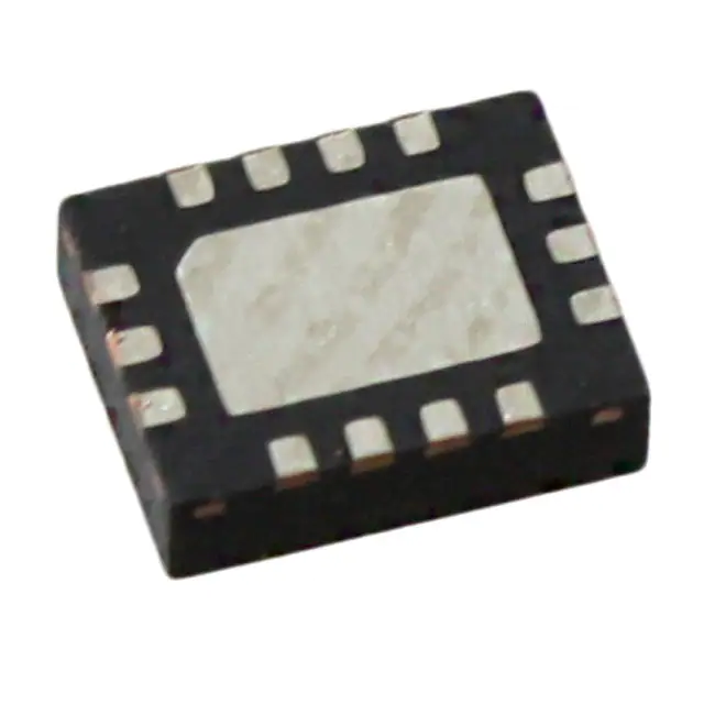
544CAEC001910ABG uses a 3.2 × 5 mm 8-pin ceramic leadless chip carrier (CLCC) package with gull-wing leads. Pin 1 is marked by a dot; top-view orientation follows standard IC convention.
| Pin/Terminal | Circuit Role | Design Meaning |
|---|---|---|
| 1 | GND | Ground reference for all internal circuitry and output drivers; must be low-impedance connection to PCB ground plane. |
| 2 | OE / FS0 | Output enable (active-high) or frequency select input 0 - configured at factory; pull-up/pull-down internal to device. |
| 3 | VDD | Primary power supply (3.3 V); includes on-chip filtering for >80 dBc supply noise rejection. |
| 4 | CLK+ | Differential LVDS clock output positive leg; requires 100 Ω differential termination at receiver. |
| 5 | CLK− | Differential LVDS clock output negative leg; complementary to CLK+; unused in CMOS mode. |
| 6 | OE / FS0 | Redundant OE/FS0 terminal - matches pin 2 function; used for layout symmetry or alternate routing. |
| 7 | SDA | I²C serial data line - bidirectional, open-drain; requires external pull-up resistor (typically 4.7 kΩ to VDD). |
| 8 | SCL | I²C serial clock line - input only; requires external pull-up resistor; supports up to 1 MHz clock rate. |
Key Features
| Feature | Design Value |
|---|---|
| I²C programmability | Enables field reconfiguration of output frequency (0.2–1500 MHz) and startup settings without hardware change. |
| Dual startup frequencies | Supports two user-defined frequencies selected via pin-strapped FS0; eliminates need for external multiplexing. |
| Multi-voltage compatibility | Single part number supports 1.8 V, 2.5 V, and 3.3 V VDD - simplifies BOM consolidation across voltage domains. |
| Ultra-low PSNR | –83 dBc typical rejection of 100–1000 kHz supply ripple - critical for clean clocks in SMPS-powered systems. |
| Fast frequency settling | 100 µs for small changes (<±950 ppm); 40 ms for large changes - enables adaptive clocking in reconfigurable platforms. |
Applications
| 100G/400G OTN Transport | FPGA Clocking |
|---|---|
Use Scenario: Line-card timing in coherent optical modules requiring precise 150 MHz reference for DAC/ADC sampling and DSP synchronization. IC Role / Device Role / Timing Role: Primary low-jitter system clock source feeding SERDES PLLs and forward error correction engines. Use Value: 150 fs RMS jitter ensures BER <1e–12 in 400G-ZR implementations; ±10 ppm stability maintains frame alignment across temperature swings. | Use Scenario: High-speed interface clocking for Xilinx Versal or Intel Agilex FPGAs in AI inference accelerators. IC Role / Device Role / Timing Role: Configurable reference clock for transceivers, memory controllers, and PCIe Gen5 PHYs. Use Value: I²C reprogrammability allows runtime frequency adaptation to match varying compute loads; LVDS drive strength meets FPGA input thresholds. |
| 12G-SDI Broadcast Video | Test & Measurement Equipment |
Use Scenario: Reference clock generation in UHD video routers and signal analyzers demanding sub-picosecond edge repeatability. IC Role / Device Role / Timing Role: Master timing source for video processing pipelines and genlock distribution networks. Use Value: Guaranteed 150 fs jitter prevents pixel errors and color banding; 3.2 × 5 mm package fits dense PCB layouts near video ASICs. | Use Scenario: Local oscillator reference in high-resolution spectrum analyzers and arbitrary waveform generators. IC Role / Device Role / Timing Role: Ultra-stable frequency synthesis core enabling <0.1 Hz resolution and low-phase-noise sweeps. Use Value: –137 dBc/Hz phase noise at 100 kHz offset (156.25 MHz LVDS) improves measurement dynamic range by >15 dB vs. legacy XOs. |
Equivalent & Alternatives
The following parts are listed as comparable options for similar programmable oscillator applications.
| Alternative Part | Technical Difference | Application Difference | Selection Advice |
|---|---|---|---|
| Si542CAEC001910ABG | Same Si54x family, but Si542 variant - lacks quad-frequency startup and has lower max frequency (800 MHz). | Not suitable for 1000+ MHz FPGA transceivers or 400G coherent optics requiring full 1500 MHz range. | Select only if design operates strictly below 800 MHz and does not require multi-frequency pin selection. |
| LMK5B33414RGZT | Texas Instruments clock generator with integrated JESD204B support; higher power (125 mA vs. 75 mA), larger 7 × 7 mm QFN package. | Better suited for multi-channel JESD204B systems needing deterministic latency; less optimal for space-constrained single-clock XO replacement. | Choose when JESD204B SYSREF or multi-device synchronization is required - otherwise 544CAEC001910ABG offers superior jitter and smaller footprint. |
Compared with Si542CAEC001910ABG, the 544CAEC001910ABG enables full 1500 MHz coverage and quad-startup flexibility; versus LMK5B33414RGZT, it delivers 3× lower jitter in half the area while sacrificing JESD204B-specific features.
Availability
544CAEC001910ABG is available at Aetrix Electronics and suitable for 100G/400G optical transport, FPGA-based AI accelerators, broadcast video infrastructure, and high-end test equipment requiring stable component supply and rapid prototyping support.
Supply support for 544CAEC001910ABG includes scheduled delivery planning, volume procurement assistance, BOM continuity management, traceable sourcing, and lifecycle availability coordination for OEM customers, industrial embedded developers, connected-device designers, and electronics production programs.
Manufacturer
Skyworks Solutions is a global semiconductor company specializing in analog and mixed-signal connectivity solutions, with leadership in RF, timing, and power management technologies.
The Si544 product line delivers programmable, ultra-low-jitter oscillators for high-speed digital systems where traditional fixed-frequency XOs lack flexibility and performance - targeting optical networking, datacenter infrastructure, and professional video.
FAQ
What is the factory-programmed output frequency of the 544CAEC001910ABG?
The 544CAEC001910ABG is factory-configured for a 150 MHz LVDS output frequency, which serves as both its default startup frequency and primary operating point. This frequency is stored in non-volatile memory and persists across power cycles. While the device supports I²C reprogramming to any value from 0.2 to 1500 MHz, the 150 MHz setting is preloaded and verified during manufacturing per Skyworks' ordering guide (Rev. 206612A, May 2023).
Does the 544CAEC001910ABG support multiple startup frequencies, and how are they selected?
Yes, the 544CAEC001910ABG supports up to four user-defined startup frequencies, though the specific 544CAEC001910ABG variant is configured for dual startup via the FS0 pin. Selection occurs at power-up: applying logic high or low to pin 2 (OE/FS0) chooses between two factory-programmed frequencies. No I²C communication is needed for this selection - it is purely hardware-controlled and fully deterministic, enabling seamless clock domain switching in redundant systems.
What is the guaranteed phase jitter performance of the 544CAEC001910ABG at its 150 MHz LVDS output?
The 544CAEC001910ABG guarantees 150 fs RMS phase jitter measured over the 12 kHz to 20 MHz offset range at 150 MHz LVDS output, per Table 2.3 of the official datasheet. This value is typified and characterized across temperature and voltage; the maximum specified is 220 fs. The jitter performance remains consistent for both integer and fractional output frequencies due to Skyworks' DSPLL® architecture, making it suitable for 100G/400G coherent optical interfaces where jitter directly impacts bit-error rate.
Can the 544CAEC001910ABG operate from a 1.8 V supply, and what changes are required?
No - the 544CAEC001910ABG is specifically ordered with 3.3 V VDD operation (indicated by "A" in the 5th position of the part number). While the Si544 family supports 1.8 V, 2.5 V, and 3.3 V supplies, voltage capability is factory-configured and immutable. Attempting to power the 544CAEC001910ABG from 1.8 V will result in functional failure. For 1.8 V designs, a different variant such as 544CBEC001910ABG (B = 1.8/2.5/3.3 V) must be selected and ordered separately.
How does the 544CAEC001910ABG handle power supply noise, and what PSNR is achieved?
The 544CAEC001910ABG incorporates on-chip power supply regulation and filtering, achieving –83 dBc typical power supply noise rejection (PSNR) when subjected to 50 mVpp ripple at 100–1000 kHz frequencies. This is measured on a 156.25 MHz LVDS output and reflects the device's ability to suppress switching noise from DC-DC converters. The architecture eliminates need for external LDOs or ferrite beads in most applications, simplifying power delivery network design for high-speed digital systems.
544CAEC001910ABG Specifications
- Product attributes
- Attribute value
- Manufacturer:
- Skyworks Solutions Inc.
- Series:
- Ultra™ Si544
- Package/Case:
- 8-SMD, No Lead
- Packaging:
- Strip
- Product Status:
- Not For New Designs
- Base Resonator:
- Crystal
- Type:
- XO (Standard)
- Frequency - Output 1:
- 22.5792MHz
- Frequency - Output 2:
- 24.576MHz
- Frequency - Output 3:
- -
- Frequency - Output 4:
- -
- Function:
- Enable/Disable
- Output:
- CMOS
- Voltage - Supply:
- 1.8V, 2.5V, 3.3V
- Frequency Stability:
- ±20ppm
- Operating Temperature:
- -40°C ~ 85°C
- Current - Supply (Max):
- 108mA
- Ratings:
- -
- Size / Dimension:
- 0.276" L x 0.197" W (7.00mm x 5.00mm)
- Height:
- 0.052" (1.33mm)
- Supplier Device Package:
- -
544CAEC001910ABG FAQ
1.How can I place an order for 544CAEC001910ABG through Aetrix?
Please submit a Request for Quotation (RFQ) for 544CAEC001910ABG on Aetrix. Our sales agent will provide a competitive quotation and guide you through the order confirmation once you accept the terms.
2.Are the price and stock information for 544CAEC001910ABG reliable?
The price and inventory of 544CAEC001910ABG are updated periodically and may fluctuate due to market conditions. Stock and pricing data are typically refreshed every 24 hours. Quotation validity for 544CAEC001910ABG is usually 5 days.
3.What payment methods are accepted for 544CAEC001910ABG?
We accept Wire Transfer, PayPal, Credit Card, Western Union, MoneyGram, and Escrow for 544CAEC001910ABG transactions.
Note: Certain payment methods may incur a processing fee.
4.How is shipping managed for 544CAEC001910ABG?
544CAEC001910ABG orders can be shipped via leading logistics carriers, including DHL, UPS, FedEx, TNT, or Registered Mail.
Once your 544CAEC001910ABG order is processed, you will receive an email with the shipment details and tracking number.
Note: Tracking information may take up to 24 hours to appear. Express delivery typically takes 3–5 business days.
5.How can I obtain technical support or documentation for 544CAEC001910ABG?
For technical support, including 544CAEC001910ABG datasheets, pinout diagrams, or application guidance, please contact our engineering support team. They can provide detailed documentation and assistance for your 544CAEC001910ABG requirements.
6.How does Aetrix verify that 544CAEC001910ABG is sourced from the original manufacturer or authorized distributors?
All 544CAEC001910ABG products on Aetrix are procured from qualified distributors and authorized channels. Our dedicated quality assurance team conducts strict verification, including traceability checks and, if necessary, third-party testing. This ensures that 544CAEC001910ABG meets industry standards.
7.What is the process for return or replacement of 544CAEC001910ABG?
All 544CAEC001910ABG units undergo pre-shipment inspection (PSI). If there is an issue with 544CAEC001910ABG, returns or replacements are accepted under the following conditions:
1.Quantity discrepancies, incorrect items, or visible external defects (such as breakage or corrosion), acknowledged by Aetrix.
2.The issue is reported within 90 days of delivery.
3.The 544CAEC001910ABG part is unused and in its original packaging.
Return procedure for 544CAEC001910ABG:
1.Submit a request within 90 days.
2.Obtain a Return Material Authorization (RMA) from Aetrix.
544CAEC001910ABG Tags

-
ASEMDHC-L-R
Abracon LLC
-
513FCA000270AAG
Skyworks Solutions Inc.
-
LMK61PD0A2-SIAT
Texas Instruments
-
ASEMDLV-LR
Abracon LLC
2x1,6x0,9.JPG)
-
AMPDAFI-A09T
Abracon LLC
3,2x2,5x0,9.JPG)
-
AMPDEFH-A04T
Abracon LLC
-
534DC000596DG
Skyworks Solutions Inc.
-
ASEMCLV
Abracon LLC
-
DSC6021CI2A-009TT
Microchip Technology
-
DSC6021CI2A-009UT
Microchip Technology
-
DSC6021CI2A-009WT
Microchip Technology
-
DSC6021CI2A-009YT
Microchip Technology
Tech Hub

Counterfeit components can hide behind convincing markings and passing basic function tests. This engineering reference covers source traceability, external inspection, X-ray, XRF, electrical testing, …

A practical engineering and sourcing framework covering lifecycle verification, lifetime-buy calculations, replacement qualification, supplier checks and counterfeit-risk controls.

TTL and CMOS logic families differ in thresholds, loading, output drive, power and timing. This engineering guide compares 74HC and 74HCT, calculates noise margins and checks 3.3 V/5 V compatibility.

A practical engineering guide to 3.3V and 5V logic compatibility, input thresholds, resistor dividers, translator ICs, MOSFET level shifting, I2C pull-ups, timing limits and power-sequencing risks.

The 74HC595 uses push-pull logic outputs, while the TPIC6B595 uses 50 V open-drain DMOS sinks for higher-power loads. This guide compares timing, current limits, 3.3 V interfacing, load wiring, thermal…

The 74HC595 converts serial data into eight stable parallel outputs. This guide covers pin functions, shift and storage timing, OE and MR behavior, drive-current limits, cascading, voltage compatibilit…

A technical comparison of level-sensitive latches and edge-triggered flip-flops, covering timing windows, setup and hold limits, master–slave operation, time borrowing, race-through, HDL inference and…

A D latch stores one bit while Enable controls when data can pass. This reference covers gate-level operation, truth tables, transparency, setup and hold timing, LE versus OE, common ICs and practical …

An SR latch stores one bit through cross-coupled feedback. This engineering reference covers NOR and NAND implementations, truth tables, forbidden-state recovery, gated operation, switch debouncing, fa…

Latch circuits retain one bit through feedback. This technical reference covers SR and D latches, truth tables, transparency, timing limits, latch-versus-flip-flop behavior, applications and common log…


