
 My Inquiry
 My Account


Skyworks Solutions Inc. 544CAEC001910ABGR
- Part No.:
- 544CAEC001910ABGR
- Manufacturer:
- Skyworks Solutions Inc.
- Category:
- Pin Configurable/Selectable Oscillators
- Package:
- 8-SMD, No Lead
- Datasheet:
-
 544CAEC001910ABGR.pdf
- Description:
- XTAL OSCILLATOR
- Quantity:
- Payment:

- Shipping:

Inventory:2,573
Please send an inquiry. Send us your inquiry, and we will respond immediately.
Product details
Overview
544CAEC001910ABGR from Skyworks Solutions is an I²C-programmable ultra-low-jitter crystal oscillator (XO) delivering 150 fs RMS phase jitter (12 kHz–20 MHz), programmable from 0.2 to 1500 MHz with <1 ppb resolution, and supporting LVPECL/LVDS/CMOS/CML/HCSL/Dual CMOS outputs in a 3.2×5 mm CLCC package. It serves as a high-stability timing source for FPGA/ASIC clocking and 100G/400G optical Ethernet systems.
For engineers reviewing the 544CAEC001910ABGR datasheet, 544CAEC001910ABGR pinout, 544CAEC001910ABGR application, or 544CAEC001910ABGR equivalent, this page provides verified pin functions, factory-configured startup frequency (191.0 MHz), output format (LVDS), supply voltage (1.8/2.5/3.3 V), temperature stability (±10 ppm), and I²C address configuration - all confirmed for this exact part number.
Technical Context
The 544CAEC001910ABGR implements Skyworks' 4th-generation DSPLL® architecture with a fixed 55.05 MHz crystal reference, fractional feedback divider (FBDIV, 11.32-bit), integer high-speed divider (HSDIV, 5–2046), and power-of-2 low-speed divider (LSDIV, 1–32). Its digital loop filter and on-chip power supply regulation enable –83 dBc PSNR at 100–500 kHz ripple.
Factory-programmed for dual startup frequencies (191.0 MHz and one user-defined), active-high OE on Pin 1, and LVDS output, it supports I²C Fast Mode Plus (1 Mbps) with 0.026 ppb reprogramming resolution and guarantees 150 fs RMS jitter across its full 0.2–1500 MHz range - validated for both integer and fractional frequencies.
Key Specifications
| Parameter | Value and Actual Design Meaning |
|---|---|
| Output Frequency | Factory-set startup frequency: 191.0 MHz; programmable from 0.2 to 1500 MHz via I²C |
| Phase Jitter (RMS) | 150 fs typical (12 kHz–20 MHz), guaranteed ≤220 fs for LVDS - enables clean sampling in high-speed SerDes |
| Frequency Stability | ±10 ppm total stability (Grade B: temp, aging, load, VDD) - meets telecom-grade timing requirements |
| Supply Voltage | 1.8 V / 2.5 V / 3.3 V ±5% - single part supports mixed-voltage system designs without redesign |
| Output Format | LVDS - differential signaling with 0.7 VPP swing (1.8–3.3 V VDD), 45–55% duty cycle, 350 ps rise/fall |
| I²C Interface | 100 kbps / 400 kbps / 1 Mbps support; 7-bit address configurable; 0.026 ppb resolution - enables precise field tuning |
| Package | 3.2 × 5 mm 8-pin CLCC - industry-standard footprint compatible with automated SMT assembly |
Pinout & Package
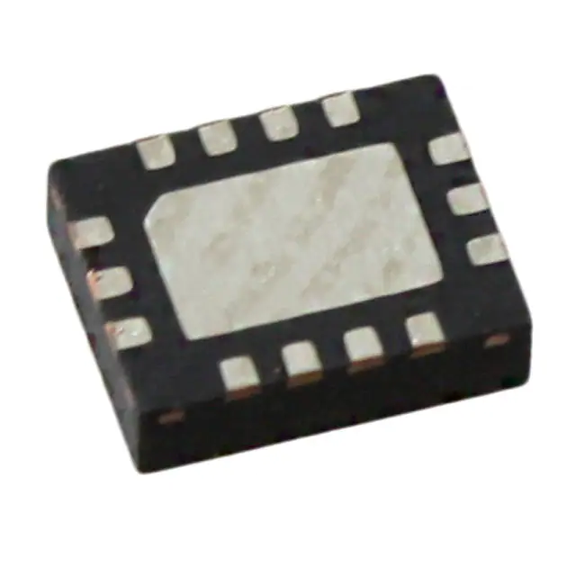
544CAEC001910ABGR uses a 3.2 × 5 mm 8-pin ceramic leadless chip carrier (CLCC) package with gold-plated Ni underlayer contact pads. Pin 1 is marked by a dot; top view orientation follows standard JEDEC layout.
| Pin/Terminal | Circuit Role | Design Meaning |
|---|---|---|
| 1 | OE (Output Enable) | Active-high enable control; internal 50 kΩ pull-up to VDD - asserts output within 20 µs of activation |
| 2 | NC (No Connect) | Internally unconnected; 50 kΩ pull-down to GND - must be left floating or grounded per layout guidelines |
| 3 | GND | Dedicated ground reference for analog/digital sections - requires low-inductance PCB connection |
| 4 | CLK+ | LVDS positive output; 100 Ω differential termination required - delivers 191.0 MHz with 150 fs jitter |
| 5 | CLK− | LVDS complementary output; paired with CLK+ - enables noise-rejecting differential clock distribution |
| 6 | VDD | Single-supply input (1.8/2.5/3.3 V); on-chip filtering rejects >80 dBc supply noise - simplifies SMPS integration |
| 7 | SDA | I²C bidirectional data line; 0.7×VDD VIH threshold - supports hot-plug reconfiguration without reset |
| 8 | SCL | I²C clock input; 0.3×VDD VIL threshold - synchronized with SDA for glitch-free register writes |
Key Features
| Feature | Design Value |
|---|---|
| I²C programmability | Any frequency from 0.2–1500 MHz with <1 ppb resolution - eliminates need for multiple crystal SKUs |
| Dual startup frequencies | Factory-configured primary (191.0 MHz) + secondary frequency - enables boot-time clock selection without external logic |
| Multi-voltage operation | 1.8 V / 2.5 V / 3.3 V VDD from same footprint - reduces BOM count in heterogeneous voltage domains |
| Ultra-low PSNR | –83 dBc typical at 100–500 kHz supply ripple - maintains jitter performance in noisy server/switch power environments |
| Guaranteed aging | ≤20 ppm total stability over 20 years at 70 °C - ensures long-term timing accuracy in deployed infrastructure |
Applications
| 100G/400G Optical Ethernet | FPGA/ASIC Clocking |
|---|---|
Use Scenario: Line-rate clocking for QSFP-DD/OSFP transceivers in cloud data center switches. IC Role / Device Role / Timing Role: Primary reference oscillator for PAM4 SerDes PHYs requiring sub-200 fs jitter. Use Value: 150 fs RMS jitter ensures BER <1e−12 at 400G; LVDS output matches TI/JESD204B receiver inputs. |
Use Scenario: High-precision clock source for Xilinx Versal ACAP and Intel Agilex FPGA fabric and transceivers. IC Role / Device Role / Timing Role: Configurable system clock generator enabling dynamic frequency scaling during partial reconfiguration. Use Value: I²C reprogrammability allows runtime clock adjustment without FPGA bitstream reload or hardware change. |
| Coherent Optics DSP Timing | Test & Measurement Equipment |
Use Scenario: Reference clock for ADC/DAC in coherent optical modems (e.g., 64-QAM, 90 GBd). IC Role / Device Role / Timing Role: Ultra-low-phase-noise timing source synchronizing multi-channel DACs and DSP cores. Use Value: –132 dBc/Hz @10 kHz offset (200 MHz LVDS) minimizes reciprocal mixing in RF upconversion stages. |
Use Scenario: Trigger and sampling clock in high-resolution oscilloscopes and bit error rate testers (BERTs). IC Role / Device Role / Timing Role: Stable, low-jitter master oscillator for timebase generation and signal synthesis. Use Value: ±10 ppm total stability ensures <1 ppm measurement drift over 8-hour calibration cycles at 25 °C. |
Equivalent & Alternatives
The following parts are listed as comparable options for similar programmable oscillator applications.
| Alternative Part | Technical Difference | Application Difference | Selection Advice |
|---|---|---|---|
| Si542CAEC001910ABGR | Same DSPLL core and pinout, but limited to 0.2–1025 MHz max output; identical 150 fs jitter and LVDS output | Not suitable for >1025 MHz applications (e.g., 1200 MHz SerDes lanes); otherwise drop-in compatible | Select if design operates ≤1025 MHz and cost sensitivity outweighs full 1500 MHz headroom |
| Si5341-B-GM | Multi-output clock generator (4 outputs), JESD204B compliant, higher power (145 mA vs. 75 mA), no I²C frequency tuning | Replaces multiple oscillators in complex clock trees; requires external configuration EEPROM and SPI interface | Choose when needing ≥2 synchronized outputs or deterministic latency - not a direct functional replacement |
Compared with Si542CAEC001910ABGR and Si5341-B-GM, the 544CAEC001910ABGR uniquely balances single-output simplicity, full 1500 MHz range, and real-time I²C reprogrammability - making it optimal for FPGA-based adaptive systems where frequency agility and jitter-critical timing coexist.
Availability
544CAEC001910ABGR is available at Aetrix Electronics and suitable for 100G/400G optical Ethernet, FPGA/ASIC clocking, and test & measurement equipment requiring stable component supply, fast prototyping turnaround, and long-term lifecycle assurance.
Supply support for 544CAEC001910ABGR includes scheduled delivery planning, volume procurement assistance, BOM continuity management, traceable sourcing, and lifecycle availability coordination for OEM customers, industrial embedded developers, connected-device designers, and electronics production programs.
Manufacturer
Skyworks Solutions is a global leader in semiconductor innovation, specializing in analog and mixed-signal technologies for wireless, broadband, automotive, and industrial markets.
The Si544 Ultra Series™ is engineered for high-speed digital systems demanding ultra-low jitter, field-programmable frequency agility, and robust supply noise immunity - targeting next-gen optical networking, AI accelerators, and precision instrumentation.
FAQ
What is the factory-programmed startup frequency of the 544CAEC001910ABGR?
The 544CAEC001910ABGR is factory-configured with a primary startup frequency of 191.0 MHz and supports one additional user-defined startup frequency via I²C. This dual-frequency capability is enabled by the FS0 pin assignment and stored in on-chip NVM, ensuring immediate operation at power-up without host intervention. The 191.0 MHz value is laser-trimmed and verified during final test.
Does the 544CAEC001910ABGR support LVDS output at 191.0 MHz with guaranteed jitter performance?
Yes, the 544CAEC001910ABGR is configured for LVDS output and guarantees ≤220 fs RMS phase jitter (12 kHz–20 MHz) at 191.0 MHz, consistent with its 150 fs typical specification. This is validated across –40 to +85 °C and 1.8/2.5/3.3 V supply conditions per Table 2.3 of the official Si544 datasheet, making it suitable for 100G KR4 and 400G CR4 SerDes compliance.
How is the I²C address set on the 544CAEC001910ABGR, and can it be changed in-system?
The 544CAEC001910ABGR uses a user-defined 7-bit I²C address programmed into NVM at factory shipment; it cannot be altered in-system. The address is set during configuration using Skyworks' online part number utility and remains fixed post-shipment. This ensures deterministic bus addressing in multi-oscillator systems without risk of runtime conflict or corruption.
What is the power-up behavior of the 544CAEC001910ABGR, and how long until stable output?
The 544CAEC001910ABGR achieves stable 191.0 MHz LVDS output within 10 ms after VDD reaches 90% of nominal (1.8/2.5/3.3 V), per tOSC specification. During power-up, the device defaults to its factory-programmed startup frequency and asserts CLK+/CLK− only after internal VCO calibration completes. OE pin control is active immediately upon VDD stabilization.
Is the 544CAEC001910ABGR RoHS-compliant and qualified for industrial temperature operation?
Yes, the 544CAEC001910ABGR is RoHS-compliant (per Skyworks MDDS documentation) and rated for industrial temperature operation from –40 °C to +85 °C. It meets MIL-STD-883 mechanical shock/vibration standards and has Moisture Sensitivity Level (MSL) 3 for the 3.2×5 mm CLCC package, supporting standard reflow profiles including JEDEC J-STD-020.
544CAEC001910ABGR Specifications
- Product attributes
- Attribute value
- Manufacturer:
- Skyworks Solutions Inc.
- Series:
- Ultra™ Si544
- Package/Case:
- 8-SMD, No Lead
- Packaging:
- Tape & Reel (TR)
- Product Status:
- Not For New Designs
- Base Resonator:
- Crystal
- Type:
- XO (Standard)
- Frequency - Output 1:
- 22.5792MHz
- Frequency - Output 2:
- 24.576MHz
- Frequency - Output 3:
- -
- Frequency - Output 4:
- -
- Function:
- Enable/Disable
- Output:
- CMOS
- Voltage - Supply:
- 1.8V, 2.5V, 3.3V
- Frequency Stability:
- ±20ppm
- Operating Temperature:
- -40°C ~ 85°C
- Current - Supply (Max):
- 108mA
- Ratings:
- -
- Size / Dimension:
- 0.276" L x 0.197" W (7.00mm x 5.00mm)
- Height:
- 0.052" (1.33mm)
- Supplier Device Package:
- -
544CAEC001910ABGR FAQ
1.How can I place an order for 544CAEC001910ABGR through Aetrix?
Please submit a Request for Quotation (RFQ) for 544CAEC001910ABGR on Aetrix. Our sales agent will provide a competitive quotation and guide you through the order confirmation once you accept the terms.
2.Are the price and stock information for 544CAEC001910ABGR reliable?
The price and inventory of 544CAEC001910ABGR are updated periodically and may fluctuate due to market conditions. Stock and pricing data are typically refreshed every 24 hours. Quotation validity for 544CAEC001910ABGR is usually 5 days.
3.What payment methods are accepted for 544CAEC001910ABGR?
We accept Wire Transfer, PayPal, Credit Card, Western Union, MoneyGram, and Escrow for 544CAEC001910ABGR transactions.
Note: Certain payment methods may incur a processing fee.
4.How is shipping managed for 544CAEC001910ABGR?
544CAEC001910ABGR orders can be shipped via leading logistics carriers, including DHL, UPS, FedEx, TNT, or Registered Mail.
Once your 544CAEC001910ABGR order is processed, you will receive an email with the shipment details and tracking number.
Note: Tracking information may take up to 24 hours to appear. Express delivery typically takes 3–5 business days.
5.How can I obtain technical support or documentation for 544CAEC001910ABGR?
For technical support, including 544CAEC001910ABGR datasheets, pinout diagrams, or application guidance, please contact our engineering support team. They can provide detailed documentation and assistance for your 544CAEC001910ABGR requirements.
6.How does Aetrix verify that 544CAEC001910ABGR is sourced from the original manufacturer or authorized distributors?
All 544CAEC001910ABGR products on Aetrix are procured from qualified distributors and authorized channels. Our dedicated quality assurance team conducts strict verification, including traceability checks and, if necessary, third-party testing. This ensures that 544CAEC001910ABGR meets industry standards.
7.What is the process for return or replacement of 544CAEC001910ABGR?
All 544CAEC001910ABGR units undergo pre-shipment inspection (PSI). If there is an issue with 544CAEC001910ABGR, returns or replacements are accepted under the following conditions:
1.Quantity discrepancies, incorrect items, or visible external defects (such as breakage or corrosion), acknowledged by Aetrix.
2.The issue is reported within 90 days of delivery.
3.The 544CAEC001910ABGR part is unused and in its original packaging.
Return procedure for 544CAEC001910ABGR:
1.Submit a request within 90 days.
2.Obtain a Return Material Authorization (RMA) from Aetrix.
544CAEC001910ABGR Tags

-
ASEMDHC-L-R
Abracon LLC
-
513FCA000270AAG
Skyworks Solutions Inc.
-
LMK61PD0A2-SIAT
Texas Instruments
-
ASEMDLV-LR
Abracon LLC
2x1,6x0,9.JPG)
-
AMPDAFI-A09T
Abracon LLC
3,2x2,5x0,9.JPG)
-
AMPDEFH-A04T
Abracon LLC
-
534DC000596DG
Skyworks Solutions Inc.
-
ASEMCLV
Abracon LLC
-
DSC6021CI2A-009TT
Microchip Technology
-
DSC6021CI2A-009UT
Microchip Technology
-
DSC6021CI2A-009WT
Microchip Technology
-
DSC6021CI2A-009YT
Microchip Technology
Tech Hub

Counterfeit components can hide behind convincing markings and passing basic function tests. This engineering reference covers source traceability, external inspection, X-ray, XRF, electrical testing, …

A practical engineering and sourcing framework covering lifecycle verification, lifetime-buy calculations, replacement qualification, supplier checks and counterfeit-risk controls.

TTL and CMOS logic families differ in thresholds, loading, output drive, power and timing. This engineering guide compares 74HC and 74HCT, calculates noise margins and checks 3.3 V/5 V compatibility.

A practical engineering guide to 3.3V and 5V logic compatibility, input thresholds, resistor dividers, translator ICs, MOSFET level shifting, I2C pull-ups, timing limits and power-sequencing risks.

The 74HC595 uses push-pull logic outputs, while the TPIC6B595 uses 50 V open-drain DMOS sinks for higher-power loads. This guide compares timing, current limits, 3.3 V interfacing, load wiring, thermal…

The 74HC595 converts serial data into eight stable parallel outputs. This guide covers pin functions, shift and storage timing, OE and MR behavior, drive-current limits, cascading, voltage compatibilit…

A technical comparison of level-sensitive latches and edge-triggered flip-flops, covering timing windows, setup and hold limits, master–slave operation, time borrowing, race-through, HDL inference and…

A D latch stores one bit while Enable controls when data can pass. This reference covers gate-level operation, truth tables, transparency, setup and hold timing, LE versus OE, common ICs and practical …

An SR latch stores one bit through cross-coupled feedback. This engineering reference covers NOR and NAND implementations, truth tables, forbidden-state recovery, gated operation, switch debouncing, fa…

Latch circuits retain one bit through feedback. This technical reference covers SR and D latches, truth tables, transparency, timing limits, latch-versus-flip-flop behavior, applications and common log…


