
 My Inquiry
 My Account


Renesas 70V3569S5BF
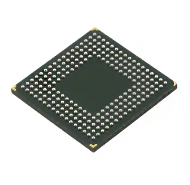
- Part No.:
- 70V3569S5BF
- Manufacturer:
- Renesas
- Category:
- Memory
- Package:
- 208-LFBGA
- Datasheet:
-
 70V3569S5BF.pdf
- Description:
- IC SRAM 576KBIT PAR 208CABGA
- Quantity:
- Payment:

- Shipping:

Inventory:3,876
Please send an inquiry. Send us your inquiry, and we will respond immediately.
Product details
Overview
70V3569S5BF from Integrated Device Technology is a high-speed 16K × 36-bit synchronous dual-port static RAM with pipelined output, 7.5 ns cycle time (133 MHz), true dual-port architecture enabling simultaneous access to the same memory location, and independent 3.3 V or 2.5 V I/O voltage selection per port-designed for high-bandwidth inter-processor communication in telecom line cards and packet buffer applications.
For engineers reviewing the 70V3569S5BF datasheet, 70V3569S5BF pinout, 70V3569S5BF application, or 70V3569S5BF equivalent, key selection criteria include pipelined read latency, byte-selectable write capability, counter-enabled burst addressing, industrial temperature support (−40°C to +85°C), and dual-chip-enable depth expansion without external logic.
Technical Context
The 70V3569S5BF implements fully synchronous operation on both ports using edge-triggered registers for address, data, and all control inputs-including R/W, CE0/CE1, BE0–BE3, ADS, CNTEN, and CNTRST-enabling precise timing control at 133 MHz. Its pipelined output mode introduces one-cycle latency between clock edge and valid data output, while self-timed write logic maintains fast cycle time independent of bus turnaround.
Each port supports independent I/O voltage configuration via OPTL/OPTR pins, allowing mixed-voltage interfacing: VDDQ can be set to 3.3 V (±150 mV) or 2.5 V (±125 mV) per port, while core VDD remains fixed at 3.3 V (±150 mV). The device integrates separate 9-bit byte enables (BE0–BE3) per port for fine-grained 36-bit bus matching and multiplexed data path compatibility.
Key Specifications
| Parameter | Value and Actual Design Meaning |
|---|---|
| Memory Organization | 16K × 36 bits (576 Kbit total); supports concurrent left/right port access to identical addresses without arbitration logic. |
| Cycle Time (Pipelined) | 7.5 ns minimum - enables 133 MHz system clocking and 9.6 Gbps aggregate bandwidth across both ports. |
| Access Time (Clock-to-Data) | 5 ns maximum - guarantees deterministic read latency for real-time packet processing pipelines. |
| Operating Temperature | −40°C to +85°C - qualified for industrial-grade deployment in base station equipment and ruggedized networking hardware. |
| I/O Voltage Flexibility | Selectable 3.3 V or 2.5 V per port via OPTL/OPTR - eliminates level-shifting components when interfacing with mixed-voltage FPGAs or ASICs. |
| Power Supply | Single 3.3 V ±150 mV core (VDD); dual independent I/O supplies (VDDQL/VDDQR) configurable per port - simplifies PCB power domain partitioning. |
| Standby Current (Full) | 6 mA typical (ISB3) - enables low-power idle states during traffic lulls without sacrificing wake-up latency. |
Pinout & Package
70V3569S5BF is packaged in a 208-pin Plastic Quad Flatpack (PQFP) with 0.5 mm lead pitch and 28 mm × 28 mm body size. Pin assignments are symmetrically organized for left (L) and right (R) ports, with dedicated VDD, VSS, VDDQL, VDDQR, OPTL, OPTR, and NC pins as defined in IDT DSC 4831 Rev. 15.
| Pin/Terminal | Circuit Role | Design Meaning |
|---|---|---|
| CLKL / CLKR | Port-synchronous clock input | Edge-triggered register clock for all inputs/outputs on respective port; enables strict timing predictability at 133 MHz. |
| A0L–A13L / A0R–A13R | Address inputs (14-bit) | Directly select one of 16K locations; ADSL/ADSR allows address strobe override for counter-based sequential access. |
| I/O0L–I/O35L / I/O0R–I/O35R | Bidirectional data I/O (36-bit) | Full 36-bit parallel interface per port; byte enables (BE0–BE3) allow independent 9-bit segment writes without read-modify-write. |
| BE0L–BE3L / BE0R–BE3R | Byte enable controls | Four active-low signals controlling 9-bit byte lanes (0–8, 9–17, 18–26, 27–35); enables partial writes and bus-width adaptation. |
| OPTL / OPTR | I/O voltage option select | Logic-level input determining VDDQL/VDDQR operating voltage: VIH = 3.3 V, VIL = 2.5 V - configures interface voltage per port independently. |
| CE0L/CE1L / CE0R/CE1R | Dual chip enable pair | Two enables per port allow depth expansion (e.g., stacking multiple devices) without external decode logic - CE0L+CE1L = active-low decode. |
Key Features
| Feature | Design Value |
|---|---|
| True dual-port memory cells | Enables simultaneous, independent read/write operations on same address - eliminates arbitration overhead in co-processor or DMA buffer designs. |
| Pipelined output mode | Guarantees deterministic 1-cycle output latency - simplifies timing closure in high-speed synchronous systems like ATM/SONET framers. |
| Independent port voltage selection | OPTL/OPTR pins configure each port for 3.3 V or 2.5 V I/O - avoids level shifters when connecting to heterogeneous logic families. |
| Address counter with reset | CNTENL/CNTENR and CNTRSTL/CNTRSTR enable auto-incrementing burst reads/writes - reduces address bus traffic in streaming applications. |
| Separate byte controls (4 × 9-bit) | Permits granular 9-bit writes without disturbing adjacent bytes - critical for protocol header manipulation and metadata insertion. |
| Full synchronous operation | All inputs registered on rising CLK edge - eliminates setup/hold violations at 133 MHz and supports tight PCB layout constraints. |
Applications
| Telecom Packet Buffer | FPGA Co-Processor Interface |
|---|---|
|
Use Scenario: Storing incoming/outgoing Ethernet or SONET frames in carrier-grade switches where ingress and egress paths operate concurrently. IC Role / Device Role / Timing Role: Dual-port SRAM acts as zero-latency shared memory between ingress and egress ASICs, synchronized by independent clocks. Use Value: Enables full-duplex frame buffering with no arbitration delay; 133 MHz bandwidth sustains 10 Gbps line rates with headroom. |
Use Scenario: High-speed data exchange between FPGA fabric and external DSP or microcontroller in radar signal processing systems. IC Role / Device Role / Timing Role: Serves as low-latency scratchpad memory with pipelined reads, allowing FPGA to stream samples while CPU processes prior blocks. Use Value: 5 ns access time and 7.5 ns cycle time eliminate pipeline stalls; byte enables support variable-length parameter updates. |
| Industrial PLC Data Exchange | Test Equipment Pattern Memory |
|
Use Scenario: Real-time I/O mapping and state synchronization between redundant controller modules in safety-critical automation systems. IC Role / Device Role / Timing Role: Provides fault-tolerant shared memory with independent port access - one port for primary controller, one for backup. Use Value: −40°C to +85°C rating ensures reliability in harsh environments; dual CE enables seamless failover without bus contention. |
Use Scenario: Storing stimulus/response patterns in automated test equipment requiring rapid, repeatable vector playback at >100 MHz. IC Role / Device Role / Timing Role: Functions as high-speed pattern store with counter-driven sequential access - CLKR drives pattern generation, CLKL loads new vectors. Use Value: Address counter + pipelined output delivers deterministic burst throughput; 2.5 V I/O mode matches LVDS driver requirements. |
Equivalent & Alternatives
The following parts are listed as comparable options for similar dual-port SRAM applications.
| Alternative Part | Technical Difference | Application Difference | Selection Advice |
|---|---|---|---|
| CY7C1362BV33-133AXC | 16K × 36, 133 MHz, but only 3.3 V I/O; no 2.5 V option or OPT pin control; uses different pinout and lacks address counter. | Suitable for cost-sensitive 3.3 V-only systems; not viable where mixed-voltage interfacing or burst addressing is required. | Choose 70V3569S5BF when independent I/O voltage selection or counter-based sequential access is needed. |
| AS7C3316PFS-133BIN | 16K × 36, 133 MHz, commercial temp only (0°C to +70°C); no industrial grade variant; lacks pipelined output mode and byte-enable granularity. | Applicable only in non-ruggedized, temperature-controlled environments; cannot replace 70V3569S5BF in telecom or industrial deployments. | Choose 70V3569S5BF for industrial temperature support, pipelined latency control, and finer 9-bit byte enables. |
Compared with CY7C1362BV33-133AXC and AS7C3316PFS-133BIN, the 70V3569S5BF uniquely combines industrial temperature range, per-port I/O voltage configurability, pipelined output timing, and integrated address counter - making it the only option supporting mixed-voltage burst-buffer architectures in carrier-class infrastructure.
Availability
70V3569S5BF is available at Aetrix Electronics and suitable for telecom packet buffering, FPGA co-processor interfacing, and industrial PLC data exchange requiring stable component supply across extended lifecycle programs.
Supply support for 70V3569S5BF includes scheduled delivery planning, volume procurement assistance, BOM continuity management, traceable sourcing, and lifecycle availability coordination for OEM customers, industrial embedded developers, connected-device designers, and electronics production programs.
Manufacturer
Integrated Device Technology (IDT), now part of Renesas Electronics, is a fabless semiconductor company specializing in timing, memory interface, and RF power solutions for communications and computing markets.
The 70V3569S5BF belongs to IDT's high-speed synchronous dual-port SRAM product line, engineered specifically for deterministic, low-latency inter-processor communication in carrier-grade networking and real-time embedded systems.
FAQ
What is the maximum operating frequency of the 70V3569S5BF?
The 70V3569S5BF supports a minimum clock cycle time of 7.5 ns, corresponding to a maximum operating frequency of 133 MHz under industrial temperature conditions (−40°C to +85°C). This is validated across both ports simultaneously with pipelined output mode enabled and all timing parameters met per IDT DSC 4831 Rev. 15.
Does the 70V3569S5BF support independent I/O voltage levels on its two ports?
Yes, the 70V3569S5BF supports independent I/O voltage selection per port via OPTL and OPTR pins. Each port can be configured for either 3.3 V (±150 mV) or 2.5 V (±125 mV) operation by setting the respective OPT pin to VIH or VIL, while core VDD remains fixed at 3.3 V - enabling direct interfacing with mixed-voltage FPGAs or ASICs without external level shifters.
What is the function of the ADSL and ADSR pins on the 70V3569S5BF?
ADSL and ADSR are address strobe enable inputs for the left and right ports respectively. When asserted low (VIL), they cause the current address bus value to be latched into the internal address register on the next rising clock edge - overriding the internal address counter. This enables flexible mixing of external address control and counter-driven sequential access within the same operational mode of the 70V3569S5BF.
How does the address counter feature work on the 70V3569S5BF?
The 70V3569S5BF includes independent address counters per port controlled by CNTENL/CNTENR and CNTRSTL/CNTRSTR. When CNTEN is low, the counter advances on each rising CLK edge; CNTRST resets it to address 0. This allows burst-mode sequential access without external address generation logic - reducing control overhead in streaming applications such as packet buffering or test pattern playback.
What package type is used for the 70V3569S5BF?
The 70V3569S5BF is supplied in a 208-pin Plastic Quad Flatpack (PQFP) package with 0.5 mm lead pitch and 28 mm × 28 mm body dimensions. This package is explicitly designated in IDT documentation as DRG208 and supports standard surface-mount assembly processes with verified thermal and mechanical reliability for industrial applications.
70V3569S5BF Specifications
- Product attributes
- Attribute value
- Manufacturer:
- Renesas
- Series:
- -
- Package/Case:
- 208-LFBGA
- Packaging:
- Tray
- Product Status:
- Obsolete
- Programmable:
- Not Verified
- Memory Type:
- Volatile
- Memory Format:
- SRAM
- Technology:
- SRAM - Dual Port, Synchronous
- Memory Size:
- 576Kbit
- Memory Organization:
- 16K x 36
- Memory Interface:
- Parallel
- Clock Frequency:
- -
- Write Cycle Time - Word, Page:
- -
- Access Time:
- 5 ns
- Voltage - Supply:
- 3.15V ~ 3.45V
- Operating Temperature:
- 0°C ~ 70°C (TA)
- Grade:
- -
- Qualification:
- -
- Mounting Type:
- Surface Mount
- Supplier Device Package:
- 208-CABGA (15x15)
70V3569S5BF FAQ
1.How can I place an order for 70V3569S5BF through Aetrix?
Please submit a Request for Quotation (RFQ) for 70V3569S5BF on Aetrix. Our sales agent will provide a competitive quotation and guide you through the order confirmation once you accept the terms.
2.Are the price and stock information for 70V3569S5BF reliable?
The price and inventory of 70V3569S5BF are updated periodically and may fluctuate due to market conditions. Stock and pricing data are typically refreshed every 24 hours. Quotation validity for 70V3569S5BF is usually 5 days.
3.What payment methods are accepted for 70V3569S5BF?
We accept Wire Transfer, PayPal, Credit Card, Western Union, MoneyGram, and Escrow for 70V3569S5BF transactions.
Note: Certain payment methods may incur a processing fee.
4.How is shipping managed for 70V3569S5BF?
70V3569S5BF orders can be shipped via leading logistics carriers, including DHL, UPS, FedEx, TNT, or Registered Mail.
Once your 70V3569S5BF order is processed, you will receive an email with the shipment details and tracking number.
Note: Tracking information may take up to 24 hours to appear. Express delivery typically takes 3–5 business days.
5.How can I obtain technical support or documentation for 70V3569S5BF?
For technical support, including 70V3569S5BF datasheets, pinout diagrams, or application guidance, please contact our engineering support team. They can provide detailed documentation and assistance for your 70V3569S5BF requirements.
6.How does Aetrix verify that 70V3569S5BF is sourced from the original manufacturer or authorized distributors?
All 70V3569S5BF products on Aetrix are procured from qualified distributors and authorized channels. Our dedicated quality assurance team conducts strict verification, including traceability checks and, if necessary, third-party testing. This ensures that 70V3569S5BF meets industry standards.
7.What is the process for return or replacement of 70V3569S5BF?
All 70V3569S5BF units undergo pre-shipment inspection (PSI). If there is an issue with 70V3569S5BF, returns or replacements are accepted under the following conditions:
1.Quantity discrepancies, incorrect items, or visible external defects (such as breakage or corrosion), acknowledged by Aetrix.
2.The issue is reported within 90 days of delivery.
3.The 70V3569S5BF part is unused and in its original packaging.
Return procedure for 70V3569S5BF:
1.Submit a request within 90 days.
2.Obtain a Return Material Authorization (RMA) from Aetrix.
70V3569S5BF Tags

-
M24C02-WMN6TP
STMicroelectronics

-
AT24C02C-XHM-T
Microchip Technology

-
AT21CS01-STUM10-T
Microchip Technology

-
AT24C02C-SSHM-T
Microchip Technology

-
24LC01BT-I/OT
Microchip Technology

-
M24C02-FMC6TG
STMicroelectronics
-
AT24CS02-SSHM-T
Microchip Technology

-
93LC46BT-I/OT
Microchip Technology
-
AT24C04C-SSHM-T
Microchip Technology

-
24LC01BT-I/SN
Microchip Technology
-
24AA02UIDT-I/OT
Microchip Technology

-
AT24C08C-STUM-T
Microchip Technology
Tech Hub

TTL and CMOS logic families differ in thresholds, loading, output drive, power and timing. This engineering guide compares 74HC and 74HCT, calculates noise margins and checks 3.3 V/5 V compatibility.

A practical engineering guide to 3.3V and 5V logic compatibility, input thresholds, resistor dividers, translator ICs, MOSFET level shifting, I2C pull-ups, timing limits and power-sequencing risks.

The 74HC595 uses push-pull logic outputs, while the TPIC6B595 uses 50 V open-drain DMOS sinks for higher-power loads. This guide compares timing, current limits, 3.3 V interfacing, load wiring, thermal…

The 74HC595 converts serial data into eight stable parallel outputs. This guide covers pin functions, shift and storage timing, OE and MR behavior, drive-current limits, cascading, voltage compatibilit…

A technical comparison of level-sensitive latches and edge-triggered flip-flops, covering timing windows, setup and hold limits, master–slave operation, time borrowing, race-through, HDL inference and…

A D latch stores one bit while Enable controls when data can pass. This reference covers gate-level operation, truth tables, transparency, setup and hold timing, LE versus OE, common ICs and practical …

An SR latch stores one bit through cross-coupled feedback. This engineering reference covers NOR and NAND implementations, truth tables, forbidden-state recovery, gated operation, switch debouncing, fa…

Latch circuits retain one bit through feedback. This technical reference covers SR and D latches, truth tables, transparency, timing limits, latch-versus-flip-flop behavior, applications and common log…

An engineering guide to LED driver operation, constant-current and constant-voltage outputs, linear and switching topologies, dimming, IC selection, calculations, replacement compatibility, and fault c…

Operational amplifier guide covering op amp basics, feedback, ideal vs real op amps, common configurations, buffer circuits, offset, bias current, gain-bandwidth, slew rate, rail-to-rail limits and sel…


