
 My Inquiry
 My Account


Renesas 71V3559S85PFG8
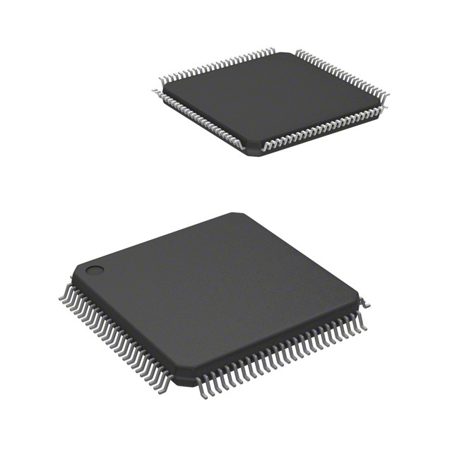
- Part No.:
- 71V3559S85PFG8
- Manufacturer:
- Renesas
- Category:
- Memory
- Package:
- 100-LQFP
- Datasheet:
-
 71V3559S85PFG8.pdf
- Description:
- IC SRAM 4.5MBIT PARALLEL 100TQFP
- Quantity:
- Payment:

- Shipping:

Inventory:1,297
Please send an inquiry. Send us your inquiry, and we will respond immediately.
Product details
Overview
71V3559S85PFG8 from Integrated Device Technology is a 3.3V synchronous ZBT™ SRAM organized as 128K x 36 (4.5 Mbit), featuring flow-through outputs, 4-word burst capability (linear or interleaved), and zero bus turnaround for seamless read/write transitions. It operates at 100 MHz with 7.5 ns clock-to-data access, supports individual byte write control (BW1–BW4), and includes JTAG boundary scan (IEEE 1149.1) and sleep mode (ZZ). Used in high-speed networking and packet buffering systems where deterministic latency and bus efficiency are critical.
For engineers reviewing the 71V3559S85PFG8 datasheet, 71V3559S85PFG8 pinout, 71V3559S85PFG8 application, or 71V3559S85PFG8 equivalent, key selection criteria include its 100-pin TQFP package, synchronous 3.3V I/O and core supply, burst counter architecture, flow-through output timing, and support for linear/interleaved burst ordering via LBO - all essential for cache coherency and memory controller interface design.
Technical Context
The 71V3559S85PFG8 implements a synchronous dual-edge-triggered address/control register pipeline with flow-through data outputs - eliminating output registers to reduce read latency. Its internal burst counter advances on ADV/LD = HIGH, enabling four consecutive data cycles per address load without external sequencing logic.
It uses three chip enables (CE1, CE2 active-low; CE2 active-high) for flexible depth expansion, supports asynchronous OE for output tri-state control, and integrates optional IEEE 1149.1 JTAG test circuitry with TMS/TDI/TCK/TDO/TRST pins. Sleep mode (ZZ) gates the internal clock to minimize power while retaining data.
Key Specifications
| Parameter | Value and Actual Design Meaning |
|---|---|
| Memory Organization | 128K × 36 bits (4.5 Mbit); supports 256K × 18 in same family but this variant is fixed 128K × 36 |
| Clock Frequency | 100 MHz maximum - enables 10 ns cycle time for high-bandwidth memory access in telecom and switch fabric applications |
| Access Time | 7.5 ns clock-to-data - defines minimum latency from CLK rising edge to valid output data in read cycles |
| Supply Voltages | VDD = 3.3 V ±5% (core), VDDQ = 3.3 V ±5% (I/O) - requires separate low-noise regulation for signal integrity |
| Burst Capability | 4-word burst with programmable order (LBO pin selects linear vs. interleaved) - reduces address bus traffic and controller overhead |
| Byte Write Control | BW1–BW4 enable independent 9-bit byte writes - allows partial-word updates without read-modify-write sequences |
| Operating Temperature | –40°C to +85°C (industrial grade) - qualified for embedded infrastructure and base station environments |
Pinout & Package
Packaged in a JEDEC-standard 100-pin thin quad flatpack (TQFP), 14 mm × 20 mm body, 0.5 mm pitch. Pin 64 supports ZZ (sleep mode) on latest die revisions; pins 83–84 reserved for future density extensions.
| Pin/Terminal | Circuit Role | Design Meaning |
|---|---|---|
| A0–A17 | Address Inputs | Synchronous inputs latched on rising CLK edge when ADV/LD = LOW and chip enabled - 18-bit address space for 128K × 36 configuration |
| CE1, CE2, CE2 | Chip Enables | Three independent enables (CE1/CE2 active-low, CE2 active-high) allow hierarchical memory decoding and depth expansion without external logic |
| R/W | Read/Write Control | Synchronous signal defining cycle type; determines whether loaded address initiates read or write one cycle later |
| ADV/LD | Advance Burst / Load Address | LOW loads new external address; HIGH increments internal burst counter - enables burst chaining without address bus activity |
| LBO | Linear/Interleaved Burst Order | Static input selecting burst sequence (LBO = LOW → linear; HIGH → interleaved) - matches CPU or DMA burst patterns |
| BW1–BW4 | Byte Write Enables | Active-low enables for four 9-bit data bytes - permits granular writes to avoid corrupting adjacent data in shared-memory systems |
| ZZ | Sleep Mode Input | Active-high signal that gates internal clock and reduces power consumption while preserving memory contents - pin 64 in TQFP |
| TMS/TDI/TCK/TDO/TRST | JTAG Test Interface | IEEE 1149.1-compliant boundary scan chain - enables production testing and in-system debug without dedicated test pads |
Key Features
| Feature | Design Value |
|---|---|
| ZBT™ Zero Bus Turnaround | Eliminates dead cycles between read and write operations - enables back-to-back memory transactions without bus idle time |
| Flow-Through Outputs | No output register; data appears on I/O pins one clock cycle after read initiation - reduces read latency versus registered-output SRAMs |
| Internally Synchronized OE | OE is asynchronous but internally synchronized to CLK - prevents metastability while allowing simple external control |
| Single R/W Pin | Replaces separate RD/WR signals - simplifies memory controller interface and reduces pin count on ASIC/FPGA designs |
| Individual Byte Write | Four independent BWx pins enable selective 9-bit writes - avoids full-word overwrites in multi-processor shared-memory systems |
Applications
| Packet Buffering in Switch Fabric | Cache Coherence Directory Storage |
|---|---|
Use Scenario: High-speed Ethernet switch buffers incoming/outgoing packets before forwarding decisions. IC Role / Device Role / Timing Role: Acts as low-latency, burst-capable packet memory with deterministic 7.5 ns read access and zero-turnaround writes. Use Value: Enables line-rate packet processing by eliminating bus idle cycles during mixed read/write traffic typical in cut-through switching. | Use Scenario: Storing cache coherency state (MESI tags) across multiple processor cores in SMP systems. IC Role / Device Role / Timing Role: Provides fast, byte-selectable SRAM for tag directory updates and lookups with minimal latency impact on cache miss handling. Use Value: Supports concurrent tag reads and partial writes via BW1–BW4, reducing contention and improving scalability of multi-core cache hierarchies. |
| Baseband Processing Memory | Real-Time Protocol Stack Buffering |
Use Scenario: Temporary storage of channelized data frames in wireless baseband processors (e.g., LTE eNodeB). IC Role / Device Role / Timing Role: Serves as synchronous, burst-access buffer interfacing directly with DSP or FPGA-based frame engines. Use Value: Linear/interleaved burst modes align with TDMA slot structures; 100 MHz operation meets real-time throughput requirements. | Use Scenario: Holding fragmented TCP/IP or SCTP protocol segments prior to reassembly in embedded gateways. IC Role / Device Role / Timing Role: Functions as deterministic-latency scratchpad memory for protocol stack software running on ARM or PowerPC controllers. Use Value: Flow-through outputs and single-cycle burst reads accelerate segment retrieval; sleep mode (ZZ) reduces power during idle periods. |
Equivalent & Alternatives
The following parts are listed as comparable options for similar synchronous SRAM applications.
| Alternative Part | Technical Difference | Application Difference | Selection Advice |
|---|---|---|---|
| CY7C1371DV33-100AXC | 128K × 36, 100 MHz, but uses QDR-II architecture with separate read/write ports and no ZBT™ zero-turnaround | Requires dual-port controller logic; better suited for true simultaneous read/write workloads, not burst-oriented sequential access | Select only if system demands concurrent read/write bandwidth over deterministic turnaround latency |
| AS7C33128PFSI-10BIN | 128K × 36, 100 MHz, but lacks JTAG, burst counter, and flow-through outputs - uses conventional synchronous SRAM timing | No burst capability or LBO control; requires external address sequencing logic for multi-word transfers | Choose when JTAG testability and burst efficiency are not required, and cost sensitivity outweighs feature set |
Compared with CY7C1371DV33-100AXC and AS7C33128PFSI-10BIN, the 71V3559S85PFG8 uniquely delivers zero bus turnaround, integrated burst sequencing, and flow-through outputs - making it optimal for memory controllers prioritizing latency predictability and bus utilization over raw dual-port bandwidth.
Availability
71V3559S85PFG8 is available at Aetrix Electronics and suitable for high-speed networking equipment, industrial baseband processors, and real-time protocol stack implementations requiring stable component supply, long-term lifecycle support, and guaranteed industrial temperature operation.
Supply support for 71V3559S85PFG8 includes scheduled delivery planning, volume procurement assistance, BOM continuity management, traceable sourcing, and lifecycle availability coordination for OEM customers, industrial embedded developers, connected-device designers, and electronics production programs.
Manufacturer
Integrated Device Technology (IDT), now part of Renesas Electronics, is a fabless semiconductor company specializing in timing, memory interface, RF, and power management ICs for communications, computing, and industrial markets.
The IDT71V3559 product line was designed specifically for high-performance, low-latency memory subsystems in networking and telecom infrastructure - emphasizing burst efficiency, deterministic timing, and seamless integration with ASIC/FPGA memory controllers.
FAQ
What is the memory organization and total capacity of the 71V3559S85PFG8?
The 71V3559S85PFG8 is organized as 128K × 36 bits, delivering a total capacity of 4,718,592 bits (4.5 Mbit). This configuration is fixed for the "S" suffix variant; the related IDT71V3557S supports 256K × 18 in the same package family but is a distinct part number. The 71V3559S85PFG8 uses all 36 data bits (I/O0–I/O31 and I/OP1–I/OP4) and 18 address lines (A0–A17) to address the full array.
Does the 71V3559S85PFG8 support both linear and interleaved burst modes, and how is the selection made?
Yes, the 71V3559S85PFG8 supports both linear and interleaved burst sequences via the LBO (Linear Burst Order) pin. When LBO is driven LOW, the device executes linear bursts (A0, A1, A2, A3); when driven HIGH, it performs interleaved bursts (A0, A1, A3, A2). LBO is a static input and must remain stable during burst operation. This selection is confirmed in the Functional Block Diagram and Burst Sequence Tables of the official IDT datasheet DSC-5282/09.
What is the role of the ZZ pin on the 71V3559S85PFG8, and which package pin does it occupy?
The ZZ pin on the 71V3559S85PFG8 enables synchronous sleep mode: when asserted HIGH, it gates the internal clock and reduces power consumption while guaranteeing data retention. In the 100-pin TQFP package (PFG suffix), ZZ is assigned to pin 64 - explicitly noted in the Pin Configuration diagrams and footnotes of the datasheet. This pin is not NC in the "S" version and is functional for power management in industrial thermal environments.
How does the 71V3559S85PFG8 implement zero bus turnaround (ZBT™), and what timing benefit does it provide?
The 71V3559S85PFG8 achieves ZBT™ by eliminating dead cycles between read and write operations: a write cycle can immediately follow a read (or vice versa) without requiring bus idle time for direction change. This is enabled by its synchronous control architecture, flow-through outputs, and single R/W pin - all coordinated by the ADV/LD and CEN signals. The result is deterministic 7.5 ns clock-to-data access and continuous bus utilization, critical for packet buffering and cache coherency applications.
Is JTAG boundary scan supported on the 71V3559S85PFG8, and which pins are used?
Yes, the 71V3559S85PFG8 includes optional IEEE 1149.1-compliant JTAG boundary scan. Pins TMS, TDI, TCK, TDO, and TRST (optional reset) are dedicated to this function and appear in the 100-pin TQFP pinout (e.g., TMS = pin 91, TDI = pin 92, TCK = pin 93, TDO = pin 94, TRST = pin 95). These pins are functional in the "S" version and documented in the Pin Definitions table and Functional Block Diagram of datasheet DSC-5282/09.
71V3559S85PFG8 Specifications
- Product attributes
- Attribute value
- Manufacturer:
- Renesas
- Series:
- -
- Package/Case:
- 100-LQFP
- Packaging:
- Tape & Reel (TR)
- Product Status:
- Obsolete
- Programmable:
- Not Verified
- Memory Type:
- Volatile
- Memory Format:
- SRAM
- Technology:
- SRAM - Synchronous, SDR (ZBT)
- Memory Size:
- 4.5Mbit
- Memory Organization:
- 256K x 18
- Memory Interface:
- Parallel
- Clock Frequency:
- -
- Write Cycle Time - Word, Page:
- -
- Access Time:
- 8.5 ns
- Voltage - Supply:
- 3.135V ~ 3.465V
- Operating Temperature:
- 0°C ~ 70°C (TA)
- Grade:
- -
- Qualification:
- -
- Mounting Type:
- Surface Mount
- Supplier Device Package:
- 100-TQFP (14x14)
71V3559S85PFG8 FAQ
1.How can I place an order for 71V3559S85PFG8 through Aetrix?
Please submit a Request for Quotation (RFQ) for 71V3559S85PFG8 on Aetrix. Our sales agent will provide a competitive quotation and guide you through the order confirmation once you accept the terms.
2.Are the price and stock information for 71V3559S85PFG8 reliable?
The price and inventory of 71V3559S85PFG8 are updated periodically and may fluctuate due to market conditions. Stock and pricing data are typically refreshed every 24 hours. Quotation validity for 71V3559S85PFG8 is usually 5 days.
3.What payment methods are accepted for 71V3559S85PFG8?
We accept Wire Transfer, PayPal, Credit Card, Western Union, MoneyGram, and Escrow for 71V3559S85PFG8 transactions.
Note: Certain payment methods may incur a processing fee.
4.How is shipping managed for 71V3559S85PFG8?
71V3559S85PFG8 orders can be shipped via leading logistics carriers, including DHL, UPS, FedEx, TNT, or Registered Mail.
Once your 71V3559S85PFG8 order is processed, you will receive an email with the shipment details and tracking number.
Note: Tracking information may take up to 24 hours to appear. Express delivery typically takes 3–5 business days.
5.How can I obtain technical support or documentation for 71V3559S85PFG8?
For technical support, including 71V3559S85PFG8 datasheets, pinout diagrams, or application guidance, please contact our engineering support team. They can provide detailed documentation and assistance for your 71V3559S85PFG8 requirements.
6.How does Aetrix verify that 71V3559S85PFG8 is sourced from the original manufacturer or authorized distributors?
All 71V3559S85PFG8 products on Aetrix are procured from qualified distributors and authorized channels. Our dedicated quality assurance team conducts strict verification, including traceability checks and, if necessary, third-party testing. This ensures that 71V3559S85PFG8 meets industry standards.
7.What is the process for return or replacement of 71V3559S85PFG8?
All 71V3559S85PFG8 units undergo pre-shipment inspection (PSI). If there is an issue with 71V3559S85PFG8, returns or replacements are accepted under the following conditions:
1.Quantity discrepancies, incorrect items, or visible external defects (such as breakage or corrosion), acknowledged by Aetrix.
2.The issue is reported within 90 days of delivery.
3.The 71V3559S85PFG8 part is unused and in its original packaging.
Return procedure for 71V3559S85PFG8:
1.Submit a request within 90 days.
2.Obtain a Return Material Authorization (RMA) from Aetrix.
71V3559S85PFG8 Tags

-
M24C02-WMN6TP
STMicroelectronics

-
AT24C02C-XHM-T
Microchip Technology

-
AT21CS01-STUM10-T
Microchip Technology

-
AT24C02C-SSHM-T
Microchip Technology

-
24LC01BT-I/OT
Microchip Technology

-
M24C02-FMC6TG
STMicroelectronics
-
AT24CS02-SSHM-T
Microchip Technology

-
93LC46BT-I/OT
Microchip Technology
-
AT24C04C-SSHM-T
Microchip Technology

-
24LC01BT-I/SN
Microchip Technology
-
24AA02UIDT-I/OT
Microchip Technology

-
AT24C08C-STUM-T
Microchip Technology
Tech Hub

TTL and CMOS logic families differ in thresholds, loading, output drive, power and timing. This engineering guide compares 74HC and 74HCT, calculates noise margins and checks 3.3 V/5 V compatibility.

A practical engineering guide to 3.3V and 5V logic compatibility, input thresholds, resistor dividers, translator ICs, MOSFET level shifting, I2C pull-ups, timing limits and power-sequencing risks.

The 74HC595 uses push-pull logic outputs, while the TPIC6B595 uses 50 V open-drain DMOS sinks for higher-power loads. This guide compares timing, current limits, 3.3 V interfacing, load wiring, thermal…

The 74HC595 converts serial data into eight stable parallel outputs. This guide covers pin functions, shift and storage timing, OE and MR behavior, drive-current limits, cascading, voltage compatibilit…

A technical comparison of level-sensitive latches and edge-triggered flip-flops, covering timing windows, setup and hold limits, master–slave operation, time borrowing, race-through, HDL inference and…

A D latch stores one bit while Enable controls when data can pass. This reference covers gate-level operation, truth tables, transparency, setup and hold timing, LE versus OE, common ICs and practical …

An SR latch stores one bit through cross-coupled feedback. This engineering reference covers NOR and NAND implementations, truth tables, forbidden-state recovery, gated operation, switch debouncing, fa…

Latch circuits retain one bit through feedback. This technical reference covers SR and D latches, truth tables, transparency, timing limits, latch-versus-flip-flop behavior, applications and common log…

An engineering guide to LED driver operation, constant-current and constant-voltage outputs, linear and switching topologies, dimming, IC selection, calculations, replacement compatibility, and fault c…

Operational amplifier guide covering op amp basics, feedback, ideal vs real op amps, common configurations, buffer circuits, offset, bias current, gain-bandwidth, slew rate, rail-to-rail limits and sel…


