
 My Inquiry
 My Account


Renesas 7205L15JGI8
- Part No.:
- 7205L15JGI8
- Manufacturer:
- Renesas
- Category:
- FIFOs Memory
- Package:
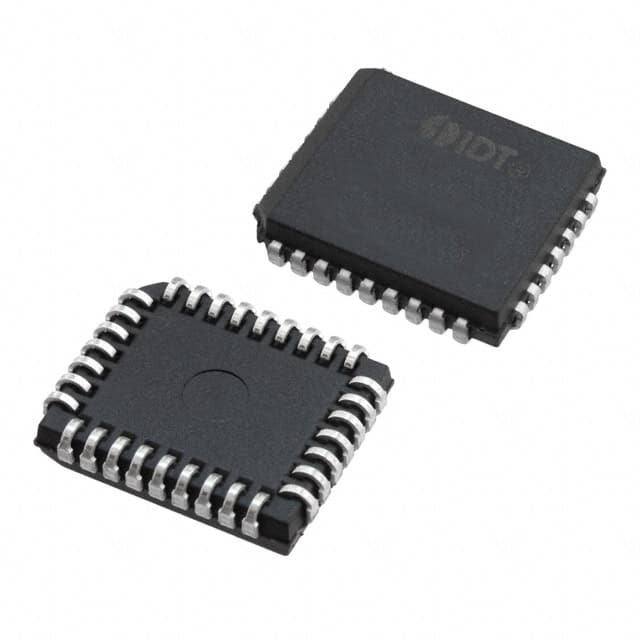
- 32-LCC (J-Lead)
- Datasheet:
-
 7205L15JGI8.pdf
- Description:
- IC FIFO ASYNC 8KX9 15NS 32PLCC
- Quantity:
- Payment:

- Shipping:

Inventory:1,501
Please send an inquiry. Send us your inquiry, and we will respond immediately.
Product details
Overview
IDT7205L15JGI8 from Integrated Device Technology is an 8,192 × 9-bit asynchronous CMOS FIFO buffer with 15 ns access time, industrial temperature range (–40°C to +85°C), and PLCC-32 package. It provides dual-port, first-in/first-out data buffering with Empty, Full, and Half-Full status flags, supporting rate-matching in serial communication interfaces between mismatched clock domains.
For engineers reviewing the IDT7205L15JGI8 datasheet, IDT7205L15JGI8 pinout, IDT7205L15JGI8 application, or IDT7205L15JGI8 equivalent, key selection considerations include its 15 ns access time, 9-bit data width with parity/control bit flexibility, retransmit capability for data replay, simultaneous asynchronous read/write operation, and compatibility within the IDT720x family for depth/width expansion.
Technical Context
The IDT7205L15JGI8 implements a fully asynchronous dual-port architecture with independent read and write pointers managed by internal logic. It uses discrete status flag outputs (EF, FF, XO/HF) to signal buffer state without requiring external control logic.
Its retransmit function resets the read pointer to the first location on a low pulse to FL/RT while preserving the write pointer - enabling deterministic data replay in protocol recovery or debugging scenarios. The device supports single-device, depth-expansion, and width-expansion modes via XI/XO and FL/RT pin configuration.
Key Specifications
| Parameter | Value and Actual Design Meaning |
|---|---|
| Memory Depth × Width | 8,192 × 9 bits - provides 73,728-bit buffer capacity for burst-mode data staging between subsystems. |
| Access Time (tA) | 15 ns max - enables reliable operation at up to ~33 MHz shift frequency in high-speed interface bridging. |
| Supply Voltage | 4.5 V to 5.5 V - compatible with standard 5 V TTL/CMOS logic families and legacy industrial power rails. |
| Operating Temperature | –40°C to +85°C - qualified for industrial environments including factory automation and motor control systems. |
| Power Consumption | Active: ≤120 mA (660 mW max); Power-down: ≤8 mA (44 mW max) - supports low-duty-cycle buffering with rapid wake-up. |
| Status Flags | EF (Empty), FF (Full), XO/HF (Expansion Out / Half-Full) - hardware-signaled boundary conditions eliminate software polling overhead. |
| Retransmit Pulse Width | 15 ns min - ensures robust triggering of read pointer reset without requiring precise timing margins from controller. |
Pinout & Package
Package: 32-lead Plastic Leaded Chip Carrier (PLCC), JEDEC standard J32-1 footprint, surface-mount compatible with industrial reflow profiles.
| Pin/Terminal | Circuit Role | Design Meaning |
|---|---|---|
| D0–D8 | Data Inputs | 9-bit parallel input bus; D0–D7 carry data, D8 optionally used for parity or control signaling. |
| Q0–Q8 | Data Outputs | Three-state outputs active only when R = LOW; high-impedance otherwise to support bus sharing. |
| W | Write Enable | Falling-edge triggered write strobe; initiates storage of D0–D8 into next FIFO location if FF = HIGH. |
| R | Read Enable | Falling-edge triggered read strobe; outputs Q0–Q8 from current read pointer location if EF = HIGH. |
| RS | Reset | Active-LOW synchronous reset that sets both read and write pointers to address zero. |
| FL/RT | First Load / Retransmit | Dual-function: LOW pulse resets read pointer to start (retransmit); HIGH enables depth expansion mode. |
| XI | Expansion In | Grounded in single-device mode; tied to XO of prior device in depth-expansion daisy chain. |
| XO/HF | Expansion Out / Half-Full Flag | In single-device mode: HF = LOW when ≥50% full; in expansion mode: pulse signals end-of-buffer to next device. |
| EF | Empty Flag | Open-drain output LOW when read pointer = write pointer - prevents invalid reads. |
| FF | Full Flag | Open-drain output LOW when write pointer wraps to read pointer - prevents overflow. |
| VCC, GND | Power Supply | Single 5 V supply; decoupling required per high-speed CMOS layout guidelines. |
Key Features
| Feature | Design Value |
|---|---|
| Asynchronous Read/Write | Independent clocks or control timing on R and W pins eliminates synchronization logic and metastability risk. |
| Retransmit Capability | Hardware-level read pointer reset via FL/RT enables deterministic replay of buffered data without host CPU intervention. |
| Expandable Architecture | Supports unlimited depth expansion (daisy-chain) and width expansion (parallel devices) using only XI/XO and FL/RT pins. |
| Flag-Driven Flow Control | EF/FF status outputs directly drive enable inputs of upstream/downstream logic, enabling autonomous handshaking. |
| Industrial Temperature Range | Qualified from –40°C to +85°C in PLCC package - suitable for uncontrolled ambient deployments without forced cooling. |
Applications
| UART Rate Matching | Motor Control Data Buffering |
|---|---|
Use Scenario: Bridging UART peripherals operating at different baud rates (e.g., 9600 bps sensor → 115200 bps MCU). IC Role / Device Role / Timing Role: Asynchronous FIFO absorbs transmit/receive bursts and prevents overrun/underrun during clock domain crossing. Use Value: Eliminates software flow control overhead and guarantees lossless data transfer across mismatched serial interfaces. | Use Scenario: Staging position feedback (encoder pulses) and command updates between motion controller and servo drive. IC Role / Device Role / Timing Role: Decouples real-time motion loop timing from variable-latency communication stacks. Use Value: Maintains deterministic jitter-free update intervals despite background communication traffic or interrupt latency. |
| Legacy Bus Interface Adapter | Protocol Analyzer Capture Buffer |
Use Scenario: Interfacing ISA or PC/104 bus peripherals to modern microcontrollers lacking native legacy timing. IC Role / Device Role / Timing Role: Synchronizes slow peripheral handshakes (e.g., /IOR, /IOW) with fast processor memory cycles. Use Value: Enables drop-in replacement of aging controllers without redesigning timing-critical glue logic. | Use Scenario: Capturing CAN or SPI transaction sequences for offline protocol validation and fault injection testing. IC Role / Device Role / Timing Role: High-speed, non-blocking capture buffer accepting continuous streams until trigger condition met. Use Value: Supports sustained 33 MHz data capture (via tA = 15 ns) with hardware-triggered stop and retransmit for repeat analysis. |
Equivalent & Alternatives
The following parts are listed as comparable options for similar FIFO buffer applications.
| Alternative Part | Technical Difference | Application Difference | Selection Advice |
|---|---|---|---|
| SN74V293-15PGG | Same 8K × 9 organization and 15 ns access, but TI's version uses 32-pin TQFP (PGG) instead of PLCC (J); VIH/VIL thresholds differ slightly. | Compatible in functional role but requires PCB layout change due to different footprint and thermal profile. | Select when TQFP assembly infrastructure is preferred and industrial temp qualification is confirmed for specific SN74V293-15PGG variant. |
| IDT7205L20JGI8 | Same PLCC-32 package and industrial temp rating, but 20 ns access time - slower timing, lower power consumption (ICC1 ≤ 100 mA). | Suitable for cost-sensitive or thermally constrained designs where 33 MHz shift frequency is not required. | Choose for reduced EMI and simpler timing margining when system throughput allows ≥20 ns cycle times. |
Compared with SN74V293-15PGG and IDT7205L20JGI8, the IDT7205L15JGI8 delivers the fastest access in the PLCC-32 industrial-grade 8K×9 FIFO family, enabling higher throughput in space-constrained legacy-compatible layouts without changing mounting method or thermal management strategy.
Availability
IDT7205L15JGI8 is available at Aetrix Electronics and suitable for UART rate matching, motor control data buffering, and legacy bus interface adapter applications requiring stable component supply across extended product lifecycles.
Supply support for IDT7205L15JGI8 includes scheduled delivery planning, volume procurement assistance, BOM continuity management, traceable sourcing, and lifecycle availability coordination for OEM customers, industrial embedded developers, connected-device designers, and electronics production programs.
Manufacturer
Integrated Device Technology (IDT), now part of Renesas Electronics, is a fabless semiconductor company specializing in timing, memory interface, RF, and high-performance interconnect solutions.
The IDT720x family was designed specifically for high-reliability, asynchronous data buffering in industrial, military, and communications equipment where deterministic latency and expandable memory depth are critical.
FAQ
What is the maximum operating frequency supported by IDT7205L15JGI8?
IDT7205L15JGI8 does not operate on a clock signal but supports a maximum shift frequency of 33.3 MHz, derived from its 15 ns access time specification. This defines the upper bound for valid read/write strobe toggle rates in asynchronous operation, assuming proper setup/hold timing compliance per AC Electrical Characteristics table.
Does IDT7205L15JGI8 support hot insertion or live swapping?
IDT7205L15JGI8 is not designed for hot insertion. Its DC and AC specifications assume stable VCC and controlled power-up sequencing. Applying signals before VCC reaches minimum operating voltage may cause undefined behavior or latch-up. Always follow recommended power-up order: VCC first, then control/data inputs.
Can IDT7205L15JGI8 be used in depth-expansion mode with mixed speed grades?
No. Depth-expansion mode requires identical access time (tA) across all devices in the chain. Mixing IDT7205L15JGI8 (15 ns) with slower variants like IDT7205L20JGI8 (20 ns) violates timing closure for XO propagation and flag synchronization, risking data corruption or metastability in boundary conditions.
Is the D8 pin strictly for parity, or can it serve other functions?
D8 is a fully functional data bit - not dedicated to parity. The datasheet notes "a bit for a control or parity at the user's option," meaning D8 may carry application-specific control information (e.g., packet delimiter, channel ID) alongside D0–D7 data, provided system logic interprets it accordingly.
How does the retransmit function interact with the Empty Flag (EF) in IDT7205L15JGI8?
During retransmit (FL/RT pulsed LOW), the read pointer resets to location zero, but EF status reflects the new relative position between read and write pointers. If the FIFO was non-empty pre-retransmit, EF remains HIGH; if write pointer = read pointer post-reset, EF goes LOW immediately. Flag validity is guaranteed after tRTF (≤25 ns) per AC specs.
7205L15JGI8 Specifications
- Product attributes
- Attribute value
- Manufacturer:
- Renesas
- Series:
- 7200
- Package/Case:
- 32-LCC (J-Lead)
- Packaging:
- Tape & Reel (TR)
- Product Status:
- Active
- Programmable:
- Not Verified
- Memory Size:
- 72K (8K x 9)
- Function:
- Asynchronous
- Data Rate:
- 40MHz
- Access Time:
- 15ns
- Voltage - Supply:
- 4.5 V ~ 5.5 V
- Current - Supply (Max):
- 120mA
- Bus Directional:
- Uni-Directional
- Expansion Type:
- Depth, Width
- Programmable Flags Support:
- No
- Retransmit Capability:
- Yes
- FWFT Support:
- No
- Operating Temperature:
- -40°C ~ 85°C
- Mounting Type:
- Surface Mount
- Supplier Device Package:
- 32-PLCC
7205L15JGI8 FAQ
1.How can I place an order for 7205L15JGI8 through Aetrix?
Please submit a Request for Quotation (RFQ) for 7205L15JGI8 on Aetrix. Our sales agent will provide a competitive quotation and guide you through the order confirmation once you accept the terms.
2.Are the price and stock information for 7205L15JGI8 reliable?
The price and inventory of 7205L15JGI8 are updated periodically and may fluctuate due to market conditions. Stock and pricing data are typically refreshed every 24 hours. Quotation validity for 7205L15JGI8 is usually 5 days.
3.What payment methods are accepted for 7205L15JGI8?
We accept Wire Transfer, PayPal, Credit Card, Western Union, MoneyGram, and Escrow for 7205L15JGI8 transactions.
Note: Certain payment methods may incur a processing fee.
4.How is shipping managed for 7205L15JGI8?
7205L15JGI8 orders can be shipped via leading logistics carriers, including DHL, UPS, FedEx, TNT, or Registered Mail.
Once your 7205L15JGI8 order is processed, you will receive an email with the shipment details and tracking number.
Note: Tracking information may take up to 24 hours to appear. Express delivery typically takes 3–5 business days.
5.How can I obtain technical support or documentation for 7205L15JGI8?
For technical support, including 7205L15JGI8 datasheets, pinout diagrams, or application guidance, please contact our engineering support team. They can provide detailed documentation and assistance for your 7205L15JGI8 requirements.
6.How does Aetrix verify that 7205L15JGI8 is sourced from the original manufacturer or authorized distributors?
All 7205L15JGI8 products on Aetrix are procured from qualified distributors and authorized channels. Our dedicated quality assurance team conducts strict verification, including traceability checks and, if necessary, third-party testing. This ensures that 7205L15JGI8 meets industry standards.
7.What is the process for return or replacement of 7205L15JGI8?
All 7205L15JGI8 units undergo pre-shipment inspection (PSI). If there is an issue with 7205L15JGI8, returns or replacements are accepted under the following conditions:
1.Quantity discrepancies, incorrect items, or visible external defects (such as breakage or corrosion), acknowledged by Aetrix.
2.The issue is reported within 90 days of delivery.
3.The 7205L15JGI8 part is unused and in its original packaging.
Return procedure for 7205L15JGI8:
1.Submit a request within 90 days.
2.Obtain a Return Material Authorization (RMA) from Aetrix.
7205L15JGI8 Tags
-
7201LA15JGI
Renesas
-
7204L12JG
Renesas

-
72V82L15PAG8
Renesas

-
7205L15JGI
Renesas
-
7208L20JG
Renesas

-
72V2105L10PFG
Renesas
-
72V2111L15PFGI
Renesas

-
72V2113L6PFG
Renesas
-
72V36110L6PFG
Renesas

-
SN74ALVC7804-40DL
Texas Instruments
-
7202LA25JGI
Renesas
-
SN74V245-15PAG
Texas Instruments
Tech Hub

A practical engineering and sourcing framework covering lifecycle verification, lifetime-buy calculations, replacement qualification, supplier checks and counterfeit-risk controls.

TTL and CMOS logic families differ in thresholds, loading, output drive, power and timing. This engineering guide compares 74HC and 74HCT, calculates noise margins and checks 3.3 V/5 V compatibility.

A practical engineering guide to 3.3V and 5V logic compatibility, input thresholds, resistor dividers, translator ICs, MOSFET level shifting, I2C pull-ups, timing limits and power-sequencing risks.

The 74HC595 uses push-pull logic outputs, while the TPIC6B595 uses 50 V open-drain DMOS sinks for higher-power loads. This guide compares timing, current limits, 3.3 V interfacing, load wiring, thermal…

The 74HC595 converts serial data into eight stable parallel outputs. This guide covers pin functions, shift and storage timing, OE and MR behavior, drive-current limits, cascading, voltage compatibilit…

A technical comparison of level-sensitive latches and edge-triggered flip-flops, covering timing windows, setup and hold limits, master–slave operation, time borrowing, race-through, HDL inference and…

A D latch stores one bit while Enable controls when data can pass. This reference covers gate-level operation, truth tables, transparency, setup and hold timing, LE versus OE, common ICs and practical …

An SR latch stores one bit through cross-coupled feedback. This engineering reference covers NOR and NAND implementations, truth tables, forbidden-state recovery, gated operation, switch debouncing, fa…

Latch circuits retain one bit through feedback. This technical reference covers SR and D latches, truth tables, transparency, timing limits, latch-versus-flip-flop behavior, applications and common log…

An engineering guide to LED driver operation, constant-current and constant-voltage outputs, linear and switching topologies, dimming, IC selection, calculations, replacement compatibility, and fault c…


