
 My Inquiry
 My Account


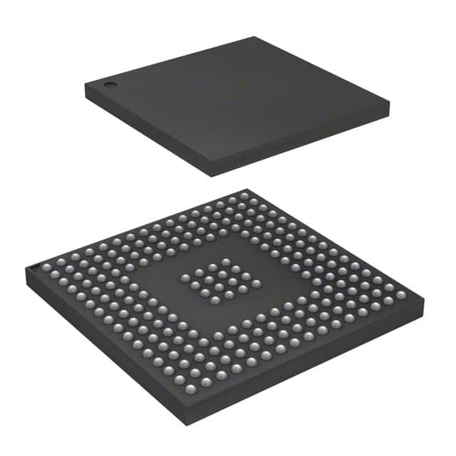
Renesas 72V71660BBG
- Part No.:
- 72V71660BBG
- Manufacturer:
- Renesas
- Category:
- Signal Switches, Multiplexers, Decoders
- Package:
- 208-BGA
- Datasheet:
-
 72V71660BBG.pdf
- Description:
- IC MULTIPLEXER SW 208PBGA
- Quantity:
- Payment:

- Shipping:

Inventory:2,236
Please send an inquiry. Send us your inquiry, and we will respond immediately.
Product details
Overview
IDT72V71660BBG from Integrated Device Technology is a 3.3 V, 16,384 × 16,384 non-blocking time slot interchange (TSI) digital switch for TDM voice/data systems. It supports 64 serial input/output streams at data rates up to 16.384 Mb/s, features per-channel variable/constant delay modes, automatic ST-BUS®/GCI interface detection, and JTAG test access. Used in carrier-grade telephony switching fabric and PCM multiplexing equipment.
For engineers reviewing the IDT72V71660BBG datasheet, IDT72V71660BBG pinout, IDT72V71660BBG application, or IDT72V71660BBG equivalent, key selection criteria include frame-aligned throughput delay control, microprocessor-accessible connection memory, per-stream input offset calibration, and 208-pin PBGA package compatibility with industrial temperature operation (–40°C to +85°C).
Technical Context
The IDT72V71660BBG implements a dual-mode TSI architecture: Variable Delay Mode achieves minimum 3-time-slot latency for voice paths, while Constant Delay Mode guarantees fixed 1-frame-plus-1-channel delay (e.g., 256 + (256 − n) + m time-slots at 16.384 Mb/s) to preserve frame integrity in data applications. Its internal Data Memory stores incoming RX stream data, and Connection Memory maps output channels to input source addresses with MOD1–0 bits selecting mode per channel.
Frame alignment is managed via dedicated hardware: FE/HCLK serves as frame evaluation input or HCLK clock depending on WFPS state; FP accepts ST-BUS®/GCI frame pulses; WFPS selects between wide-frame pulse and ST-BUS®/GCI modes. Input skew compensation uses programmable frame offset registers (FOR) with ±7.5 CLK resolution in half-cycle steps.
Key Specifications
| Parameter | Value and Actual Design Meaning |
|---|---|
| Switch Capacity | 16,384 × 16,384 non-blocking channels at 16.384 Mb/s; scales to 8,192 × 8,192 at 8.192 Mb/s, etc. |
| Serial I/O Streams | 64 RX inputs and 64 TX outputs; TX32–TX63 double as OEI0–OEI31 when Output Enable Indication enabled. |
| Data Rates | 2.048, 4.096, 8.192, or 16.384 Mb/s per stream; master clock = data rate (16.384 MHz) or 2× data rate (others). |
| Delay Modes | Per-channel selection: Variable Delay (min 3 time-slots), Constant Delay (frame-aligned, e.g., 256 + (256−n)+m slots), or high-Z. |
| Microprocessor Interface | 16-bit address (A0–A15), 16-bit data (D0–D15), CS/R/W/DS control; one-cycle random access to Data/Connection Memory. |
| JTAG Support | IEEE-1149.1 compliant TAP (TCK/TMS/TDI/TDO/TRST); enables boundary-scan testing and in-system programming. |
| Operating Temperature | –40°C to +85°C industrial range; validated for telecom infrastructure deployment. |
Pinout & Package
Package: 208-pin Plastic Ball Grid Array (PBGA), 17 mm × 17 mm, 1.0 mm pitch (order code BB). Pinout conforms to IDT72V71660 functional specification with dedicated RX/TX banks, microprocessor bus, JTAG, and control signals.
| Pin/Terminal | Circuit Role | Design Meaning |
|---|---|---|
| RX0–RX63 | Serial Data Input | 64 differential-capable CMOS inputs accepting 2.048–16.384 Mb/s TDM streams; frame-aligned by FP/FE/HCLK. |
| TX0–TX31, TX32/OEI0–TX63/OEI31 | Serial Data Output / OE Indication | Three-state CMOS outputs; TX32–TX63 repurposed as output enable status indicators when OEI=1 in Control Register. |
| A0–A15, D0–D15, CS, R/W, DS, DTA | Microprocessor Bus Interface | Standard 16-bit parallel interface; DTA asserts after each bus cycle to signal completion and enable faster read/write timing. |
| CLK, FP, FE/HCLK, WFPS | Timing & Frame Control | CLK drives serial I/O; FP detects ST-BUS®/GCI frame sync; FE/HCLK measures input skew; WFPS selects interface mode. |
| TCK, TMS, TDI, TDO, TRST | JTAG Test Access Port | Fully compliant IEEE-1149.1 interface for boundary-scan diagnostics and configuration verification. |
| ODE, RESET, ODE | Global Control | ODE enables/disables all TX drivers; RESET asynchronously clears registers and forces high-Z on TX/D0–D15; TRST initializes JTAG controller. |
Key Features
| Feature | Design Value |
|---|---|
| Per-channel delay mode selection | MOD1–0 bits in Connection Memory configure each TX channel for Variable Delay (low-latency voice), Constant Delay (frame-integrity data), or high-Z. |
| Automatic ST-BUS®/GCI detection | Hardware-level recognition of frame pulse format eliminates manual configuration and ensures interoperability with legacy and modern TDM buses. |
| Input frame offset calibration | Programmable FOR registers compensate up to +7.5 CLK of inter-stream skew-critical for distributed backplane synchronization. |
| Memory block programming | Initialize all Connection Memory bits 14–15 in two frames using BPD1–0 and MBP bits-reducing boot-time setup from seconds to microseconds. |
| Output enable indication | TX32–TX63 pins reflect real-time active/high-Z status of corresponding outputs-enabling dynamic fault monitoring without external logic. |
Applications
| Voice Over TDM Switching | PCM Multiplexer Aggregation |
|---|---|
Use Scenario: Central office TDM switch fabric routing 64 E1/T1 tributaries across multiple shelves with sub-frame latency constraints. IC Role / Device Role / Timing Role: Time slot interchange core performing per-channel cross-connect with <3-time-slot Variable Delay Mode latency. Use Value: Enables real-time voice path switching while meeting ITU-T G.114 one-way delay limits (<150 ms) at the hardware level. |
Use Scenario: Aggregating 32 × E1 (2.048 Mb/s) streams into a single 64.928 Mb/s STM-1 interface in metro access nodes. IC Role / Device Role / Timing Role: TSI-based multiplexer reordering time slots across input streams to construct contiguous payload frames. Use Value: Maintains strict frame alignment across all 64 inputs using Constant Delay Mode and automatic FP detection-ensuring SONET/SDH compatibility. |
| Distributed Radio Base Station | Legacy PBX Digital Trunk Interface |
Use Scenario: Remote radio head connecting to centralized baseband unit over CPRI-like serial links with variable propagation delay. IC Role / Device Role / Timing Role: Input skew compensator using Frame Evaluation and programmable FOR registers to align asynchronous RX streams. Use Value: Eliminates need for external delay buffers or FPGA-based alignment logic-reducing BOM cost and PCB area. |
Use Scenario: Interfacing analog/digital PBX systems with modern VoIP gateways requiring TDM-to-packet conversion. IC Role / Device Role / Timing Role: Protocol-transparent TSI bridge supporting both ST-BUS® (legacy) and GCI (modern) frame formats. Use Value: Enables drop-in replacement of aging TSI ICs without firmware or layout changes-accelerating legacy system upgrades. |
Equivalent & Alternatives
The following parts are listed as comparable options for similar time slot interchange applications.
| Alternative Part | Technical Difference | Application Difference | Selection Advice |
|---|---|---|---|
| IDT72V71260BBG | 8,192 × 8,192 capacity; same 208-pin PBGA package and pinout; identical feature set except reduced scale. | Suitable for lower-density E1-only systems (≤32 streams) where full 16K×16K capacity is unnecessary. | Select when system requires identical timing behavior and footprint but lower channel count reduces cost and power. |
| PMC-Sierra PM73120 | 16,384 × 16,384 TSI with integrated HDLC controllers and ATM cell processing; larger 256-pin PBGA package. | Targets converged TDM+packet networks; adds protocol processing not present in IDT72V71660BBG. | Choose only if HDLC/ATM offload is required; otherwise, IDT72V71660BBG offers simpler integration and lower power. |
Compared with IDT72V71260BBG, the IDT72V71660BBG delivers double switching capacity without changing board layout or software driver-ideal for scalable telecom platforms. Versus PM73120, it provides pure TSI functionality with lower complexity, power, and cost where packet processing is handled externally.
Availability
IDT72V71660BBG is available at Aetrix Electronics and suitable for telecom infrastructure, carrier-grade switching fabric, and industrial TDM equipment requiring stable component supply across long product lifecycles.
Supply support for IDT72V71660BBG includes scheduled delivery planning, volume procurement assistance, BOM continuity management, traceable sourcing, and lifecycle availability coordination for OEM customers, industrial embedded developers, connected-device designers, and electronics production programs.
Manufacturer
Integrated Device Technology (IDT), now part of Renesas Electronics, specialized in high-performance timing, memory interface, and communications ICs for networking and telecom markets.
The IDT72V71660BBG belongs to IDT's TSI digital switch family, engineered specifically for carrier-class TDM time slot interchange in voice/data multiplexers, central office switches, and radio access networks.
FAQ
What is the maximum data rate supported by the IDT72V71660BBG on each serial stream?
The IDT72V71660BBG supports serial data rates of 2.048 Mb/s, 4.096 Mb/s, 8.192 Mb/s, or 16.384 Mb/s per RX/TX stream. At 16.384 Mb/s, the master clock (CLK) runs at 16.384 MHz with one bit per clock edge; at lower rates, CLK operates at twice the data rate with two clocks per bit. This is configured via DR1–0 bits in the Control Register.
How does the IDT72V71660BBG handle input stream skew across its 64 RX channels?
The IDT72V71660BBG compensates for inter-stream skew using its Frame Evaluation (FE/HCLK) input and Frame Offset Registers (FOR). Each RX stream can be individually delayed up to +7.5 CLK periods in 0.5-cycle increments. Skew measurement is automated: setting the Start Frame Evaluation bit initiates a two-frame calibration cycle that writes the measured offset into the Frame Alignment Register.
Can the IDT72V71660BBG operate in both ST-BUS® and GCI interface modes simultaneously?
No-the IDT72V71660BBG automatically detects and locks to either ST-BUS® or GCI frame format based on the FP input signal, but it cannot process both formats concurrently. The WFPS pin selects the operational mode: LOW enables ST-BUS®/GCI auto-detection, HIGH enables Wide Frame Pulse mode. Once detected, the device configures its internal timing accordingly.
What is the function of the TX32–TX63 pins when Output Enable Indication is enabled?
When the OEI bit (bit 14) in the Control Register is set to 1, the TX32–TX63 pins cease functioning as data outputs and instead indicate the active/high-Z state of their corresponding TX0–TX31 outputs. For example, TX32 reflects OEI0 status: logic HIGH means TX0 is actively driving, LOW means TX0 is in high-impedance. This enables real-time hardware monitoring of output driver states.
Does the IDT72V71660BBG require external memory for configuration or operation?
No-the IDT72V71660BBG contains all necessary internal memory: 16,384 × 16-bit Data Memory for incoming stream storage and 16,384 × 16-bit Connection Memory for path mapping. Configuration is performed via its 16-bit microprocessor interface (A0–A15, D0–D15), and no external RAM or Flash is needed for normal operation or initialization.
72V71660BBG Specifications
- Product attributes
- Attribute value
- Manufacturer:
- Renesas
- Series:
- 72V
- Package/Case:
- 208-BGA
- Packaging:
- Tray
- Product Status:
- Active
- Type:
- Multiplexer
- Circuit:
- -
- Independent Circuits:
- 4
- Current - Output High, Low:
- -
- Voltage Supply Source:
- Single Supply
- Voltage - Supply:
- 3V ~ 3.6V
- Operating Temperature:
- -40°C ~ 85°C
- Grade:
- -
- Qualification:
- -
- Mounting Type:
- Surface Mount
- Supplier Device Package:
- 208-PBGA (17x17)
72V71660BBG FAQ
1.How can I place an order for 72V71660BBG through Aetrix?
Please submit a Request for Quotation (RFQ) for 72V71660BBG on Aetrix. Our sales agent will provide a competitive quotation and guide you through the order confirmation once you accept the terms.
2.Are the price and stock information for 72V71660BBG reliable?
The price and inventory of 72V71660BBG are updated periodically and may fluctuate due to market conditions. Stock and pricing data are typically refreshed every 24 hours. Quotation validity for 72V71660BBG is usually 5 days.
3.What payment methods are accepted for 72V71660BBG?
We accept Wire Transfer, PayPal, Credit Card, Western Union, MoneyGram, and Escrow for 72V71660BBG transactions.
Note: Certain payment methods may incur a processing fee.
4.How is shipping managed for 72V71660BBG?
72V71660BBG orders can be shipped via leading logistics carriers, including DHL, UPS, FedEx, TNT, or Registered Mail.
Once your 72V71660BBG order is processed, you will receive an email with the shipment details and tracking number.
Note: Tracking information may take up to 24 hours to appear. Express delivery typically takes 3–5 business days.
5.How can I obtain technical support or documentation for 72V71660BBG?
For technical support, including 72V71660BBG datasheets, pinout diagrams, or application guidance, please contact our engineering support team. They can provide detailed documentation and assistance for your 72V71660BBG requirements.
6.How does Aetrix verify that 72V71660BBG is sourced from the original manufacturer or authorized distributors?
All 72V71660BBG products on Aetrix are procured from qualified distributors and authorized channels. Our dedicated quality assurance team conducts strict verification, including traceability checks and, if necessary, third-party testing. This ensures that 72V71660BBG meets industry standards.
7.What is the process for return or replacement of 72V71660BBG?
All 72V71660BBG units undergo pre-shipment inspection (PSI). If there is an issue with 72V71660BBG, returns or replacements are accepted under the following conditions:
1.Quantity discrepancies, incorrect items, or visible external defects (such as breakage or corrosion), acknowledged by Aetrix.
2.The issue is reported within 90 days of delivery.
3.The 72V71660BBG part is unused and in its original packaging.
Return procedure for 72V71660BBG:
1.Submit a request within 90 days.
2.Obtain a Return Material Authorization (RMA) from Aetrix.
72V71660BBG Tags

-
SN74HC138DR
Texas Instruments
-
TC7SB3157CFU,LF(CT
Toshiba Semiconductor and Storage
-
74CBTLV3257PW,118
Nexperia USA Inc.

-
SN74CBTLV3257PWR
Texas Instruments
-
74CBTLV3257GUX
Nexperia USA Inc.
-
74HC154BQ,118
Nexperia USA Inc.

-
P3S0200GMX
NXP USA Inc.

-
SN74CB3Q3245PWR
Texas Instruments
-
SN74CB3Q3257RGYR
Texas Instruments

-
TCA9543APWR
Texas Instruments
-
TCA9546APWR
Texas Instruments

-
SN74HC138N
Texas Instruments
Tech Hub

TTL and CMOS logic families differ in thresholds, loading, output drive, power and timing. This engineering guide compares 74HC and 74HCT, calculates noise margins and checks 3.3 V/5 V compatibility.

A practical engineering guide to 3.3V and 5V logic compatibility, input thresholds, resistor dividers, translator ICs, MOSFET level shifting, I2C pull-ups, timing limits and power-sequencing risks.

The 74HC595 uses push-pull logic outputs, while the TPIC6B595 uses 50 V open-drain DMOS sinks for higher-power loads. This guide compares timing, current limits, 3.3 V interfacing, load wiring, thermal…

The 74HC595 converts serial data into eight stable parallel outputs. This guide covers pin functions, shift and storage timing, OE and MR behavior, drive-current limits, cascading, voltage compatibilit…

A technical comparison of level-sensitive latches and edge-triggered flip-flops, covering timing windows, setup and hold limits, master–slave operation, time borrowing, race-through, HDL inference and…

A D latch stores one bit while Enable controls when data can pass. This reference covers gate-level operation, truth tables, transparency, setup and hold timing, LE versus OE, common ICs and practical …

An SR latch stores one bit through cross-coupled feedback. This engineering reference covers NOR and NAND implementations, truth tables, forbidden-state recovery, gated operation, switch debouncing, fa…

Latch circuits retain one bit through feedback. This technical reference covers SR and D latches, truth tables, transparency, timing limits, latch-versus-flip-flop behavior, applications and common log…

An engineering guide to LED driver operation, constant-current and constant-voltage outputs, linear and switching topologies, dimming, IC selection, calculations, replacement compatibility, and fault c…

Operational amplifier guide covering op amp basics, feedback, ideal vs real op amps, common configurations, buffer circuits, offset, bias current, gain-bandwidth, slew rate, rail-to-rail limits and sel…


