
 My Inquiry
 My Account


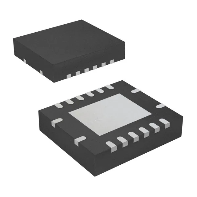
Nexperia USA Inc. 74AUP1G19GS,132

- Part No.:
- 74AUP1G19GS,132
- Manufacturer:
- Nexperia USA Inc.
- Category:
- Signal Switches, Multiplexers, Decoders
- Package:
- 6-XFDFN
- Datasheet:
-
 74AUP1G19GS,132.pdf
- Description:
- IC DECODER/DEMUX 1 X 1:2 6XSON
- Quantity:
- Payment:

- Shipping:

Inventory:1,662
Please send an inquiry. Send us your inquiry, and we will respond immediately.
Product details
Overview
74AUP1G19GS,132 from Nexperia is a low-power 1-of-2 decoder/demultiplexer with active-low enable (E), true (1Y) and complement (2Y) outputs, Schmitt-trigger inputs, IOFF partial power-down support, and operation across 0.8 V to 3.6 V supply. It buffers input A to both outputs when E is LOW and forces both outputs HIGH when E is HIGH-used in voltage-level-flexible signal routing for portable sensors and battery-powered microcontroller I/O expansion.
For engineers reviewing the 74AUP1G19GS,132 datasheet, 74AUP1G19GS,132 pinout, 74AUP1G19GS,132 application, or 74AUP1G19GS,132 equivalent, key selection factors include its ultra-low ICC (≤1.4 µA at +125 °C), IOFF leakage (±0.75 µA at VCC = 0 V), 6-terminal XSON6 package (SOT1202), Schmitt-trigger noise immunity, and guaranteed operation from –40 °C to +125 °C.
Technical Context
This device implements a single-input, dual-output decoding function with asynchronous enable control. Its Schmitt-trigger inputs tolerate slow-rising/falling signals up to 200 ns/V transition rate, and the IOFF circuit actively disables outputs during power-down to prevent backflow current when VCC = 0 V.
The logic behavior is strictly defined by its truth table: E = L enables pass-through of A to 1Y (true) and 2Y (complement); E = H forces both outputs high regardless of A. Propagation delay ranges from 1.0 ns (VCC = 3.3 V, CL = 5 pF) to 3.9 ns (–40 °C to +125 °C, same conditions), ensuring timing predictability in mixed-voltage systems.
Key Specifications
| Parameter | Value and Actual Design Meaning |
|---|---|
| Supply Voltage Range | 0.8 V to 3.6 V - supports direct interface with 0.9 V, 1.2 V, 1.8 V, 2.5 V, and 3.3 V logic domains without level shifters. |
| Max ICC (Static) | 1.4 µA at +125 °C - enables multi-year battery life in always-on sensor nodes and IoT endpoints. |
| IOFF Leakage | ±0.75 µA at VCC = 0 V - prevents damaging back-current when host MCU powers down while peripheral rails remain active. |
| Input Thresholds | VIL ≤ 0.30×VCC, VIH ≥ 0.70×VCC at +125 °C - ensures robust noise margin across full voltage and temperature range. |
| Propagation Delay | 1.2 ns to 3.9 ns (A→1Y/2Y, E→1Y/2Y) - meets timing closure for sub-100 MHz clock distribution and control signal fanout. |
| ESD Rating | HBM >5000 V, CDM >1000 V - survives handling and board assembly without additional protection circuitry. |
| Operating Temperature | –40 °C to +125 °C - qualified for under-hood automotive modules, industrial PLC I/O, and outdoor edge devices. |
Pinout & Package
XSON6 plastic extremely thin small outline package (no leads); 6 terminals; body dimensions 1.0 mm × 1.0 mm × 0.35 mm (SOT1202). Pin 1 indicator located on lower left corner below marking code "pY".
| Pin/Terminal | Circuit Role | Design Meaning |
|---|---|---|
| 1 - A | Data input | Single-bit address/data source routed to both outputs when enabled; Schmitt-triggered for noise resilience. |
| 2 - GND | Ground reference | 0 V return path for all internal logic and output drivers; must be low-impedance for stable IOFF operation. |
| 3 - E | Enable input (active LOW) | Asynchronous control: LOW enables decoding; HIGH forces 1Y and 2Y to HIGH-Z-equivalent state (both outputs HIGH). |
| 4 - 2Y | Complement output | Active-high inverted copy of A when E = LOW; driven to VOH/VOL per load and VCC; disabled (HIGH) when E = HIGH. |
| 5 - VCC | Supply voltage | Power rail for logic core and output buffers; supports dynamic voltage scaling from 0.8 V to 3.6 V. |
| 6 - 1Y | True output | Active-high non-inverted copy of A when E = LOW; synchronized with 2Y; exhibits identical propagation delay and drive strength. |
Key Features
| Feature | Design Value |
|---|---|
| Ultra-low static power | ICC ≤ 1.4 µA at +125 °C ensures negligible quiescent drain in always-on monitoring circuits. |
| IOFF partial power-down | Outputs fully disabled with ±0.75 µA leakage when VCC = 0 V - critical for hot-swap and multi-rail system safety. |
| Schmitt-trigger inputs | Input hysteresis >0.3×VCC eliminates chatter on slow or noisy control lines like mechanical switch debouncing. |
| Overvoltage-tolerant inputs | Accepts up to 3.6 V regardless of VCC setting - allows interfacing with higher-voltage peripherals without external clamping. |
| Wide temperature qualification | Specified from –40 °C to +125 °C - validated for automotive engine control units and industrial motor drives. |
Applications
| Portable Sensor Hub | Low-Power MCU I/O Expansion |
|---|---|
|
Use Scenario: A wearable health monitor uses an ARM Cortex-M0+ MCU (1.8 V I/O) to manage multiple analog sensors (3.3 V supply) via shared data lines. IC Role / Device Role / Timing Role: 74AUP1G19GS,132 acts as a voltage-agnostic demux to route MCU GPIO signals to individual sensor enable lines, with E controlled by firmware. Use Value: Eliminates need for discrete level shifters; IOFF prevents reverse current when MCU sleeps and sensor rails stay live. |
Use Scenario: An industrial temperature logger employs a battery-backed MSP430 with limited GPIO, requiring dynamic allocation of one pin to control two separate alarm LEDs. IC Role / Device Role / Timing Role: Functions as a 1-to-2 decoder: MCU GPIO drives A, firmware toggles E to select which LED (1Y or 2Y) receives the signal. Use Value: Reduces BOM count vs. discrete transistors; Schmitt inputs reject noise from long PCB traces to remote LED assemblies. |
| Automotive Body Control Module | USB-C Power Delivery Sequencing |
|
Use Scenario: A BCM controls interior lighting and mirror heaters using a 3.3 V microcontroller, but heater drivers require 5 V logic-level enable signals. IC Role / Device Role / Timing Role: Serves as a buffered decoder: MCU GPIO (3.3 V) drives A; E tied LOW; 1Y drives lighting driver, 2Y drives heater driver. Use Value: Overvoltage-tolerant inputs accept 3.3 V safely while driving 5 V-tolerant loads; low ICC extends vehicle parasitic draw budget. |
Use Scenario: A USB-C PD controller (1.2 V core) sequences power delivery by enabling VBUS and CC line configuration ICs in strict order. IC Role / Device Role / Timing Role: Provides dual, synchronized enable signals: A = PD controller output, E = system ready flag, 1Y/2Y trigger downstream ICs. Use Value: Guaranteed propagation matching (<0.3 ns skew between 1Y/2Y) ensures deterministic power-up sequence timing. |
Equivalent & Alternatives
The following parts are listed as comparable options for similar 1-of-2 decoder/demultiplexer applications.
| Alternative Part | Technical Difference | Application Difference | Selection Advice |
|---|---|---|---|
| SN74LVC1G19DBVR | Wider VCC range (1.65 V–5.5 V); no IOFF; higher ICC (10 µA typical); standard SOT-23-6 package. | Lacks power-down isolation; unsuitable for multi-rail hot-swap systems where VCC may be unpowered. | Select only if operating exclusively above 1.65 V and IOFF is not required. |
| 74LVC1G19GW,125 | Same AUP family but TSSOP6 (SOT363-2) package; identical electrical specs; larger footprint (2.2 mm × 1.3 mm vs. 1.0 mm × 1.0 mm). | Less suitable for space-constrained wearables or miniaturized modules where board area is premium. | Choose only when hand-soldering or legacy PCB layout requires TSSOP6 compatibility. |
Compared with SN74LVC1G19DBVR and 74LVC1G19GW,125, the 74AUP1G19GS,132 uniquely delivers sub-µA static current, certified IOFF protection, and the smallest XSON6 footprint-making it optimal for battery-critical, multi-voltage, and miniaturized designs.
Availability
74AUP1G19GS,132 is available at Aetrix Electronics and suitable for portable sensor hubs, low-power MCU I/O expansion, automotive body control modules, and USB-C power delivery sequencing requiring stable component supply across extended temperature and voltage ranges.
Supply support for 74AUP1G19GS,132 includes scheduled delivery planning, volume procurement assistance, BOM continuity management, traceable sourcing, and lifecycle availability coordination for OEM customers, industrial embedded developers, connected-device designers, and electronics production programs.
Manufacturer
Nexperia is a leading semiconductor expert in high-volume, high-reliability logic, analog, and MOSFET solutions, headquartered in Nijmegen, Netherlands, serving automotive, industrial, and consumer markets globally.
The 74AUP (Advanced Ultra-low Power) product line targets energy-constrained applications demanding nanowatt static power, wide VCC scalability, and robust IOFF protection-designed specifically for battery-powered and thermally sensitive systems.
FAQ
Can 74AUP1G19GS,132 operate with VCC = 0.8 V while driving a 3.3 V-tolerant load?
Yes. Its overvoltage-tolerant inputs accept up to 3.6 V regardless of VCC, and outputs swing rail-to-rail (VOH ≈ VCC, VOL < 0.1 V) at 0.8 V. The load must interpret 0.8 V as valid HIGH and 0 V as valid LOW per its own input thresholds-verified for 3.3 V CMOS loads with VIH > 2.0 V and VIL < 0.9 V.
What happens to outputs 1Y and 2Y when VCC is removed but A and E remain at 3.3 V?
With VCC = 0 V, the IOFF circuit activates, disabling both outputs. Measured IOFF leakage is ±0.75 µA maximum-preventing harmful back-current into the unpowered device. Neither 1Y nor 2Y sources or sinks significant current, preserving system integrity during partial power-down.
Is the propagation delay matched between 1Y and 2Y outputs?
Yes. Per datasheet Table 8, tPLH and tPHL are identical for A→1Y and A→2Y paths under identical test conditions (CL, VCC, temperature). Skew is specified as ≤0.3 ns across all operating ranges, enabling use in synchronous dual-output applications like complementary clock gating.
Does the Schmitt-trigger input eliminate the need for external RC filtering on noisy switch inputs?
Yes. With typical hysteresis >0.3×VCC (e.g., ~0.9 V at 3.0 V VCC), the Schmitt action rejects noise spikes <1.5× the hysteresis window. This allows direct connection of mechanical switches or long cables without external debounce components-reducing BOM cost and board area.
74AUP1G19GS,132 Specifications
- Product attributes
- Attribute value
- Manufacturer:
- Nexperia USA Inc.
- Series:
- 74AUP
- Package/Case:
- 6-XFDFN
- Packaging:
- Tape & Reel (TR)
- Product Status:
- Active
- Type:
- Decoder/Demultiplexer
- Circuit:
- 1 x 1:2
- Independent Circuits:
- 1
- Current - Output High, Low:
- 4mA, 4mA
- Voltage Supply Source:
- Single Supply
- Voltage - Supply:
- 0.8V ~ 3.6V
- Operating Temperature:
- -40°C ~ 125°C (TA)
- Grade:
- -
- Qualification:
- -
- Mounting Type:
- Surface Mount
- Supplier Device Package:
- 6-XSON, SOT1202 (1x1)
74AUP1G19GS,132 FAQ
1.How can I place an order for 74AUP1G19GS,132 through Aetrix?
Please submit a Request for Quotation (RFQ) for 74AUP1G19GS,132 on Aetrix. Our sales agent will provide a competitive quotation and guide you through the order confirmation once you accept the terms.
2.Are the price and stock information for 74AUP1G19GS,132 reliable?
The price and inventory of 74AUP1G19GS,132 are updated periodically and may fluctuate due to market conditions. Stock and pricing data are typically refreshed every 24 hours. Quotation validity for 74AUP1G19GS,132 is usually 5 days.
3.What payment methods are accepted for 74AUP1G19GS,132?
We accept Wire Transfer, PayPal, Credit Card, Western Union, MoneyGram, and Escrow for 74AUP1G19GS,132 transactions.
Note: Certain payment methods may incur a processing fee.
4.How is shipping managed for 74AUP1G19GS,132?
74AUP1G19GS,132 orders can be shipped via leading logistics carriers, including DHL, UPS, FedEx, TNT, or Registered Mail.
Once your 74AUP1G19GS,132 order is processed, you will receive an email with the shipment details and tracking number.
Note: Tracking information may take up to 24 hours to appear. Express delivery typically takes 3–5 business days.
5.How can I obtain technical support or documentation for 74AUP1G19GS,132?
For technical support, including 74AUP1G19GS,132 datasheets, pinout diagrams, or application guidance, please contact our engineering support team. They can provide detailed documentation and assistance for your 74AUP1G19GS,132 requirements.
6.How does Aetrix verify that 74AUP1G19GS,132 is sourced from the original manufacturer or authorized distributors?
All 74AUP1G19GS,132 products on Aetrix are procured from qualified distributors and authorized channels. Our dedicated quality assurance team conducts strict verification, including traceability checks and, if necessary, third-party testing. This ensures that 74AUP1G19GS,132 meets industry standards.
7.What is the process for return or replacement of 74AUP1G19GS,132?
All 74AUP1G19GS,132 units undergo pre-shipment inspection (PSI). If there is an issue with 74AUP1G19GS,132, returns or replacements are accepted under the following conditions:
1.Quantity discrepancies, incorrect items, or visible external defects (such as breakage or corrosion), acknowledged by Aetrix.
2.The issue is reported within 90 days of delivery.
3.The 74AUP1G19GS,132 part is unused and in its original packaging.
Return procedure for 74AUP1G19GS,132:
1.Submit a request within 90 days.
2.Obtain a Return Material Authorization (RMA) from Aetrix.
74AUP1G19GS,132 Tags

-
SN74HC138DR
Texas Instruments
-
TC7SB3157CFU,LF(CT
Toshiba Semiconductor and Storage
-
74CBTLV3257PW,118
Nexperia USA Inc.

-
SN74CBTLV3257PWR
Texas Instruments
-
74CBTLV3257GUX
Nexperia USA Inc.
-
74HC154BQ,118
Nexperia USA Inc.

-
P3S0200GMX
NXP USA Inc.

-
SN74CB3Q3245PWR
Texas Instruments
-
SN74CB3Q3257RGYR
Texas Instruments

-
TCA9543APWR
Texas Instruments
-
TCA9546APWR
Texas Instruments

-
SN74HC138N
Texas Instruments
Tech Hub

An engineering guide to LED driver operation, constant-current and constant-voltage outputs, linear and switching topologies, dimming, IC selection, calculations, replacement compatibility, and fault c…

Operational amplifier guide covering op amp basics, feedback, ideal vs real op amps, common configurations, buffer circuits, offset, bias current, gain-bandwidth, slew rate, rail-to-rail limits and sel…

Jumper cables guide covering safe connection order, red and black clamp placement, final ground connection, cable gauge, length, clamp quality, copper vs CCA cables, jump starter comparison and battery…

LDO regulator guide covering low dropout voltage, power dissipation, thermal design, PSRR, output noise, capacitor stability, adjustable LDO circuits, LDO vs buck converter and datasheet selection chec…

Conditional Access Module guide covering CAM meaning, CI/CI+ interface, smart card authorization, DVB security workflow, TV and set-top box compatibility, internal electronics, ESD protection, connecto…

Guide to electronic component obsolescence covering EOL risk, PCN/PDN notices, last-time buy planning, replacement options, form-fit-function validation, counterfeit risk and BOM lifecycle management.

18650 battery guide covering lithium-ion cell basics, 3.6V/3.7V voltage, 4.2V charging, mAh and Wh capacity, protected cells, chargers, BMS, series-parallel packs, holders, welding and sourcing checks.…

Hall effect sensor guide covering working principle, linear and digital sensors, Arduino circuits, current sensing, speed detection, automotive applications, A3144 examples, signal filtering and datash…

Product Change Notification guide for electronic components, covering PCN meaning, PCN vs PDN/EOL, common change types, risk levels, form-fit-function review, engineering validation, BOM control, LTB/L…

A practical guide to blend door actuators, covering HVAC function, symptoms, location, AC and heater issues, reset and calibration, replacement cost, electrical diagnosis, compatibility checks, and rep…


