
 My Inquiry
 My Account


Nexperia USA Inc. 74AUP3G3404GSX
- Part No.:
- 74AUP3G3404GSX
- Manufacturer:
- Nexperia USA Inc.
- Package:
- 8-XFDFN
- Datasheet:
-
 74AUP3G3404GSX.pdf
- Description:
- IC DUAL BUFFER SGL INVERT X2SON8
- Quantity:
- Payment:

- Shipping:

Inventory:4,869
Please send an inquiry. Send us your inquiry, and we will respond immediately.
Product details
Overview
74AUP3G3404 from Nexperia is a low-power triple-gate logic device integrating two non-inverting buffers (1A→1Y, 2A→2Y) and one inverting buffer (3A→3Y), with Schmitt-trigger inputs enabling robust noise immunity across 0.8 V–3.6 V supply operation. It delivers ICC ≤ 0.9 μA max static current, IOFF-enabled partial power-down protection, and propagation delays as low as 1.1 ns (VCC = 3.0–3.6 V, CL = 5 pF), targeting battery-powered sensor interfaces and I/O level-shifting in portable industrial controllers.
For engineers reviewing the 74AUP3G3404 datasheet, 74AUP3G3404 pinout, 74AUP3G3404 application, or 74AUP3G3404 equivalent, key selection criteria include its dual-buffer + inverter topology, ultra-low ICC at sub-1-V operation, IOFF leakage < ±0.75 μA during power-down, and guaranteed Schmitt-trigger hysteresis across full VCC range - critical for noisy microcontroller GPIO expansion and legacy signal conditioning.
Technical Context
This device implements three independent logic gates in a single 8-terminal XSON package: two identical non-inverting buffers (1Y, 2Y) and one inverting buffer (3Y), each with Schmitt-trigger inputs ensuring clean switching despite slow-rising or noisy signals. All inputs tolerate voltages up to 3.6 V regardless of VCC, supporting mixed-voltage domain interfacing.
The IOFF circuit actively disables outputs when VCC = 0 V, limiting backflow current to ±0.75 μA maximum and enabling safe hot-insertion in partial-power-down systems. Propagation delay varies from 1.1 ns (3.6 V, 5 pF) to 33.6 ns (0.8 V, 30 pF), with CPD = 4.0 pF at 3.6 V enabling precise dynamic power estimation via PD = CPD × VCC² × fi × N.
Key Specifications
| Parameter | Value and Actual Design Meaning |
|---|---|
| VCC Range | 0.8 V to 3.6 V - enables direct interface with 0.9 V, 1.2 V, 1.8 V, 2.5 V, and 3.3 V logic domains without level shifters |
| ICC (max) | 0.9 μA at TA = −40 °C to +125 °C - ensures multi-year battery life in always-on IoT endpoint nodes |
| tpd (min) | 1.1 ns at VCC = 3.0–3.6 V, CL = 5 pF - supports >200 MHz toggle rates in high-speed control loops |
| IOFF Leakage | ±0.75 μA max at VCC = 0 V - prevents damaging backfeed current during system sleep or hot-swap events |
| VIH/VIL Hysteresis | Guaranteed Schmitt-trigger action across full VCC - eliminates chatter on slow RC-debounced switch inputs |
| ESD Rating | HBM >5000 V, CDM >1000 V - meets IEC 61000-4-2 Level 4 for industrial board-level ESD resilience |
| Operating Temp | −40 °C to +125 °C - qualified for under-hood automotive body control modules and industrial PLC I/O cards |
Pinout & Package
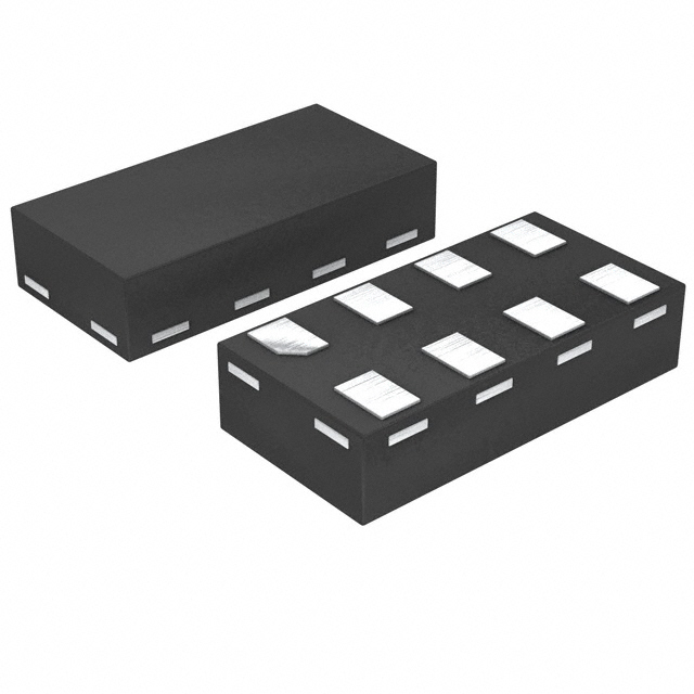
XSON8 package (SOT1203): 1.35 mm × 1.0 mm × 0.35 mm body, no leads, 8 exposed terminals, moisture sensitivity level 1, reflow-compatible.
| Pin/Terminal | Circuit Role | Design Meaning |
|---|---|---|
| 1 | 1A | Input to first non-inverting buffer - accepts 0–3.6 V regardless of VCC; Schmitt-triggered |
| 2 | 3Y | Output of inverting buffer - drives loads up to ±4 mA at 3.0 V with VOL ≤ 0.45 V |
| 3 | VCC | Main supply rail - powers all three gates; IOFF active when VCC = 0 V |
| 4 | 2Y | Output of second non-inverting buffer - electrically identical to 1Y; shares same VCC/GND |
| 5 | 2A | Input to second non-inverting buffer - independent of 1A/3A; full Schmitt noise margin |
| 6 | 3A | Input to inverting buffer - inverted logic function; VIH/VIL thresholds track VCC proportionally |
| 7 | 1Y | Output of first non-inverting buffer - matches 2Y timing and drive strength |
| 8 | GND | Reference ground - must be low-impedance return path for all I/O and supply currents |
Key Features
| Feature | Design Value |
|---|---|
| Triple-gate integration | Combines two buffers and one inverter in one die - reduces PCB area by 60% vs discrete 74AUP1G34 + 74AUP1G04 solution |
| IOFF partial power-down | Outputs enter high-Z state at VCC = 0 V - enables safe insertion into live backplanes without bus contention |
| Wide-VCC Schmitt inputs | Valid hysteresis from 0.8 V to 3.6 V - eliminates external RC filters for pushbutton debouncing in wearables |
| Ultra-low ICC | 0.9 μA max at +125 °C - extends coin-cell lifetime beyond 10 years in maintenance-free sensor transmitters |
| Multi-standard compliance | JESD8-12 through JESD8-B coverage - certifies interoperability across 0.8 V to 3.6 V JEDEC logic families |
Applications
| Industrial Sensor Interface | Portable Medical Device I/O |
|---|---|
Use Scenario: Conditioning analog sensor outputs (e.g., thermistor, pressure bridge) before ADC sampling in battery-powered handheld meters. IC Role / Device Role / Timing Role: Dual buffer isolates noisy analog front-end from digital domain; inverter drives LED status indicator with precise edge timing. Use Value: Schmitt inputs reject EMI-induced glitches on long sensor traces; 0.9 μA ICC extends 200 mAh CR2032 battery life to >5 years. | Use Scenario: Expanding GPIO count on ultra-low-power MCU (e.g., ARM Cortex-M0+) in wearable ECG monitors. IC Role / Device Role / Timing Role: Buffers route touch-button interrupts; inverter toggles buzzer driver enable line synchronized to heartbeat detection. Use Value: IOFF prevents backfeed from powered buzzer circuit into MCU during sleep mode; 1.35 mm × 1.0 mm XSON8 saves critical PCB real estate. |
| Automotive Body Control Module | Smart Home Hub Signal Conditioning |
Use Scenario: Interfacing 12 V switch inputs (via resistive divider) to 3.3 V microcontroller in door module ECUs. IC Role / Device Role / Timing Role: Buffer accepts 0–3.6 V tolerant input; inverter provides active-low reset signal to watchdog IC. Use Value: −40 °C to +125 °C rating ensures reliability under hood; Schmitt action rejects alternator ripple noise on switched lines. | Use Scenario: Level-shifting and debouncing mechanical switch inputs (e.g., wall-mounted light switches) in Zigbee/Z-Wave hubs. IC Role / Device Role / Timing Role: Dual buffer drives two separate MCU GPIOs; inverter generates complementary enable for RF transceiver power management. Use Value: 0.8 V minimum VCC allows direct connection to energy-harvesting PMIC outputs; 5000 V HBM withstands user-handling ESD. |
Equivalent & Alternatives
The following parts are listed as comparable options for similar triple-gate logic applications.
| Alternative Part | Technical Difference | Application Difference | Selection Advice |
|---|---|---|---|
| 74LVC3G3404 | No Schmitt-trigger inputs; higher ICC (4 μA typical); wider VCC (1.65–5.5 V) | Requires external RC filtering for noisy inputs; unsuitable for sub-1-V operation | Select only if interfacing 5 V logic and noise environment is controlled |
| SN74AUP3G3404 | Identical electrical specs and pinout; Texas Instruments second-source part | Same functional behavior and thermal profile; TI packaging differs slightly (X2SON) | Use for dual-sourcing assurance without design change or qualification retest |
Compared with 74LVC3G3404, the 74AUP3G3404 offers essential Schmitt noise rejection and 4.4× lower static current, making it superior for battery-constrained or EMI-prone environments; versus SN74AUP3G3404, it provides identical performance with Nexperia's optimized manufacturing yield and extended temperature validation.
Availability
74AUP3G3404 is available at Aetrix Electronics and suitable for industrial sensor interfaces, portable medical device I/O expansion, and automotive body control modules requiring stable component supply across extended temperature ranges and long production lifecycles.
Supply support for 74AUP3G3404 includes scheduled delivery planning, volume procurement assistance, BOM continuity management, traceable sourcing, and lifecycle availability coordination for OEM customers, industrial embedded developers, connected-device designers, and electronics production programs.
Manufacturer
Nexperia is a global semiconductor expert focused on high-volume, high-reliability logic, analog, and MOSFET solutions, with leadership in advanced packaging and automotive-grade qualification.
The 74AUP (Advanced Ultra-low Power) product line targets energy-critical applications such as wearables, IoT endpoints, and automotive subsystems where sub-μA static current and wide-VCC operation are mandatory design requirements.
FAQ
What is the maximum load capacitance supported while maintaining guaranteed tpd?
The datasheet specifies propagation delay up to CL = 30 pF across all VCC conditions. At VCC = 3.6 V, tpd remains ≤ 7.2 ns (−40 °C to +125 °C), confirming reliable operation with standard PCB trace capacitance plus typical MCU GPIO input capacitance (≤ 5 pF) and scope probe loading (≤ 12 pF).
Can 74AUP3G3404 drive a 50 Ω transmission line directly?
No - its output drive strength is rated for ±4 mA at 3.0 V (VOL ≤ 0.45 V), insufficient for 50 Ω line termination. For impedance-matched signaling, use a dedicated line driver (e.g., SN65LVDS1) or add series termination; this device is intended for point-to-point CMOS loading within same PCB layer.
Does the IOFF feature work when only GND is connected and VCC is floating?
No - IOFF activation requires VCC = 0 V (hard-grounded). A floating VCC violates Absolute Maximum Ratings and may cause undefined output states or increased leakage. Always tie VCC to GND through a low-impedance path (e.g., 0 Ω resistor or direct short) during power-down sequences.
How does Schmitt-trigger hysteresis vary with VCC?
Hysteresis width scales linearly with VCC: typical ΔV = 0.15 × VCC. At VCC = 0.8 V, hysteresis is ~120 mV; at VCC = 3.6 V, it reaches ~540 mV. This proportional behavior ensures consistent noise margin across all operating voltages without recalibration.
74AUP3G3404GSX Specifications
- Product attributes
- Attribute value
- Manufacturer:
- Nexperia USA Inc.
- Series:
- 74AUP
- Package/Case:
- 8-XFDFN
- Packaging:
- Tape & Reel (TR)
- Product Status:
- Active
- Logic Type:
- Buffer/Inverter
- Number of Circuits:
- 3
- Number of Inputs:
- 3 Input (2, 1)
- Schmitt Trigger Input:
- No
- Output Type:
- Single-Ended
- Current - Output High, Low:
- 4mA, 4mA
- Voltage - Supply:
- 0.8V ~ 3.6V
- Operating Temperature:
- -40°C ~ 125°C
- Grade:
- -
- Qualification:
- -
- Mounting Type:
- Surface Mount
- Supplier Device Package:
- 8-XSON (1.35x1)
74AUP3G3404GSX FAQ
1.How can I place an order for 74AUP3G3404GSX through Aetrix?
Please submit a Request for Quotation (RFQ) for 74AUP3G3404GSX on Aetrix. Our sales agent will provide a competitive quotation and guide you through the order confirmation once you accept the terms.
2.Are the price and stock information for 74AUP3G3404GSX reliable?
The price and inventory of 74AUP3G3404GSX are updated periodically and may fluctuate due to market conditions. Stock and pricing data are typically refreshed every 24 hours. Quotation validity for 74AUP3G3404GSX is usually 5 days.
3.What payment methods are accepted for 74AUP3G3404GSX?
We accept Wire Transfer, PayPal, Credit Card, Western Union, MoneyGram, and Escrow for 74AUP3G3404GSX transactions.
Note: Certain payment methods may incur a processing fee.
4.How is shipping managed for 74AUP3G3404GSX?
74AUP3G3404GSX orders can be shipped via leading logistics carriers, including DHL, UPS, FedEx, TNT, or Registered Mail.
Once your 74AUP3G3404GSX order is processed, you will receive an email with the shipment details and tracking number.
Note: Tracking information may take up to 24 hours to appear. Express delivery typically takes 3–5 business days.
5.How can I obtain technical support or documentation for 74AUP3G3404GSX?
For technical support, including 74AUP3G3404GSX datasheets, pinout diagrams, or application guidance, please contact our engineering support team. They can provide detailed documentation and assistance for your 74AUP3G3404GSX requirements.
6.How does Aetrix verify that 74AUP3G3404GSX is sourced from the original manufacturer or authorized distributors?
All 74AUP3G3404GSX products on Aetrix are procured from qualified distributors and authorized channels. Our dedicated quality assurance team conducts strict verification, including traceability checks and, if necessary, third-party testing. This ensures that 74AUP3G3404GSX meets industry standards.
7.What is the process for return or replacement of 74AUP3G3404GSX?
All 74AUP3G3404GSX units undergo pre-shipment inspection (PSI). If there is an issue with 74AUP3G3404GSX, returns or replacements are accepted under the following conditions:
1.Quantity discrepancies, incorrect items, or visible external defects (such as breakage or corrosion), acknowledged by Aetrix.
2.The issue is reported within 90 days of delivery.
3.The 74AUP3G3404GSX part is unused and in its original packaging.
Return procedure for 74AUP3G3404GSX:
1.Submit a request within 90 days.
2.Obtain a Return Material Authorization (RMA) from Aetrix.
74AUP3G3404GSX Tags

-
SN74LVC1G97DCKR
Texas Instruments
-
SN74LVC1G97DRLR
Texas Instruments

-
SN74LVC1G97DBVR
Texas Instruments
-
NC7SZ57P6X
onsemi
-
SN74LVC1G97DCKT
Texas Instruments

-
MC100EP05DTR2G
onsemi
-
MC100EP08DTR2G
onsemi
-
NB7L86AMNHTBG
onsemi
-
HMC722LP3E
Analog Devices Inc.
-
74LVC1G97GW,125
Nexperia USA Inc.
-
74LVC1G57GW,125
Nexperia USA Inc.
-
74LVC1G97GV,125
Nexperia USA Inc.
Tech Hub

An engineering guide to LED driver operation, constant-current and constant-voltage outputs, linear and switching topologies, dimming, IC selection, calculations, replacement compatibility, and fault c…

Operational amplifier guide covering op amp basics, feedback, ideal vs real op amps, common configurations, buffer circuits, offset, bias current, gain-bandwidth, slew rate, rail-to-rail limits and sel…

Jumper cables guide covering safe connection order, red and black clamp placement, final ground connection, cable gauge, length, clamp quality, copper vs CCA cables, jump starter comparison and battery…

LDO regulator guide covering low dropout voltage, power dissipation, thermal design, PSRR, output noise, capacitor stability, adjustable LDO circuits, LDO vs buck converter and datasheet selection chec…

Conditional Access Module guide covering CAM meaning, CI/CI+ interface, smart card authorization, DVB security workflow, TV and set-top box compatibility, internal electronics, ESD protection, connecto…

Guide to electronic component obsolescence covering EOL risk, PCN/PDN notices, last-time buy planning, replacement options, form-fit-function validation, counterfeit risk and BOM lifecycle management.

18650 battery guide covering lithium-ion cell basics, 3.6V/3.7V voltage, 4.2V charging, mAh and Wh capacity, protected cells, chargers, BMS, series-parallel packs, holders, welding and sourcing checks.…

Hall effect sensor guide covering working principle, linear and digital sensors, Arduino circuits, current sensing, speed detection, automotive applications, A3144 examples, signal filtering and datash…

Product Change Notification guide for electronic components, covering PCN meaning, PCN vs PDN/EOL, common change types, risk levels, form-fit-function review, engineering validation, BOM control, LTB/L…

A practical guide to blend door actuators, covering HVAC function, symptoms, location, AC and heater issues, reset and calibration, replacement cost, electrical diagnosis, compatibility checks, and rep…


