
 My Inquiry
 My Account


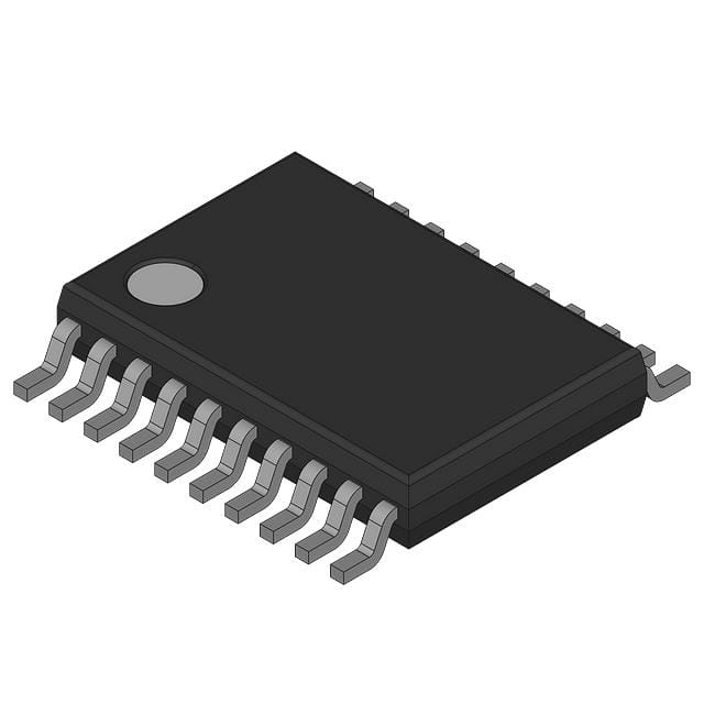
onsemi 74FST3245DT
- Part No.:
- 74FST3245DT
- Manufacturer:
- onsemi
- Package:
- -
- Datasheet:
-
 74FST3245DT.pdf
- Description:
- BUS DRIVER
- Quantity:
- Payment:

- Shipping:

Inventory:34,575
Please send an inquiry. Send us your inquiry, and we will respond immediately.
Product details
Overview
74FST3245DT from ON Semiconductor is an 8-bit CMOS bus switch operating at 4.0–5.5 V, featuring 4 Ω typical on-resistance, ≤0.25 ns max propagation delay, and TTL/CMOS-compatible control inputs. It enables bidirectional signal routing between Port A and Port B when OE is low, serving as a low-noise, zero-ground-bounce interface in high-speed digital backplanes.
For engineers reviewing the 74FST3245DT datasheet, pinout, applications, or equivalent options, key selection criteria include its TSSOP-20 Pb-free package, sub-nanosecond enable/disable timing (tPZH/tPLZ ≤ 6.0 ns), and guaranteed RON ≤ 7 Ω at 4.0 V - critical for maintaining signal integrity in dense PCB layouts.
Technical Context
The 74FST3245DT implements an array of eight independent bilateral analog switches controlled by a single active-low OE input. Each switch exhibits near-zero charge injection and no DC path between ports in high-Z state, eliminating switching transients that cause ground bounce in synchronous bus systems.
Its architecture relies on complementary MOSFET pairs per channel to achieve symmetric conduction and minimal voltage-dependent RON variation. The device operates without internal latches or level-shifting circuitry, making it suitable for direct connection between logic families with shared VCC domains.
Key Specifications
| Parameter | Value and Actual Design Meaning |
|---|---|
| Supply Voltage | 4.0–5.5 V - compatible with standard 5 V TTL/CMOS logic rails without level translation |
| RON (Typ/Max) | 4 Ω / 7 Ω at 4.5 V - ensures <50 mV voltage drop at 64 mA per channel, preserving logic thresholds |
| Propagation Delay | ≤0.25 ns - adds negligible timing skew in parallel data paths, enabling >1 GHz effective switching |
| tPZH / tPLZ | ≤6.0 ns at VCC = 4.0 V - supports fast bus arbitration cycles with predictable enable/disable latency |
| Input Leakage | ≤1.0 μA - prevents unintended biasing in high-impedance test or debug configurations |
| ESD Rating | 2000 V HBM - meets industrial I/O robustness requirements without external protection |
Pinout & Package
TSSOP-20 package (Case 948E), 0.65 mm pitch, Pb-free, 6.4 mm × 4.4 mm footprint, 1.2 mm max height - optimized for automated SMT assembly and thermal dissipation in compact layouts.
| Pin/Terminal | Circuit Role | Design Meaning |
|---|---|---|
| 1, 2, 3, 4, 5, 6, 7, 8 | Port A inputs/outputs (A0–A7) | Bidirectional analog/digital signal terminals; electrically identical to Port B side |
| 11, 12, 13, 14, 15, 16, 17, 19 | Port B inputs/outputs (B0–B7) | Matched impedance and timing to Port A; no directionality enforced internally |
| 9 | GND | Signal reference return for all switch channels and control logic |
| 10 | VCC | Single 4.0–5.5 V supply powering both switch array and OE input buffer |
| 20 | OE | Active-low enable controlling all 8 switches simultaneously; high-Z when logic HIGH |
| NC (Pin 18) | No Connect | Internally unconnected; must remain floating or grounded per layout best practice |
Key Features
| Feature | Design Value |
|---|---|
| Ultra-low RON | 4 Ω typical ensures <30 mV IR drop at 7 mA - preserves noise margins in 5 V logic interfaces |
| Zero propagation delay | No added timing skew beyond RC delay of switch + 50 pF load - maintains setup/hold timing budgets |
| No ground bounce | Eliminates simultaneous switching noise during bus enable transitions - critical for mixed-signal PCBs |
| TTL/CMOS-compatible OE | VIH = 2.0 V, VIL = 0.8 V - directly driven by legacy 5 V microcontrollers without pull-ups |
| Pb-free TSSOP-20 | Inherently RoHS-compliant package with JEDEC-standard footprint - simplifies compliance documentation |
Applications
| High-Speed Backplane Interconnect | Memory Bus Isolation |
|---|---|
|
Use Scenario: Isolating two 8-bit memory banks sharing a common data bus in a real-time controller. IC Role / Device Role / Timing Role: Bidirectional bus switch enabling time-multiplexed access while preventing contention during bank switching. Use Value: Sub-0.25 ns delay and 4 Ω RON maintain signal rise/fall times and reduce inter-symbol interference across 100+ MHz address/data cycles. |
Use Scenario: Enabling hot-plug capability for SRAM modules in industrial PLC I/O carriers. IC Role / Device Role / Timing Role: OE-controlled isolation barrier that disconnects unpowered modules before insertion/removal. Use Value: High-Z state eliminates leakage paths and prevents back-driving of live bus lines - avoids latch-up in powered subsystems. |
| Test Access Multiplexer | Digital Logic Prototyping |
|
Use Scenario: Routing JTAG or boundary-scan signals between multiple ASICs on a production test fixture. IC Role / Device Role / Timing Role: Low-capacitance (5 pF CI/O), low-RON switch minimizing signal attenuation and reflection. Use Value: 5 pF I/O capacitance and 0.25 ns delay preserve TCK edge fidelity up to 50 MHz - ensuring reliable scan chain operation. |
Use Scenario: Reconfiguring signal paths between FPGA I/O banks and peripheral headers on a development board. IC Role / Device Role / Timing Role: Manual or firmware-controlled signal router replacing jumpers or solder bridges. Use Value: Pin-compatible replacement for QS3245/FST3245 allows reuse of existing PCB footprints across design iterations. |
Equivalent & Alternatives
The following parts are listed as comparable options for similar bus switch applications.
| Alternative Part | Technical Difference | Application Difference | Selection Advice |
|---|---|---|---|
| SN74CBT3245APW | RON = 5 Ω typ at 5 V; tPLH = 0.25 ns; same TSSOP-20 pinout but TI-specific marking | Higher ICC quiescent current (10 μA vs. 3 μA); slightly lower ESD rating (1500 V HBM) | Preferred where TI ecosystem support and SPICE model availability are prioritized over lowest standby current |
| MC74VHC3245DT | RON = 10 Ω max at 4.5 V; tPHL = 2.5 ns; higher propagation delay and on-resistance | Designed for wider VCC range (2–5.5 V); less suitable for high-speed 5 V-only buses | Selected when dual-supply flexibility or legacy VHC family compatibility outweighs speed requirements |
Compared with SN74CBT3245APW and MC74VHC3245DT, the 74FST3245DT delivers the lowest RON and fastest enable timing within the 5 V bus switch category, making it optimal for noise-sensitive, high-frequency interconnects where signal fidelity and power efficiency are jointly constrained.
Availability
74FST3245DT is available at Aetrix Electronics and suitable for high-speed backplane interconnect, memory bus isolation, test access multiplexing, and digital logic prototyping requiring stable component supply and full RoHS compliance.
Supply support for 74FST3245DT includes scheduled delivery planning, volume procurement assistance, BOM continuity management, traceable sourcing, and lifecycle availability coordination for OEM customers, industrial embedded developers, connected-device designers, and electronics production programs.
Manufacturer
ON Semiconductor (now onsemi) is a global semiconductor supplier specializing in energy-efficient power, analog, sensor, and logic solutions for automotive, industrial, and cloud infrastructure markets.
The 74FST3245DT belongs to the FST (Fast Switching Transistor) logic family, engineered specifically for ultra-low-noise, high-bandwidth digital signal routing in mission-critical interconnect applications.
FAQ
What is the maximum operating temperature range for the 74FST3245DT?
The 74FST3245DT is rated for continuous operation from −40 °C to +85 °C ambient temperature. This range is validated per JEDEC JESD78 latch-up testing and thermal resistance characterization (θJA = 128 °C/W for TSSOP-20), ensuring reliability in industrial control and telecom environments where ambient temperatures exceed consumer-grade limits.
Does the 74FST3245DT require external pull-up or pull-down resistors on the OE pin?
No, the 74FST3245DT OE input is TTL/CMOS-compatible with VIH = 2.0 V and VIL = 0.8 V, allowing direct connection to microcontroller GPIOs or logic gates without external biasing. Leaving OE floating is prohibited per datasheet Note 5; it must be actively driven HIGH or LOW to avoid undefined switch states.
Can the 74FST3245DT be used with 3.3 V logic systems?
The 74FST3245DT is not characterized for 3.3 V operation: its minimum recommended VCC is 4.0 V, and RON increases significantly below 4.0 V (e.g., 11–20 Ω at 4.0 V per datasheet Table 3). For 3.3 V systems, consider the 74LVC3245 or similar LVC-family devices explicitly rated down to 1.65 V.
Is the 74FST3245DT pin-compatible with the 74FST3245DW in SOIC-20?
Yes - the 74FST3245DT (TSSOP-20) and 74FST3245DW (SOIC-20) share identical pin numbering, signal assignment, and electrical behavior. Both follow the same 20-pin layout shown in Figure 1, enabling direct PCB footprint substitution when upgrading to smaller packages or Pb-free compliance.
What is the significance of "inherently Pb-free" in the 74FST3245DT datasheet?
"Inherently Pb-free" means the TSSOP-20 package (Case 948E) uses lead-free solderable terminations and mold compound without requiring post-manufacturing rework. This satisfies RoHS Directive 2011/65/EU Annex II exemptions and eliminates concerns about Pb diffusion into adjacent components during reflow, unlike some "Pb-free convertible" packages.
74FST3245DT Specifications
- Product attributes
- Attribute value
- Manufacturer:
- onsemi
- Series:
- *
- Package/Case:
- -
- Packaging:
- Bulk
- Product Status:
- Active
- Logic Type:
- -
- Number of Elements:
- -
- Number of Bits per Element:
- -
- Input Type:
- -
- Output Type:
- -
- Current - Output High, Low:
- -
- Voltage - Supply:
- -
- Operating Temperature:
- -
- Grade:
- -
- Qualification:
- -
- Mounting Type:
- -
- Supplier Device Package:
- -
74FST3245DT FAQ
1.How can I place an order for 74FST3245DT through Aetrix?
Please submit a Request for Quotation (RFQ) for 74FST3245DT on Aetrix. Our sales agent will provide a competitive quotation and guide you through the order confirmation once you accept the terms.
2.Are the price and stock information for 74FST3245DT reliable?
The price and inventory of 74FST3245DT are updated periodically and may fluctuate due to market conditions. Stock and pricing data are typically refreshed every 24 hours. Quotation validity for 74FST3245DT is usually 5 days.
3.What payment methods are accepted for 74FST3245DT?
We accept Wire Transfer, PayPal, Credit Card, Western Union, MoneyGram, and Escrow for 74FST3245DT transactions.
Note: Certain payment methods may incur a processing fee.
4.How is shipping managed for 74FST3245DT?
74FST3245DT orders can be shipped via leading logistics carriers, including DHL, UPS, FedEx, TNT, or Registered Mail.
Once your 74FST3245DT order is processed, you will receive an email with the shipment details and tracking number.
Note: Tracking information may take up to 24 hours to appear. Express delivery typically takes 3–5 business days.
5.How can I obtain technical support or documentation for 74FST3245DT?
For technical support, including 74FST3245DT datasheets, pinout diagrams, or application guidance, please contact our engineering support team. They can provide detailed documentation and assistance for your 74FST3245DT requirements.
6.How does Aetrix verify that 74FST3245DT is sourced from the original manufacturer or authorized distributors?
All 74FST3245DT products on Aetrix are procured from qualified distributors and authorized channels. Our dedicated quality assurance team conducts strict verification, including traceability checks and, if necessary, third-party testing. This ensures that 74FST3245DT meets industry standards.
7.What is the process for return or replacement of 74FST3245DT?
All 74FST3245DT units undergo pre-shipment inspection (PSI). If there is an issue with 74FST3245DT, returns or replacements are accepted under the following conditions:
1.Quantity discrepancies, incorrect items, or visible external defects (such as breakage or corrosion), acknowledged by Aetrix.
2.The issue is reported within 90 days of delivery.
3.The 74FST3245DT part is unused and in its original packaging.
Return procedure for 74FST3245DT:
1.Submit a request within 90 days.
2.Obtain a Return Material Authorization (RMA) from Aetrix.
74FST3245DT Tags

-
SN74LVC1G17DBVR
Texas Instruments

-
SN74LVC1G07DCKR
Texas Instruments
-
SN74LVC1G17DCKR
Texas Instruments
-
SN74LVC1G07DBVR
Texas Instruments
-
SN74LVC1G125DCKR
Texas Instruments
-
SN74AHCT1G126DBVR
Texas Instruments
-
SN74LVC1G125DBVR
Texas Instruments
-
SN74AHCT1G125DBVR
Texas Instruments

-
SN74LVC2G17DBVR
Texas Instruments

-
SN74LVC2G07DCKR
Texas Instruments
-
SN74LVC1G34DCKR
Texas Instruments
-
SN74LVC2G17DCKR
Texas Instruments
Tech Hub

Counterfeit components can hide behind convincing markings and passing basic function tests. This engineering reference covers source traceability, external inspection, X-ray, XRF, electrical testing, …

A practical engineering and sourcing framework covering lifecycle verification, lifetime-buy calculations, replacement qualification, supplier checks and counterfeit-risk controls.

TTL and CMOS logic families differ in thresholds, loading, output drive, power and timing. This engineering guide compares 74HC and 74HCT, calculates noise margins and checks 3.3 V/5 V compatibility.

A practical engineering guide to 3.3V and 5V logic compatibility, input thresholds, resistor dividers, translator ICs, MOSFET level shifting, I2C pull-ups, timing limits and power-sequencing risks.

The 74HC595 uses push-pull logic outputs, while the TPIC6B595 uses 50 V open-drain DMOS sinks for higher-power loads. This guide compares timing, current limits, 3.3 V interfacing, load wiring, thermal…

The 74HC595 converts serial data into eight stable parallel outputs. This guide covers pin functions, shift and storage timing, OE and MR behavior, drive-current limits, cascading, voltage compatibilit…

A technical comparison of level-sensitive latches and edge-triggered flip-flops, covering timing windows, setup and hold limits, master–slave operation, time borrowing, race-through, HDL inference and…

A D latch stores one bit while Enable controls when data can pass. This reference covers gate-level operation, truth tables, transparency, setup and hold timing, LE versus OE, common ICs and practical …

An SR latch stores one bit through cross-coupled feedback. This engineering reference covers NOR and NAND implementations, truth tables, forbidden-state recovery, gated operation, switch debouncing, fa…

Latch circuits retain one bit through feedback. This technical reference covers SR and D latches, truth tables, transparency, timing limits, latch-versus-flip-flop behavior, applications and common log…


