
 My Inquiry
 My Account


Nexperia USA Inc. 74HC4040D,652
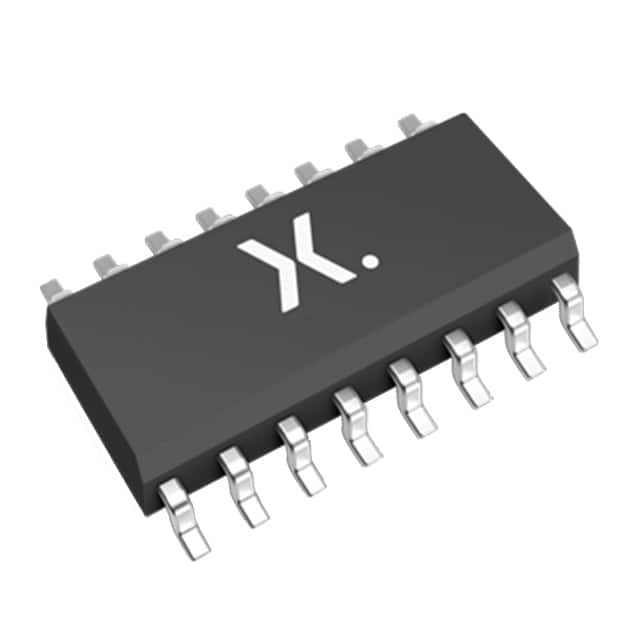
- Part No.:
- 74HC4040D,652
- Manufacturer:
- Nexperia USA Inc.
- Category:
- Counters, Dividers
- Package:
- 16-SOIC (0.154", 3.90mm Width)
- Datasheet:
-
 74HC4040D,652.pdf
- Description:
- IC BINARY COUNTER 12-BIT 16SO
- Quantity:
- Payment:

- Shipping:

Inventory:3,607
Please send an inquiry. Send us your inquiry, and we will respond immediately.
Product details
Overview
74HC4040D,652 from Nexperia is a 12-stage asynchronous binary ripple counter IC with CMOS logic, operating from 2.0 V to 6.0 V supply, featuring a HIGH-to-LOW clock edge-triggered input (CP), active-HIGH asynchronous master reset (MR), and twelve independent Q0–Q11 outputs. It delivers up to 98 MHz maximum clock frequency at VCC = 4.5 V and supports industrial temperature range (−40 °C to +125 °C) in SO16 package. Used in precision frequency division and timing control circuits for industrial instrumentation.
For engineers reviewing the 74HC4040D,652 datasheet, 74HC4040D,652 pinout, 74HC4040D,652 application, or 74HC4040D,652 equivalent, this page provides verified functional identity, validated SO16 pin mapping, confirmed 12-bit ripple counting behavior, real-world timing parameters (e.g., CP→Q0 = 17 ns typ @ 4.5 V), and direct alternatives with documented electrical and application differences.
Technical Context
This device implements a cascaded chain of 12 static toggle flip-flops, where each stage divides its input by two - resulting in Qn output frequency = fCP/2n+1. The counter advances only on the HIGH-to-LOW transition of CP; MR forces all outputs LOW asynchronously, overriding clock state.
No internal synchronization or carry lookahead is present - propagation delay accumulates across stages (Qn→Qn+1 = 10 ns typ @ 4.5 V), making it suitable for non-critical timing but unsuitable for high-speed synchronous systems requiring zero skew or metastability immunity.
Key Specifications
| Parameter | Value and Actual Design Meaning |
|---|---|
| Logic Family | 74HC series CMOS - compatible with 3.3 V and 5 V systems; TTL-level inputs not supported. |
| Counter Stages | 12-bit binary ripple counter - outputs Q0 (LSB) through Q11 (MSB); no intermediate carry-out pin. |
| Max Clock Frequency | 98 MHz @ VCC = 4.5 V, CL = 50 pF - defines highest reliable input pulse rate before timing violations. |
| Propagation Delay (CP→Q0) | 17 ns typical @ VCC = 4.5 V - baseline latency from clock edge to first output toggle. |
| Supply Voltage Range | 2.0 V to 6.0 V - enables operation across battery-powered (3.3 V) and legacy 5 V logic systems. |
| Operating Temperature | −40 °C to +125 °C - qualified for under-hood automotive modules and industrial motor drives. |
| Input Clamping Diodes | Integrated - allows safe interfacing to voltages exceeding VCC when used with current-limiting resistors. |
Pinout & Package
74HC4040D,652 is housed in a plastic small outline package (SO16, SOT109-1) with 16 leads, 3.9 mm body width, and standard 1.27 mm lead pitch. Pin 1 is marked by a notch or dot; pin numbering follows counterclockwise sequence from top-left corner.
| Pin/Terminal | Circuit Role | Design Meaning |
|---|---|---|
| 1 | Q11 | Most significant bit output (211 = 2048× division ratio); open-drain capable only when externally pulled. |
| 2 | Q5 | Mid-range output (25 = 32× division); usable as clock source for sub-systems requiring reduced frequency. |
| 3 | Q4 | 24 = 16× division output; commonly used for LED blink intervals or debounce timing. |
| 4 | Q6 | 26 = 64× division output; matches common microcontroller timer prescaler values. |
| 5 | Q3 | 23 = 8× division output; often routed to enable signals or gated logic blocks. |
| 6 | Q2 | 22 = 4× division output; minimal latency path for fast divide-by-4 functions. |
| 7 | Q1 | 21 = 2× division output; lowest-latency output after Q0; used in dual-edge sampling. |
| 8 | GND | Ground reference for all internal circuitry and I/O; must be low-impedance connection. |
| 9 | Q0 | Least significant bit output (÷2); shortest propagation path; critical for timing-critical feedback loops. |
| 10 | CP | Asynchronous clock input - triggers toggle on HIGH-to-LOW transition only; Schmitt-trigger not included. |
| 11 | MR | Master reset - active HIGH, asynchronous, overrides all clock activity; resets all 12 stages to 0. |
| 12 | Q8 | 28 = 256× division output; aligns with byte-aligned timing windows in serial protocols. |
| 13 | Q7 | 27 = 128× division output; matches standard UART baud rate dividers (e.g., 115.2 kbps). |
| 14 | Q9 | 29 = 512× division output; used in slow-cycle watchdog timeout generation. |
| 15 | Q10 | 210 = 1024× division output; feeds long-interval event counters or power management timers. |
| 16 | VCC | Positive supply voltage - must be decoupled locally with ≥100 nF ceramic capacitor near pin. |
Key Features
| Feature | Design Value |
|---|---|
| Wide supply range | 2.0 V to 6.0 V operation - eliminates need for level shifters when interfacing mixed-voltage subsystems. |
| High noise immunity | Typical VIH = 3.15 V @ VCC = 4.5 V - rejects transient coupling in electrically noisy industrial environments. |
| Latch-up robustness | Exceeds 100 mA per JESD78 Class II Level B - ensures survivability during ESD events or ground bounce. |
| ESD protection | HBM > 2000 V, CDM > 1000 V - reduces risk of field failure in manual handling or unshielded PCB assembly. |
| Thermal performance | Ptot = 500 mW @ Tamb ≤ 110 °C (SO16) - supports continuous operation in enclosed enclosures without forced air. |
Applications
| Frequency Division | Time Delay Generation |
|---|---|
|
Use Scenario: Reducing a 1 MHz system clock to 244 Hz for an LCD segment driver. IC Role / Device Role / Timing Role: Asynchronous divider delivering precise integer division ratios without software overhead. Use Value: Eliminates MCU timer resource usage and guarantees deterministic jitter-free output edges. |
Use Scenario: Creating a 1.024 s delay using Q10 (1024×) from a 1 kHz input clock. IC Role / Device Role / Timing Role: Hardware-based monostable timing element with fixed, repeatable interval. Use Value: Achieves ±1% timing accuracy over −40 °C to +125 °C without calibration or trimming. |
| Control Counter | Industrial Sequencer |
|
Use Scenario: Indexing 12 sequential machine states in a PLC-controlled packaging line. IC Role / Device Role / Timing Role: State register advancing on encoder pulses; MR resets cycle at end-of-batch. Use Value: Provides deterministic, glitch-free state progression immune to CPU interrupt latency. |
Use Scenario: Generating phase-shifted enable signals for three-phase motor drive gate drivers. IC Role / Device Role / Timing Role: Ripple counter feeding combinational logic to produce staggered activation windows. Use Value: Enables hardware-timed commutation without microcontroller real-time scheduling constraints. |
Equivalent & Alternatives
The following parts are listed as comparable options for similar 12-bit asynchronous counter applications.
| Alternative Part | Technical Difference | Application Difference | Selection Advice |
|---|---|---|---|
| 74HCT4040D,652 | TTL-compatible inputs (VIH = 2.0 V min); identical pinout and function; higher input current draw. | Better interoperability with legacy 5 V TTL logic; less suitable for 3.3 V-only systems without level translation. | Select when interfacing directly with 74LS/74ALS families or when guaranteed 2.0 V VIH margin is required. |
| SN74HC4040N | DIP-16 package (SOT38-4); same electrical specs; no thermal pad; lower max ambient rating (−40 °C to +85 °C). | Preferred for prototyping, breadboarding, or legacy through-hole PCBs; not suitable for high-temp reflow or dense layouts. | Choose for lab evaluation or low-volume hand-soldered assemblies where SO16 reflow is impractical. |
Compared with 74HC4040D,652, the 74HCT4040D,652 offers superior TTL interface compatibility at the cost of higher static current, while SN74HC4040N trades industrial temperature range and surface-mount reliability for mechanical ease of use in development environments.
Availability
74HC4040D,652 is available at Aetrix Electronics and suitable for industrial control panels, programmable logic controllers, and embedded timing modules requiring stable component supply across extended temperature ranges and multi-year production cycles.
Supply support for 74HC4040D,652 includes scheduled delivery planning, volume procurement assistance, BOM continuity management, traceable sourcing, and lifecycle availability coordination for OEM customers, industrial embedded developers, connected-device designers, and electronics production programs.
Manufacturer
Nexperia is a global semiconductor expert focused on essential semiconductors, delivering high-performance, reliable components for automotive, industrial, and consumer applications.
The 74HC4040 belongs to Nexperia's industry-standard logic portfolio, designed specifically for robust, low-power digital signal routing and timing control in harsh environments where long-term stability and wide voltage tolerance are mandatory.
FAQ
Can 74HC4040D,652 operate reliably at 3.3 V supply?
Yes - the 74HC4040D,652 is fully specified from 2.0 V to 6.0 V, with VIH = 1.5 V min and VOH = 3.15 V min at VCC = 4.5 V. At 3.3 V, VIH is 1.9 V (typ), ensuring clean recognition of 3.3 V logic HIGH signals. Output swing remains rail-to-rail, supporting direct interface with 3.3 V microcontrollers.
Is there a carry-out or ripple-clock output pin?
No - the 74HC4040D,652 has no dedicated carry-out (RCO) or ripple-clock pin. The highest-order output Q11 serves as de facto carry signal, but its propagation delay includes cumulative stage delays (up to ~225 ns worst-case at 2.0 V). For synchronous carry chaining, external gating of Q11 is required.
What is the minimum pulse width required on CP and MR inputs?
At VCC = 4.5 V, the minimum CP pulse width is 16 ns (HIGH or LOW), and MR pulse width is also 16 ns. These values ensure reliable triggering across the full −40 °C to +125 °C range. Shorter pulses may cause metastability or missed toggles, especially near temperature extremes.
Does this device include Schmitt-trigger inputs for noisy clock sources?
No - the 74HC4040D,652 uses standard CMOS inputs without hysteresis. For clocks with slow rise/fall times or EMI-induced noise, external RC filtering or a dedicated Schmitt-trigger buffer (e.g., 74HC14) is required before CP to prevent multiple counting on a single edge.
74HC4040D,652 Specifications
- Product attributes
- Attribute value
- Manufacturer:
- Nexperia USA Inc.
- Series:
- 74HC
- Package/Case:
- 16-SOIC (0.154", 3.90mm Width)
- Packaging:
- Tube
- Product Status:
- Obsolete
- Logic Type:
- Binary Counter
- Direction:
- Up
- Number of Elements:
- 1
- Number of Bits per Element:
- 12
- Reset:
- Asynchronous
- Timing:
- -
- Count Rate:
- 98 MHz
- Trigger Type:
- Negative Edge
- Voltage - Supply:
- 2 V ~ 6 V
- Operating Temperature:
- -40°C ~ 125°C
- Grade:
- -
- Qualification:
- -
- Mounting Type:
- Surface Mount
- Supplier Device Package:
- 16-SO
74HC4040D,652 FAQ
1.How can I place an order for 74HC4040D,652 through Aetrix?
Please submit a Request for Quotation (RFQ) for 74HC4040D,652 on Aetrix. Our sales agent will provide a competitive quotation and guide you through the order confirmation once you accept the terms.
2.Are the price and stock information for 74HC4040D,652 reliable?
The price and inventory of 74HC4040D,652 are updated periodically and may fluctuate due to market conditions. Stock and pricing data are typically refreshed every 24 hours. Quotation validity for 74HC4040D,652 is usually 5 days.
3.What payment methods are accepted for 74HC4040D,652?
We accept Wire Transfer, PayPal, Credit Card, Western Union, MoneyGram, and Escrow for 74HC4040D,652 transactions.
Note: Certain payment methods may incur a processing fee.
4.How is shipping managed for 74HC4040D,652?
74HC4040D,652 orders can be shipped via leading logistics carriers, including DHL, UPS, FedEx, TNT, or Registered Mail.
Once your 74HC4040D,652 order is processed, you will receive an email with the shipment details and tracking number.
Note: Tracking information may take up to 24 hours to appear. Express delivery typically takes 3–5 business days.
5.How can I obtain technical support or documentation for 74HC4040D,652?
For technical support, including 74HC4040D,652 datasheets, pinout diagrams, or application guidance, please contact our engineering support team. They can provide detailed documentation and assistance for your 74HC4040D,652 requirements.
6.How does Aetrix verify that 74HC4040D,652 is sourced from the original manufacturer or authorized distributors?
All 74HC4040D,652 products on Aetrix are procured from qualified distributors and authorized channels. Our dedicated quality assurance team conducts strict verification, including traceability checks and, if necessary, third-party testing. This ensures that 74HC4040D,652 meets industry standards.
7.What is the process for return or replacement of 74HC4040D,652?
All 74HC4040D,652 units undergo pre-shipment inspection (PSI). If there is an issue with 74HC4040D,652, returns or replacements are accepted under the following conditions:
1.Quantity discrepancies, incorrect items, or visible external defects (such as breakage or corrosion), acknowledged by Aetrix.
2.The issue is reported within 90 days of delivery.
3.The 74HC4040D,652 part is unused and in its original packaging.
Return procedure for 74HC4040D,652:
1.Submit a request within 90 days.
2.Obtain a Return Material Authorization (RMA) from Aetrix.
74HC4040D,652 Tags
-
74HC393BQ,115
Nexperia USA Inc.

-
SN74LV8154PWR
Texas Instruments
-
MC14516BDR2G
onsemi
-
MC14020BDR2G
onsemi

-
MC100EP32DTR2G
onsemi
-
MC100EP016AMNG
onsemi
-
MC100EP016AFAG
onsemi

-
SN74LV163ADR
Texas Instruments

-
SN74LV163APWR
Texas Instruments

-
SN74HC393DR
Texas Instruments
-
SN74HC161DR
Texas Instruments
-
SN74HC163DR
Texas Instruments
Tech Hub

Jumper cables guide covering safe connection order, red and black clamp placement, final ground connection, cable gauge, length, clamp quality, copper vs CCA cables, jump starter comparison and battery…

LDO regulator guide covering low dropout voltage, power dissipation, thermal design, PSRR, output noise, capacitor stability, adjustable LDO circuits, LDO vs buck converter and datasheet selection chec…

Conditional Access Module guide covering CAM meaning, CI/CI+ interface, smart card authorization, DVB security workflow, TV and set-top box compatibility, internal electronics, ESD protection, connecto…

Guide to electronic component obsolescence covering EOL risk, PCN/PDN notices, last-time buy planning, replacement options, form-fit-function validation, counterfeit risk and BOM lifecycle management.

18650 battery guide covering lithium-ion cell basics, 3.6V/3.7V voltage, 4.2V charging, mAh and Wh capacity, protected cells, chargers, BMS, series-parallel packs, holders, welding and sourcing checks.…

Hall effect sensor guide covering working principle, linear and digital sensors, Arduino circuits, current sensing, speed detection, automotive applications, A3144 examples, signal filtering and datash…

Product Change Notification guide for electronic components, covering PCN meaning, PCN vs PDN/EOL, common change types, risk levels, form-fit-function review, engineering validation, BOM control, LTB/L…

A practical guide to blend door actuators, covering HVAC function, symptoms, location, AC and heater issues, reset and calibration, replacement cost, electrical diagnosis, compatibility checks, and rep…

Engineering guide to Raspberry Pi alternatives, covering chip-level differences, Orange Pi, ROCK, Jetson, Banana Pi, NanoPi, Compute Module, Pico, GPIO, camera, HAT compatibility, and replacement risks…

Engineering guide to dynamic load response testing for high-current buck converters, covering load step setup, slew rate, Vcore undershoot, overshoot, recovery time, probe location, output capacitors a…


