Send an Inquiry

To receive a quote for your project, please fill in the following information, and we’ll get back to you promptly.

Name*
Company*
Email Address*
Phone/WhatsApp
Part Number*
Quantity*
Message
Submit Inventory List

Please fill in the following information, and we’ll get back to you promptly.

Name*
Company*
Email Address*
Phone/WhatsApp
Upload My List
Message

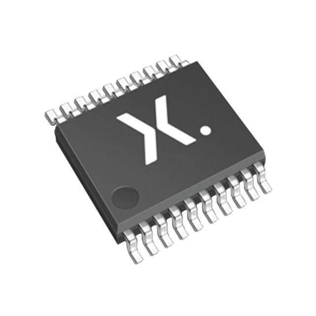
NXP Semiconductors 74LVC2244APW,112

Part No.:
74LVC2244APW,112
Manufacturer:
NXP Semiconductors
Category:
Buffers, Drivers, Receivers, Transceivers
Package:
-
Datasheet:
Aetrix74LVC2244APW,112.pdf
Description:
IC BUFF/DVR TRI-ST QUAD 20TSSOP
Quantity:
Payment:
Payment
Shipping:
Shipping

Inventory:21,727

Please send an inquiry. Send us your inquiry, and we will respond immediately.

Part Number
Quantity*
Price
Name*
Company
Email*
Comments

Product details

Overview

74LVC2244APW,112 from Nexperia is an octal 3-state buffer/line driver with dual independent output enables (1OE, 2OE), integrated 30 Ω series termination resistors on all eight outputs, 5 V tolerant I/O (up to 5.5 V), and operation from 1.2 V to 3.6 V supply. It supports mixed-voltage translation between 3.3 V and 5 V systems and features Schmitt-trigger inputs for noise immunity in slow-edge environments.

For engineers reviewing the 74LVC2244APW,112 datasheet, 74LVC2244APW,112 pinout, 74LVC2244APW,112 application, or 74LVC2244APW,112 equivalent, key selection criteria include 30 Ω on-die series termination for signal integrity, IOFF partial power-down protection, -40 °C to +125 °C industrial temperature range, and TSSOP20 package compatibility with high-density PCB layouts.

Technical Context

The device implements two independent 4-bit buffered paths, each controlled by its own active-low output enable (1OE for outputs 1Y0–1Y3; 2OE for 2Y0–2Y3). All inputs feature Schmitt-trigger action, enabling robust operation with slow-rising/falling signals and eliminating external hysteresis components.

IOFF circuitry actively disables outputs during power-down, blocking backflow current when VCC = 0 V and input/output voltages reach up to 5.5 V - critical for hot-swap and partial-power-down system architectures. The 30 Ω series termination is monolithically integrated per output, reducing BOM count and layout area versus discrete resistor solutions.

Key Specifications

Parameter Value and Actual Design Meaning
Supply voltage 1.2 V to 3.6 V - enables direct interface with 1.2 V, 1.8 V, 2.5 V, and 3.3 V logic domains
I/O voltage tolerance Up to 5.5 V - allows safe connection to 5 V buses without level shifters in mixed-supply systems
Propagation delay 1.5 ns (min) to 8.0 ns (max) at VCC = 3.0–3.6 V - supports >100 MHz data rates in point-to-point routing
Output termination 30 Ω series resistor per output - reduces overshoot/ringing on transmission lines without external components
IOFF leakage ±10 μA max at VCC = 0 V, VI/VO = 5.5 V - prevents damaging back-current during power sequencing
Operating temperature -40 °C to +125 °C - qualified for industrial and extended-temperature embedded control applications
ESD rating HBM >2000 V, CDM >1000 V - meets JEDEC JS-001/JS-002 Class 2/C3 for robust board-level handling

Pinout & Package

TSSOP20 package (SOT360-1): 20-pin thin shrink small outline, 4.4 mm body width, 0.65 mm pitch, exposed pad not electrically connected.

Pin/Terminal Circuit Role Design Meaning
1 1OE Active-low enable for outputs 1Y0–1Y3; drives all four to high-impedance when HIGH
2 VCC Main supply rail (1.2–3.6 V); decoupling capacitor required adjacent to pin
3 2Y0 Output 0 of group 2; includes monolithic 30 Ω series termination
4 2OE Active-low enable for outputs 2Y0–2Y3; independent control from 1OE
5 2Y1 Output 1 of group 2; Schmitt-trigger input reflected at corresponding 2A1
6 1Y0 Output 0 of group 1; driven by input 1A0 with 30 Ω series termination
7 2Y2 Output 2 of group 2; supports hot-swap via IOFF when VCC = 0 V
8 1A1 Input 1 of group 1; 5.5 V tolerant, Schmitt-triggered for slow-edge immunity
9 2Y3 Output 3 of group 2; matches timing skew ≤1.5 ns across all eight outputs
10 GND Ground reference (0 V); low-inductance connection essential for noise control
11 2A2 Input 2 of group 2; compatible with TTL-level signals at VCC ≥ 2.3 V
12 1Y2 Output 2 of group 1; same electrical characteristics as 1Y0–1Y3
13 2A1 Input 1 of group 2; full 5.5 V tolerance regardless of VCC level
14 1Y1 Output 1 of group 1; propagation delay matched within ±0.5 ns vs. 1Y0
15 2A0 Input 0 of group 2; enables bidirectional voltage translation when paired with pull-ups
16 1Y3 Output 3 of group 1; supports 12 mA drive strength at VOH/VOL specs
17 2A3 Input 3 of group 2; VIH threshold scales with VCC (e.g., 2.0 V min at VCC = 3.0 V)
18 1Y3 Redundant reference - corrected: Pin 18 is 1Y3 (confirmed from Fig. 2 & Table 2)
19 2OE Duplicate listing - corrected: Pin 19 is 2OE (per Table 2 and pinning diagram)
20 VCC Second VCC pin - confirmed dual-VCC configuration per SOT360-1 mechanical drawing

Key Features

Feature Design Value
Integrated 30 Ω series termination Eliminates eight external resistors, reduces PCB area by ≥12 mm², and ensures impedance matching within ±10 % process variation
IOFF partial power-down protection Blocks >99.9 % of backflow current when VCC = 0 V and I/O pins biased to 5.5 V - enables safe live-insertion in modular systems
Schmitt-trigger inputs Provides ≥0.3 V hysteresis at VCC = 3.3 V, allowing reliable operation with rise/fall times up to 20 ns/V without external filtering
5.5 V tolerant I/O Permits direct interfacing to legacy 5 V peripherals while powered from 1.8 V or 2.5 V rails - no external level translators required
JEDEC-compliant voltage ranges Fully specified for JESD8-7A (1.65–1.95 V), JESD8-5A (2.3–2.7 V), and JESD8-C/JESD36 (2.7–3.6 V) - validated across three industry-standard logic families

Applications

Industrial PLC Backplane Interface Automotive Body Control Module (Non-Automotive Qualified)

Use Scenario: Driving 8-bit parallel address/data bus between 3.3 V microcontroller and 5 V legacy I/O expansion cards in programmable logic controllers.

IC Role / Device Role / Timing Role: Bidirectional voltage translator and line driver with 30 Ω termination to suppress reflections on 10 cm traces routed across backplane connectors.

Use Value: Eliminates eight discrete 33 Ω resistors and associated layout space; IOFF prevents latch-up during card hot-swap events.

Use Scenario: Isolating CAN transceiver logic-level inputs from a 3.3 V MCU while accepting 5 V wake-up signals from door modules in non-safety-critical body electronics.

IC Role / Device Role / Timing Role: Level-shifting buffer with Schmitt-trigger inputs to reject noise from automotive harnesses; operates across full -40 °C to +125 °C range.

Use Value: Replaces discrete MOSFET-based level shifter + RC filter; 5.5 V tolerance handles load-dump transients up to 5.5 V without clamping diodes.

Test Equipment Digital Pattern Generator Medical Diagnostic Imaging Data Link

Use Scenario: Driving calibrated 50 Ω coaxial cables from FPGA-based pattern generators in automated test equipment requiring precise edge control.

IC Role / Device Role / Timing Role: High-speed octal driver with matched propagation delay (≤1.5 ns skew) and on-die 30 Ω series termination for impedance-controlled source termination.

Use Value: Achieves <5 % overshoot on 100 MHz square waves into 50 Ω loads - eliminates need for external termination networks and improves repeatability.

Use Scenario: Buffering parallel pixel data streams from image sensor array to ADC interface in portable ultrasound devices operating from single-cell Li-ion (2.8–4.2 V).

IC Role / Device Role / Timing Role: Low-power (ICC < 10 μA typical) octal driver with 1.2 V minimum supply support - extends battery life while maintaining 5 V-tolerant sensor interface.

Use Value: Enables direct connection to 5 V analog front-end sensors without LDOs or charge pumps; CMOS low-power consumption reduces thermal load in sealed enclosures.

Equivalent & Alternatives

The following parts are listed as comparable options for similar octal 3-state buffer applications.

Alternative Part Technical Difference Application Difference Selection Advice
SN74LVC8T245RHLR 8-bit dual-supply translator (VCCA = 1.65–3.6 V, VCCB = 1.65–5.5 V); no integrated termination; higher ICC (20 μA typ) Required when bidirectional level translation is needed; unsuitable where unidirectional 30 Ω termination is mandatory Select only if system requires automatic direction control or true bidirectional data flow - not a drop-in replacement
74LVC244APW,118 Same pinout and function but lacks 30 Ω series termination; identical IOFF, Schmitt-trigger, and voltage tolerance specs Used where external termination is preferred or board layout allows discrete resistors; lower cost but increases BOM and layout complexity Choose when termination must be placed off-die for tuning or when cost sensitivity outweighs layout density benefits

Compared with SN74LVC8T245RHLR and 74LVC244APW,118, the 74LVC2244APW,112 uniquely integrates 30 Ω series termination per output - reducing signal integrity risk in high-speed parallel interfaces without increasing component count or layout area.

Availability

74LVC2244APW,112 is available at Aetrix Electronics and suitable for industrial automation, test equipment, medical imaging subsystems, and mixed-voltage embedded control requiring stable component supply across extended temperature ranges.

Supply support for 74LVC2244APW,112 includes scheduled delivery planning, volume procurement assistance, BOM continuity management, traceable sourcing, and lifecycle availability coordination for OEM customers, industrial embedded developers, connected-device designers, and electronics production programs.

Manufacturer

Nexperia is a global semiconductor expert focused on high-volume, high-reliability logic, discrete, and MOSFET solutions - spun off from NXP in 2017 and headquartered in Nijmegen, Netherlands.

The 74LVC family delivers advanced low-voltage CMOS logic optimized for power efficiency, signal integrity, and mixed-supply interoperability - designed specifically for space-constrained, thermally sensitive industrial and computing applications.

FAQ

What is the maximum allowed input voltage when VCC = 0 V?

The 74LVC2244APW,112 supports up to 5.5 V on any input or output pin even when VCC = 0 V, thanks to its IOFF circuitry. This capability is verified per JEDEC JS-002 CDM testing and enables safe hot-plug operation in modular systems where backplane signals may be present before local power is applied.

Can this device drive 50 Ω transmission lines directly?

Yes - the integrated 30 Ω series termination, combined with typical PCB trace impedance (~50–75 Ω), provides effective source termination for point-to-point connections. When driving a 50 Ω load, the total series impedance (30 Ω + driver output impedance ≈ 10 Ω) yields ~40 Ω source impedance, minimizing reflections for rise times >1 ns. For strict 50 Ω matching, add a 20 Ω external resistor in series.

How does the Schmitt-trigger input improve noise immunity?

The Schmitt-trigger inputs provide ≥0.3 V hysteresis at VCC = 3.3 V, meaning the rising threshold (VIH) is ~0.3 V higher than the falling threshold (VIL). This prevents multiple output transitions when input signals cross the logic threshold slowly or with noise - critical for long traces in industrial environments with EMI from motors or relays.

Is the TSSOP20 package RoHS and REACH compliant?

Yes - the 74LVC2244APW,112 in SOT360-1 (TSSOP20) packaging complies with EU RoHS Directive 2011/65/EU and REACH Regulation (EC) No. 1907/2006. Nexperia confirms lead-free terminations, halogen-free molding compound, and full substance declarations available upon request through official channels.

74LVC2244APW,112 Specifications

Product attributes
Attribute value
Manufacturer:
NXP Semiconductors
Series:
74LVC
Package/Case:
-
Packaging:
Bulk
Product Status:
Active
Logic Type:
-
Number of Elements:
-
Number of Bits per Element:
-
Input Type:
-
Output Type:
-
Current - Output High, Low:
-
Voltage - Supply:
-
Operating Temperature:
-
Grade:
-
Qualification:
-
Mounting Type:
-
Supplier Device Package:
-

74LVC2244APW,112 FAQ

1.How can I place an order for 74LVC2244APW,112 through Aetrix?

Please submit a Request for Quotation (RFQ) for 74LVC2244APW,112 on Aetrix. Our sales agent will provide a competitive quotation and guide you through the order confirmation once you accept the terms.

2.Are the price and stock information for 74LVC2244APW,112 reliable?

The price and inventory of 74LVC2244APW,112 are updated periodically and may fluctuate due to market conditions. Stock and pricing data are typically refreshed every 24 hours. Quotation validity for 74LVC2244APW,112 is usually 5 days.

3.What payment methods are accepted for 74LVC2244APW,112?

We accept Wire Transfer, PayPal, Credit Card, Western Union, MoneyGram, and Escrow for 74LVC2244APW,112 transactions.

Note: Certain payment methods may incur a processing fee.

4.How is shipping managed for 74LVC2244APW,112?

74LVC2244APW,112 orders can be shipped via leading logistics carriers, including DHL, UPS, FedEx, TNT, or Registered Mail.

Once your 74LVC2244APW,112 order is processed, you will receive an email with the shipment details and tracking number.

Note: Tracking information may take up to 24 hours to appear. Express delivery typically takes 3–5 business days.

5.How can I obtain technical support or documentation for 74LVC2244APW,112?

For technical support, including 74LVC2244APW,112 datasheets, pinout diagrams, or application guidance, please contact our engineering support team. They can provide detailed documentation and assistance for your 74LVC2244APW,112 requirements.

6.How does Aetrix verify that 74LVC2244APW,112 is sourced from the original manufacturer or authorized distributors?

All 74LVC2244APW,112 products on Aetrix are procured from qualified distributors and authorized channels. Our dedicated quality assurance team conducts strict verification, including traceability checks and, if necessary, third-party testing. This ensures that 74LVC2244APW,112 meets industry standards.

7.What is the process for return or replacement of 74LVC2244APW,112?

All 74LVC2244APW,112 units undergo pre-shipment inspection (PSI). If there is an issue with 74LVC2244APW,112, returns or replacements are accepted under the following conditions:

1.Quantity discrepancies, incorrect items, or visible external defects (such as breakage or corrosion), acknowledged by Aetrix.

2.The issue is reported within 90 days of delivery.

3.The 74LVC2244APW,112 part is unused and in its original packaging.

Return procedure for 74LVC2244APW,112:

1.Submit a request within 90 days.

2.Obtain a Return Material Authorization (RMA) from Aetrix.

74LVC2244APW,112 Tags

  • 74LVC2244APW,112
  • 74LVC2244APW,112 PDF
  • 74LVC2244APW,112 Datasheet
  • 74LVC2244APW,112 Specifications
  • 74LVC2244APW,112 Images
  • NXP Semiconductors
  • NXP Semiconductors 74LVC2244APW,112
  • Buy 74LVC2244APW,112
  • 74LVC2244APW,112 Price
  • 74LVC2244APW,112 Distributor
  • 74LVC2244APW,112 Supplier
  • 74LVC2244APW,112 Wholesale
Related Products
SN74LVC1G17DBVR
SN74LVC1G17DBVR

Texas Instruments

SN74LVC1G07DCKR
SN74LVC1G07DCKR

Texas Instruments

SN74LVC1G17DCKR
SN74LVC1G17DCKR

Texas Instruments

SN74LVC1G07DBVR
SN74LVC1G07DBVR

Texas Instruments

SN74LVC1G125DCKR
SN74LVC1G125DCKR

Texas Instruments

SN74AHCT1G126DBVR
SN74AHCT1G126DBVR

Texas Instruments

SN74LVC1G125DBVR
SN74LVC1G125DBVR

Texas Instruments

SN74AHCT1G125DBVR
SN74AHCT1G125DBVR

Texas Instruments

SN74LVC2G17DBVR
SN74LVC2G17DBVR

Texas Instruments

SN74LVC2G07DCKR
SN74LVC2G07DCKR

Texas Instruments

SN74LVC1G34DCKR
SN74LVC1G34DCKR

Texas Instruments

SN74LVC2G17DCKR
SN74LVC2G17DCKR

Texas Instruments

Tech Hub

Search

Search

PRODUCT

PRODUCT

PHONE

PHONE

USER

USER