
 My Inquiry
 My Account


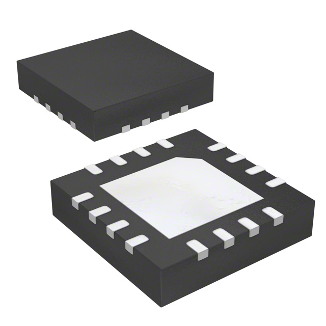
Renesas 844201BKI-45LF
- Part No.:
- 844201BKI-45LF
- Manufacturer:
- Renesas
- Category:
- Specialized ICs
- Package:
- 16-VFQFN Exposed Pad
- Datasheet:
-
 844201BKI-45LF.pdf
- Description:
- IC CLOCK GENERATOR 16VFQFPN
- Quantity:
- Payment:

- Shipping:

Inventory:4,991
Please send an inquiry. Send us your inquiry, and we will respond immediately.
Product details
Overview
844201BKI-45LF from Integrated Device Technology is a PCI Express-compliant crystal-to-LVDS clock generator that synthesizes 100 MHz or 125 MHz reference clocks from a 25 MHz crystal, features a 490–680 MHz VCO range, delivers 0.773 ps RMS phase jitter at 125 MHz (12 kHz–20 MHz), and operates across –40°C to +85°C in PCIe Gen 1/Gen 2 systems.
For engineers reviewing the 844201BKI-45LF datasheet, 844201BKI-45LF pinout, 844201BKI-45LF application, or 844201BKI-45LF equivalent, this page provides verified pin functions, PCIe jitter compliance details, LVDS output design values, crystal interface requirements, and validated alternative clock generators for reference clock subsystems.
Technical Context
The 844201BKI-45LF implements a PLL-based architecture with fixed M = ÷20 and programmable N = ÷4 (default) or ÷5 via FSEL pin, enabling dual-output-frequency selection. Its phase detector drives a wide-range VCO (490–680 MHz), followed by LVDS output drivers compliant with PCI Express Gen 1 peak-to-peak jitter limits (≤13.48 ps) and Gen 2 RMS limits (≤1.25 ps high-band, ≤0.33 ps low-band).
It integrates an internal crystal oscillator interface optimized for 18 pF, 25 MHz parallel-resonant crystals, with on-chip pullup resistors (51 kΩ) on FSEL and crystal pins, and supports overdrive input modes using LVCMOS or LVPECL sources - all while maintaining full 3.3 V supply operation and RoHS-compliant VFQFN packaging.
Key Specifications
| Parameter | Value and Actual Design Meaning |
|---|---|
| Output Frequency | 100 MHz or 125 MHz - selectable via FSEL pin; meets PCIe Gen 1/Gen 2 reference clock requirements. |
| RMS Phase Jitter (125 MHz) | 0.773 ps (12 kHz–20 MHz) - ensures compliance with PCIe Gen 2 tREFCLK_HF_RMS limit of 3.1 ps. |
| VCO Range | 490–680 MHz - enables stable frequency synthesis with integer-N PLL and fixed M/N ratios. |
| Crystal Interface | Optimized for 25 MHz, 18 pF parallel-resonant crystal - requires external 27 pF load capacitors (C1/C2) for ppm accuracy. |
| LVDS Output Drive | Differential voltage (VOD) 247–454 mV, offset voltage (VOS) 1.3–1.63 V - compatible with standard 100 Ω point-to-point termination. |
| Supply Voltage | 3.3 V ±10% - supports industrial temperature range (–40°C to +85°C) with 95 mA typical supply current. |
| Operating Temperature | –40°C to +85°C ambient - qualified for embedded computing, storage, and communications equipment. |
Pinout & Package
844201BKI-45LF is housed in a lead-free 16-pin VFQFN package (3 mm × 3 mm × 0.925 mm body, K suffix), with exposed thermal pad and JEDEC MO-220-compliant outline.
| Pin/Terminal | Circuit Role | Design Meaning |
|---|---|---|
| XTAL_IN / XTAL_OUT (Pins 2,3) | Crystal oscillator interface | Drives and receives feedback from 25 MHz, 18 pF parallel-resonant crystal; internal 51 kΩ pullup on XTAL_IN. |
| FSEL (Pin 4) | Frequency select input | LVTTL/LVCMOS logic level; high = 125 MHz output, low = 100 MHz output; internal 51 kΩ pullup. |
| Q / nQ (Pins 11,12) | Differential LVDS output | Provides 100/125 MHz LVDS clock pair with 247–454 mV differential swing and 1.3–1.63 V common-mode voltage. |
| VDD (Pin 10) | Power supply | 3.3 V ±10% input; powers core PLL, VCO, and LVDS drivers; decoupling required per layout guidelines. |
| GND (Pins 5,16) | Ground reference | Primary power return path; connects to PCB ground plane; critical for jitter performance and EMI control. |
| nc (Pins 1,6–9,13–15) | No-connect | Unbonded die pads; must remain unconnected on PCB to avoid parasitic coupling or reliability risk. |
Key Features
| Feature | Design Value |
|---|---|
| Dual-frequency PCIe reference clock generation | 100 MHz or 125 MHz output from single 25 MHz crystal - eliminates need for multiple oscillators in multi-standard systems. |
| Ultra-low RMS phase jitter | 0.773 ps at 125 MHz (12 kHz–20 MHz) - exceeds PCIe Gen 2 jitter specification by >3× margin, enabling robust SerDes lock. |
| Integrated crystal oscillator interface | Supports 18 pF, 25 MHz parallel-resonant crystals with on-chip gain and bias - reduces BOM count and layout sensitivity. |
| LVDS output compliance | Meets ANSI TIA/EIA-644-A electrical specs - ensures interoperability with standard LVDS receivers without level-shifting. |
| Industrial temperature operation | –40°C to +85°C ambient rating - validated for use in server backplanes, network switches, and storage controllers. |
Applications
| PCI Express Gen 2 Root Complex | Enterprise SSD Controller |
|---|---|
Use Scenario: Provides 125 MHz reference clock to CPU PCIe root complex in dual-CPU server motherboard. IC Role / Device Role / Timing Role: Primary reference clock generator sourcing clean, low-jitter timing to PCIe PHY layer. Use Value: Enables Gen 2 link training and stable 5 Gb/s data rates with measured 1.13 ps tREFCLK_HF_RMS jitter - below 3.1 ps spec limit. | Use Scenario: Supplies 100 MHz reference clock to NVMe SSD controller ASIC in enterprise storage array. IC Role / Device Role / Timing Role: Low-phase-noise clock source for PCIe Gen 3 controller's reference input (via backward-compatible Gen 2 mode). Use Value: Achieves 1.25 ps tREFCLK_HF_RMS jitter at 100 MHz - maintains timing margin for high-throughput NAND flash I/O sequencing. |
| 1U Rack-Mount Network Switch | High-Density FPGA Accelerator Card |
Use Scenario: Generates synchronized 125 MHz clocks for multiple switch fabric ASICs in compact 1U chassis. IC Role / Device Role / Timing Role: Centralized clock distribution node feeding LVDS fanout buffers. Use Value: Delivers <13.48 ps peak-to-peak jitter at 125 MHz - satisfies PCIe Gen 1 common clock architecture requirement for multi-device synchronization. | Use Scenario: Provides 100 MHz reference to Xilinx UltraScale+ FPGA's GTY transceivers in PCIe-based AI accelerator card. IC Role / Device Role / Timing Role: High-stability crystal-derived clock generator for FPGA transceiver reference inputs. Use Value: Maintains 0.33 ps tREFCLK_LF_RMS jitter in 10 kHz–1.5 MHz band - suppresses low-frequency wander affecting long-frame error correction. |
Equivalent & Alternatives
The following parts are listed as comparable options for similar crystal-to-LVDS clock generator applications.
| Alternative Part | Technical Difference | Application Difference | Selection Advice |
|---|---|---|---|
| Si5338A-B-GM | Programmable 4-output clock generator with I²C interface; wider frequency range (0.16–350 MHz); higher RMS jitter (0.95 ps @125 MHz). | Supports multi-frequency, multi-protocol systems (PCIe, SATA, USB); requires firmware configuration and external EEPROM. | Select when flexible output count and protocol agility outweigh lowest-jitter priority. |
| ICS844202BKI-45LF | Pin-compatible variant with identical specs but includes spread-spectrum modulation (±0.25%) enabled by default. | Used where EMI reduction is mandatory (e.g., medical imaging, automotive infotainment); adds ~0.1 ps jitter penalty. | Select only if spread spectrum is required; otherwise 844201BKI-45LF offers lower baseline jitter. |
Compared with Si5338A-B-GM and ICS844202BKI-45LF, the 844201BKI-45LF delivers the lowest measured RMS phase jitter (0.773 ps) and simplest implementation (no programming, no spread-spectrum overhead), making it optimal for fixed-frequency PCIe Gen 1/Gen 2 reference clocking where jitter margin and design simplicity are critical.
Availability
844201BKI-45LF is available at Aetrix Electronics and suitable for PCIe server motherboards, enterprise SSDs, network switches, and FPGA accelerator cards requiring stable component supply, consistent lead times, and long-term lifecycle support.
Supply support for 844201BKI-45LF includes scheduled delivery planning, volume procurement assistance, BOM continuity management, traceable sourcing, and lifecycle availability coordination for OEM customers, industrial embedded developers, connected-device designers, and electronics production programs.
Manufacturer
Integrated Device Technology (IDT), now part of Renesas Electronics, is a fabless semiconductor company specializing in timing, memory interface, RF, and sensor signal conditioning ICs for communications, computing, and industrial markets.
The 844201BKI-45LF belongs to IDT's FemtoClock® family of ultra-low-jitter clock generators, designed specifically for PCI Express reference clocking in high-speed serial interconnect applications where phase noise and jitter directly impact link reliability.
FAQ
What is the primary function of the 844201BKI-45LF in a PCIe system?
The 844201BKI-45LF serves as a crystal-to-LVDS clock generator that produces a low-jitter 100 MHz or 125 MHz reference clock for PCIe Gen 1/Gen 2 physical layers. It accepts a 25 MHz crystal input and uses an internal PLL with fixed M/N dividers to synthesize the output, ensuring compliance with PCIe jitter specifications. The 844201BKI-45LF is not a buffer or fanout device - its core role is precise frequency synthesis from a fundamental crystal source.
Does the 844201BKI-45LF require external configuration or programming?
No, the 844201BKI-45LF is a fixed-function device with no serial interface or non-volatile memory. Frequency selection (100 MHz vs. 125 MHz) is controlled solely by the logic level on the FSEL pin (Pin 4), and all PLL parameters - including M = ÷20 and N = ÷4 or ÷5 - are hardwired. No firmware, EEPROM, or I²C setup is needed, simplifying integration and reducing qualification effort for the 844201BKI-45LF.
What crystal specifications are required for reliable operation of the 844201BKI-45LF?
The 844201BKI-45LF is characterized and guaranteed for use with 25 MHz, 18 pF parallel-resonant crystals having ESR ≤50 Ω and shunt capacitance ≤7 pF. External load capacitors C1 and C2 (27 pF each) are recommended for optimal frequency accuracy. Using crystals outside this specification - such as series-resonant types or those with different load capacitance - may cause start-up failure or frequency drift in the 844201BKI-45LF.
How does the 844201BKI-45LF meet PCIe Gen 2 jitter requirements?
The 844201BKI-45LF meets PCIe Gen 2 jitter requirements by delivering 1.13 ps tREFCLK_HF_RMS (1.5 MHz–Nyquist) and 0.32 ps tREFCLK_LF_RMS (10 kHz–1.5 MHz) at 125 MHz - both well below the 3.1 ps and 3.0 ps limits respectively. These values are measured using the official PCIe Common Clock Architecture transfer functions and validated with a 25 MHz crystal input, confirming full compliance for the 844201BKI-45LF in Gen 2 systems.
Can the 844201BKI-45LF drive multiple LVDS receivers simultaneously?
The 844201BKI-45LF's LVDS outputs (Q/nQ) are designed for point-to-point connections with 100 Ω differential termination. Driving multiple receivers directly is not supported - doing so increases capacitive loading, degrades edge rate (tR/tF = 250–450 ps), and raises jitter. For fanout, a dedicated LVDS buffer (e.g., IDT 8T49N241) must be used downstream of the 844201BKI-45LF to maintain signal integrity and PCIe compliance.
844201BKI-45LF Specifications
- Product attributes
- Attribute value
- Manufacturer:
- Renesas
- Series:
- -
- Package/Case:
- 16-VFQFN Exposed Pad
- Packaging:
- Tube
- Product Status:
- Obsolete
- Programmable:
- Not Verified
- Type:
- Clock Generator
- Applications:
- -
- Mounting Type:
- Surface Mount
- Supplier Device Package:
- 16-VFQFPN (3x3)
- Grade:
- -
- Qualification:
- -
844201BKI-45LF FAQ
1.How can I place an order for 844201BKI-45LF through Aetrix?
Please submit a Request for Quotation (RFQ) for 844201BKI-45LF on Aetrix. Our sales agent will provide a competitive quotation and guide you through the order confirmation once you accept the terms.
2.Are the price and stock information for 844201BKI-45LF reliable?
The price and inventory of 844201BKI-45LF are updated periodically and may fluctuate due to market conditions. Stock and pricing data are typically refreshed every 24 hours. Quotation validity for 844201BKI-45LF is usually 5 days.
3.What payment methods are accepted for 844201BKI-45LF?
We accept Wire Transfer, PayPal, Credit Card, Western Union, MoneyGram, and Escrow for 844201BKI-45LF transactions.
Note: Certain payment methods may incur a processing fee.
4.How is shipping managed for 844201BKI-45LF?
844201BKI-45LF orders can be shipped via leading logistics carriers, including DHL, UPS, FedEx, TNT, or Registered Mail.
Once your 844201BKI-45LF order is processed, you will receive an email with the shipment details and tracking number.
Note: Tracking information may take up to 24 hours to appear. Express delivery typically takes 3–5 business days.
5.How can I obtain technical support or documentation for 844201BKI-45LF?
For technical support, including 844201BKI-45LF datasheets, pinout diagrams, or application guidance, please contact our engineering support team. They can provide detailed documentation and assistance for your 844201BKI-45LF requirements.
6.How does Aetrix verify that 844201BKI-45LF is sourced from the original manufacturer or authorized distributors?
All 844201BKI-45LF products on Aetrix are procured from qualified distributors and authorized channels. Our dedicated quality assurance team conducts strict verification, including traceability checks and, if necessary, third-party testing. This ensures that 844201BKI-45LF meets industry standards.
7.What is the process for return or replacement of 844201BKI-45LF?
All 844201BKI-45LF units undergo pre-shipment inspection (PSI). If there is an issue with 844201BKI-45LF, returns or replacements are accepted under the following conditions:
1.Quantity discrepancies, incorrect items, or visible external defects (such as breakage or corrosion), acknowledged by Aetrix.
2.The issue is reported within 90 days of delivery.
3.The 844201BKI-45LF part is unused and in its original packaging.
Return procedure for 844201BKI-45LF:
1.Submit a request within 90 days.
2.Obtain a Return Material Authorization (RMA) from Aetrix.
844201BKI-45LF Tags

-
CAP200DG-TL
Power Integrations
-
ATSHA204A-MAHDA-T
Microchip Technology

-
ATSHA204A-SSHDA-T
Microchip Technology

-
ATSHA204A-STUCZ-T
Microchip Technology
-
ATECC608B-MAHDA-T
Microchip Technology
-
ATECC608B-MAHCZ-S
Microchip Technology

-
ATECC608B-SSHDA-T
Microchip Technology
-
ATECC608B-MAHDA-S
Microchip Technology
-
ATECC608A-MAHDA-S
Microchip Technology
-
ATECC608B-MAVDA-T
Microchip Technology

-
ATECC608A-SSHDA-T
Microchip Technology
-
ATECC508A-MAHDA-T
Microchip Technology
Tech Hub

TTL and CMOS logic families differ in thresholds, loading, output drive, power and timing. This engineering guide compares 74HC and 74HCT, calculates noise margins and checks 3.3 V/5 V compatibility.

A practical engineering guide to 3.3V and 5V logic compatibility, input thresholds, resistor dividers, translator ICs, MOSFET level shifting, I2C pull-ups, timing limits and power-sequencing risks.

The 74HC595 uses push-pull logic outputs, while the TPIC6B595 uses 50 V open-drain DMOS sinks for higher-power loads. This guide compares timing, current limits, 3.3 V interfacing, load wiring, thermal…

The 74HC595 converts serial data into eight stable parallel outputs. This guide covers pin functions, shift and storage timing, OE and MR behavior, drive-current limits, cascading, voltage compatibilit…

A technical comparison of level-sensitive latches and edge-triggered flip-flops, covering timing windows, setup and hold limits, master–slave operation, time borrowing, race-through, HDL inference and…

A D latch stores one bit while Enable controls when data can pass. This reference covers gate-level operation, truth tables, transparency, setup and hold timing, LE versus OE, common ICs and practical …

An SR latch stores one bit through cross-coupled feedback. This engineering reference covers NOR and NAND implementations, truth tables, forbidden-state recovery, gated operation, switch debouncing, fa…

Latch circuits retain one bit through feedback. This technical reference covers SR and D latches, truth tables, transparency, timing limits, latch-versus-flip-flop behavior, applications and common log…

An engineering guide to LED driver operation, constant-current and constant-voltage outputs, linear and switching topologies, dimming, IC selection, calculations, replacement compatibility, and fault c…

Operational amplifier guide covering op amp basics, feedback, ideal vs real op amps, common configurations, buffer circuits, offset, bias current, gain-bandwidth, slew rate, rail-to-rail limits and sel…


