
 My Inquiry
 My Account


Allegro MicroSystems ATS668LSMTN-T
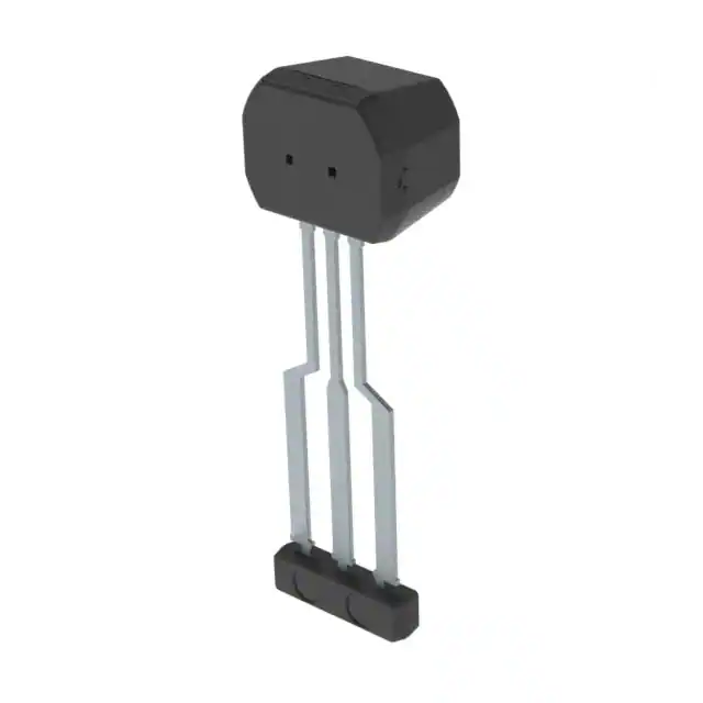
- Part No.:
- ATS668LSMTN-T
- Manufacturer:
- Allegro MicroSystems
- Package:
- 3-SIP
- Datasheet:
-
 ATS668LSMTN-T.pdf
- Description:
- THREE-WIRE DIFFERENTIAL SPEED SE
- Quantity:
- Payment:

- Shipping:

Inventory:30,065
Please send an inquiry. Send us your inquiry, and we will respond immediately.
Product details
Overview
ATS668LSMTN-T from Allegro MicroSystems is a true zero-speed, high-accuracy Hall-effect gear tooth sensor IC optimized for automotive transmission speed sensing. It features integrated EMC protection, adaptive gain/offset compensation, 0–12 kHz operating speed range, ±60 G allowable user-induced offset, and operates across –40 °C to +150 °C ambient temperature in a 3-pin SIP package.
For engineers reviewing the ATS668LSMTN-T datasheet, ATS668LSMTN-T pinout, ATS668LSMTN-T application, or ATS668LSMTN-T equivalent, this device delivers robust digital gear tooth detection with air-gap-independent switching, vibration-immune small-signal lockout, and high-speed startup - critical for transmission control units, differential speed monitoring, and dual-wheel speed sensing systems.
Technical Context
The ATS668LSMTN-T integrates a dual-element Hall IC with on-die AGC and AOA circuitry to dynamically adapt switching thresholds based on peak-detecting DACs, enabling stable operation across variable air gaps (0.5–2.5 mm) and temperature extremes. Its differential magnetic sensing architecture rejects common-mode offsets induced by magnet drift or mechanical misalignment.
It employs a self-calibrating architecture requiring only two rising output edges at power-on for full edge accuracy, supports reverse rotation polarity detection, and includes watchdog logic to recover from magnetic signal loss due to impulse or vibration - all while maintaining undervoltage lockout (4.1–4.55 V) and internal Zener clamping (28 V supply/output).
Key Specifications
| Parameter | Value and Actual Design Meaning |
|---|---|
| Operating Speed Range | 0–12 kHz - enables true zero-speed detection and accurate RPM measurement up to 720 RPM on a 60-tooth gear. |
| Air Gap Range | 0.5–2.5 mm guaranteed operation - accommodates mechanical tolerances without external calibration or tuning. |
| Supply Voltage Range | 4.6–24 V - compatible with 5 V, 12 V, and 24 V automotive battery systems with built-in UVLO and Zener clamp. |
| Output Type | Digital open-collector sink (25 mA max) - directly interfaces with microcontroller GPIO or ECU input stages without level-shifting. |
| Temperature Range | –40 °C to +150 °C ambient - qualified for under-hood transmission and driveline mounting locations. |
| Magnetic Offset Tolerance | ±60 G dynamic cancellation - compensates for assembly-induced field asymmetry and thermal drift in permanent magnet biasing. |
| Power-On Time | ≤2 ms - includes automatic offset adjust completion, enabling fast system wake-up in start-stop applications. |
Pinout & Package
ATS668LSMTN-T is housed in a RoHS-compliant, lead-free 3-pin Single-In-Line (SIP) package with matte-tin leadframe plating, optimized for surface-mount or through-hole mounting in space-constrained transmission housings. Package dimensions: 15.58 mm × 7.65 mm × 5.00 mm (L×W×H), branded face orientation critical for target alignment.
| Pin/Terminal | Circuit Role | Design Meaning |
|---|---|---|
| 1 | VCC | Positive supply input - accepts 4.6–24 V with integrated UVLO and 28 V Zener clamp for load-dump protection. |
| 2 | GND | Ground reference - shared return path for supply and output stage; requires low-impedance connection to minimize noise coupling. |
| 3 | VOUT | Open-collector digital output - sinks up to 25 mA; requires external pull-up resistor (typically 1 kΩ to 5 V or VCC) for logic-level interface. |
Key Features
| Feature | Design Value |
|---|---|
| Integrated EMC Protection | On-package RC network (RSUPPLY = 50 Ω, CSUPPLY = 220 nF) eliminates need for external filtering in ISO 11452-2/4/5-compliant automotive environments. |
| Automatic Gain Control (AGC) | Adjusts internal amplifier gain in real time to maintain consistent signal amplitude across air gaps from 0.5 mm to 3.0 mm - ensures reliable switching without manual gain tuning. |
| Running Mode Lockout | Suppresses output toggling during low-amplitude vibration signals (<60% of nominal Bseq), preventing false counts in harsh driveline environments. |
| True Zero-Speed Operation | Digital output transitions at standstill - enables parking gear detection, neutral confirmation, and static position verification without motion. |
| Reverse Rotation Detection | Output polarity inversion (rising vs. falling edge triggered) identifies direction of gear rotation - supports differential speed and torque estimation algorithms. |
Applications
| Transmission Input Speed Sensing | Driveshaft Differential Speed Monitoring |
|---|---|
|
Use Scenario: Mounted on automatic transmission housing to detect rotational speed of input shaft via 60-tooth gear. IC Role / Device Role / Timing Role: Provides synchronized digital pulse train representing shaft RPM with <2 ms latency and zero-speed capability. Use Value: Enables precise torque converter lock-up control and shift timing - critical for fuel economy and shift smoothness. |
Use Scenario: Paired sensors on left/right driveshafts to monitor speed differential during cornering or traction events. IC Role / Device Role / Timing Role: Delivers phase-aligned, air-gap-insensitive outputs for real-time differential calculation in AWD/4WD ECUs. Use Value: Supports torque vectoring and stability control by detecting <1 RPM speed differences with no calibration drift over temperature. |
| Electric Powertrain Motor Rotor Position | Heavy-Duty Axle Gear Monitoring |
|
Use Scenario: Integrated into e-axle motor housing to sense rotor position via ferrous target ring mounted on motor shaft. IC Role / Device Role / Timing Role: Generates commutation-relevant timing pulses with <4 µs rise/fall time and immunity to EMI from nearby inverters. Use Value: Enables sensor-based FOC (Field-Oriented Control) without resolver or encoder - reducing cost and packaging volume. |
Use Scenario: Installed on commercial vehicle rear axle to monitor gear engagement status and detect broken teeth in multi-stage reduction gears. IC Role / Device Role / Timing Role: Detects missing or deformed teeth via duty cycle deviation (39–56%) and amplitude anomaly rejection. Use Value: Provides predictive maintenance data for fleet telematics - avoids catastrophic axle failure through early fault signature recognition. |
Equivalent & Alternatives
The following parts are listed as comparable options for similar gear tooth sensing applications.
| Alternative Part | Technical Difference | Application Difference | Selection Advice |
|---|---|---|---|
| ATS665LSGTN-T | Single-ended Hall architecture; no integrated AGC; narrower air gap range (0.4–1.8 mm); lower max speed (8 kHz). | Limited to fixed-air-gap, lower-vibration applications such as engine camshaft sensing. | Select when cost sensitivity outweighs air gap flexibility and zero-speed requirement is not mandatory. |
| ATS6858LSHTN-T | Higher-resolution dual-output (A/B quadrature); supports direction and velocity; wider voltage range (3.3–26.5 V); larger 4-pin SIP package. | Designed for steering angle and wheel speed where directional resolution is required. | Choose when quadrature output and enhanced EMC robustness (ISO 11452-2 Level 4) are needed - not a drop-in replacement. |
Compared with ATS668LSMTN-T, the ATS665LSGTN-T lacks adaptive gain and zero-speed capability, limiting use in transmission applications; the ATS6858LSHTN-T adds quadrature functionality but increases PCB footprint and system complexity - making ATS668LSMTN-T optimal for cost-sensitive, single-channel, true zero-speed gear sensing.
Availability
ATS668LSMTN-T is available at Aetrix Electronics and suitable for automotive transmission control, driveline diagnostics, and electric powertrain rotor sensing requiring stable component supply, long-term lifecycle support, and AEC-Q100 Grade 0 qualification.
Supply support for ATS668LSMTN-T includes scheduled delivery planning, volume procurement assistance, BOM continuity management, traceable sourcing, and lifecycle availability coordination for OEM customers, industrial embedded developers, connected-device designers, and electronics production programs.
Manufacturer
Allegro MicroSystems is a U.S.-based designer and manufacturer of high-performance Hall-effect sensors, motor drivers, and power ICs, specializing in automotive and industrial motion control solutions since 1989.
The ATS668LSMTN-T belongs to Allegro's True Zero-Speed Gear Tooth Sensor product line, engineered specifically for robust, maintenance-free speed and position sensing in harsh automotive driveline environments - eliminating reliance on external calibration or analog signal conditioning.
FAQ
What is the maximum air gap supported by the ATS668LSMTN-T while maintaining full specification compliance?
The ATS668LSMTN-T guarantees full specification compliance across an operating air gap range of 0.5 mm to 2.5 mm. Beyond 2.5 mm, switching remains functional up to 3.0 mm but is not guaranteed to meet timing accuracy, duty cycle, or noise immunity specs - verified using Allegro's Reference Target 60-0 under controlled conditions.
Does the ATS668LSMTN-T require external passive components for basic operation?
No, the ATS668LSMTN-T integrates internal RSUPPLY (50 Ω), CSUPPLY (220 nF), ROUT (50 Ω), and COUT (1.8 nF) for EMC filtering and output conditioning. Only an external pull-up resistor on VOUT (e.g., 1 kΩ to 5 V) is required for standard logic interfacing - no additional capacitors, resistors, or TVS diodes are needed for ISO 11452-2/4/5 compliance.
How does the ATS668LSMTN-T handle reverse gear rotation detection?
The ATS668LSMTN-T detects reverse rotation by inverting output polarity: rising edges trigger on leading tooth edges during forward rotation (pin 1 → pin 3), while falling edges trigger on trailing edges during reverse rotation (pin 3 → pin 1). This behavior is inherent to its differential Hall architecture and requires no configuration - confirmed in Figure 7 of the ATS668LSM datasheet.
What is the power-on behavior of the ATS668LSMTN-T, and how many gear teeth are needed before output stabilizes?
At power-on, the ATS668LSMTN-T enters a reset state with VOUT held high (POS), completes internal offset adjustment within ≤2 ms, then begins edge detection. Full output edge accuracy is achieved after two rising output edges - typically within one full gear revolution at speeds below 200 Hz - as specified in the CALI parameter (2–3 edges).
Is the ATS668LSMTN-T qualified for automotive under-hood applications?
Yes, the ATS668LSMTN-T is designed and tested for under-hood use: it operates from –40 °C to +150 °C ambient, withstands reverse supply voltage down to –18 V, includes integrated Zener clamps (28 V on VCC/VOUT), and meets automotive EMC requirements via on-package protection - all documented in its AEC-Q100 stress test report and functional safety documentation.
ATS668LSMTN-T Specifications
- Product attributes
- Attribute value
- Manufacturer:
- Allegro MicroSystems
- Series:
- -
- Package/Case:
- 3-SIP
- Packaging:
- Tape & Reel (TR)
- Product Status:
- Active
- Type:
- Hall Effect
- Output Type:
- Digital
- Actuator Material:
- Magnet
- Termination Style:
- PC Pin
- Frequency:
- 12 kHz
- Voltage - Supply:
- -
- Must Operate:
- -
- Must Release:
- -
- Operating Temperature:
- -40°C ~ 150°C
- Grade:
- -
- Qualification:
- -
ATS668LSMTN-T FAQ
1.How can I place an order for ATS668LSMTN-T through Aetrix?
Please submit a Request for Quotation (RFQ) for ATS668LSMTN-T on Aetrix. Our sales agent will provide a competitive quotation and guide you through the order confirmation once you accept the terms.
2.Are the price and stock information for ATS668LSMTN-T reliable?
The price and inventory of ATS668LSMTN-T are updated periodically and may fluctuate due to market conditions. Stock and pricing data are typically refreshed every 24 hours. Quotation validity for ATS668LSMTN-T is usually 5 days.
3.What payment methods are accepted for ATS668LSMTN-T?
We accept Wire Transfer, PayPal, Credit Card, Western Union, MoneyGram, and Escrow for ATS668LSMTN-T transactions.
Note: Certain payment methods may incur a processing fee.
4.How is shipping managed for ATS668LSMTN-T?
ATS668LSMTN-T orders can be shipped via leading logistics carriers, including DHL, UPS, FedEx, TNT, or Registered Mail.
Once your ATS668LSMTN-T order is processed, you will receive an email with the shipment details and tracking number.
Note: Tracking information may take up to 24 hours to appear. Express delivery typically takes 3–5 business days.
5.How can I obtain technical support or documentation for ATS668LSMTN-T?
For technical support, including ATS668LSMTN-T datasheets, pinout diagrams, or application guidance, please contact our engineering support team. They can provide detailed documentation and assistance for your ATS668LSMTN-T requirements.
6.How does Aetrix verify that ATS668LSMTN-T is sourced from the original manufacturer or authorized distributors?
All ATS668LSMTN-T products on Aetrix are procured from qualified distributors and authorized channels. Our dedicated quality assurance team conducts strict verification, including traceability checks and, if necessary, third-party testing. This ensures that ATS668LSMTN-T meets industry standards.
7.What is the process for return or replacement of ATS668LSMTN-T?
All ATS668LSMTN-T units undergo pre-shipment inspection (PSI). If there is an issue with ATS668LSMTN-T, returns or replacements are accepted under the following conditions:
1.Quantity discrepancies, incorrect items, or visible external defects (such as breakage or corrosion), acknowledged by Aetrix.
2.The issue is reported within 90 days of delivery.
3.The ATS668LSMTN-T part is unused and in its original packaging.
Return procedure for ATS668LSMTN-T:
1.Submit a request within 90 days.
2.Obtain a Return Material Authorization (RMA) from Aetrix.
ATS668LSMTN-T Tags
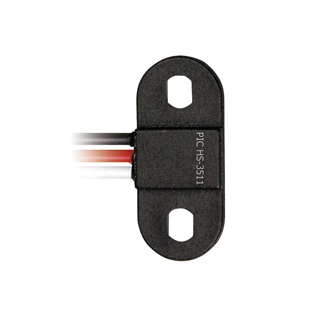
-
HS-3511-02-0300
PIC GmbH
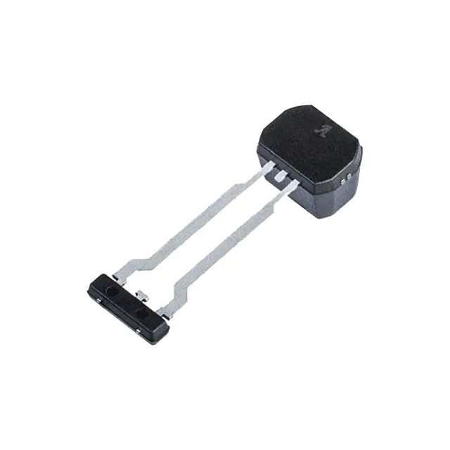
-
ATS19480LSNBTN
Allegro MicroSystems
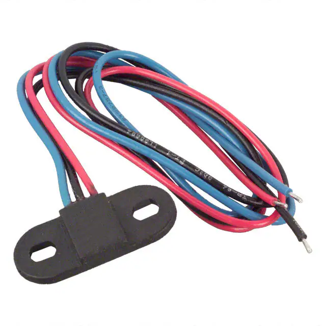
-
55100-2M-02-A
Littelfuse Inc.
-
55100-3H-02-A
Littelfuse Inc.
-
55100-3M-02-A
Littelfuse Inc.
-
55100-3M-03-A
Littelfuse Inc.
-
55100-3H-04-A
Littelfuse Inc.
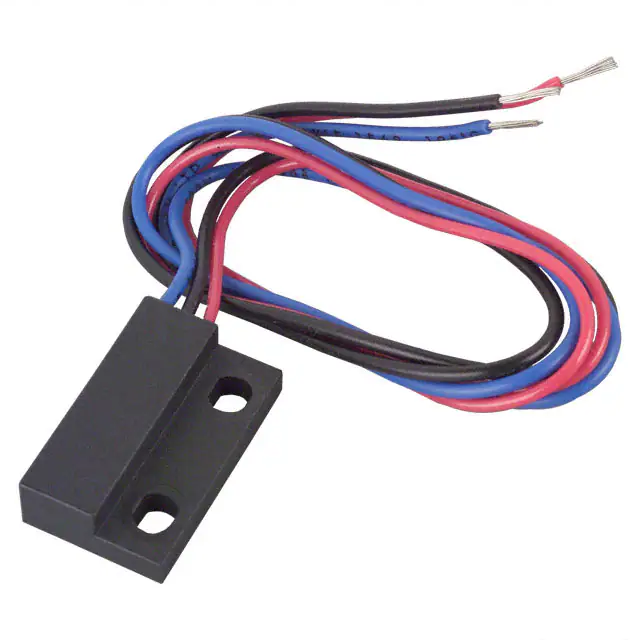
-
55140-3H-02-A
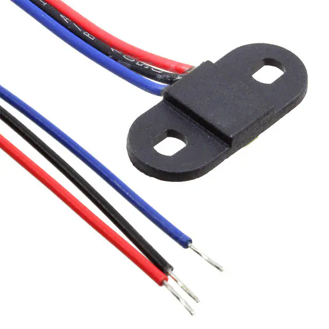
Littelfuse Inc.
-
55100-AP-02-A
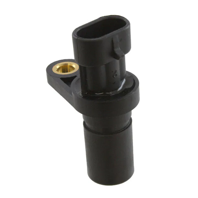
Littelfuse Inc.
-
GS101201
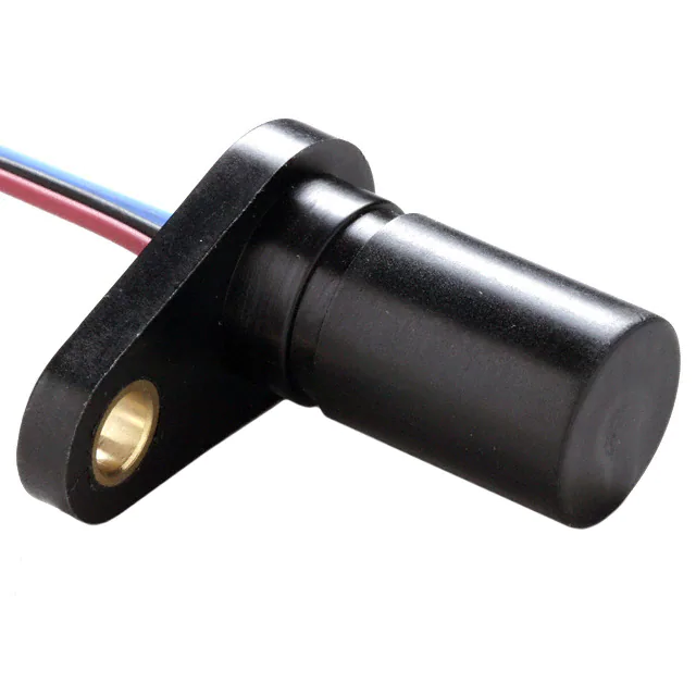
ZF Electronics
-
55505-00-02-A
Littelfuse Inc.
-
GS100701
ZF Electronics
Tech Hub

A practical engineering and sourcing framework covering lifecycle verification, lifetime-buy calculations, replacement qualification, supplier checks and counterfeit-risk controls.

TTL and CMOS logic families differ in thresholds, loading, output drive, power and timing. This engineering guide compares 74HC and 74HCT, calculates noise margins and checks 3.3 V/5 V compatibility.

A practical engineering guide to 3.3V and 5V logic compatibility, input thresholds, resistor dividers, translator ICs, MOSFET level shifting, I2C pull-ups, timing limits and power-sequencing risks.

The 74HC595 uses push-pull logic outputs, while the TPIC6B595 uses 50 V open-drain DMOS sinks for higher-power loads. This guide compares timing, current limits, 3.3 V interfacing, load wiring, thermal…

The 74HC595 converts serial data into eight stable parallel outputs. This guide covers pin functions, shift and storage timing, OE and MR behavior, drive-current limits, cascading, voltage compatibilit…

A technical comparison of level-sensitive latches and edge-triggered flip-flops, covering timing windows, setup and hold limits, master–slave operation, time borrowing, race-through, HDL inference and…

A D latch stores one bit while Enable controls when data can pass. This reference covers gate-level operation, truth tables, transparency, setup and hold timing, LE versus OE, common ICs and practical …

An SR latch stores one bit through cross-coupled feedback. This engineering reference covers NOR and NAND implementations, truth tables, forbidden-state recovery, gated operation, switch debouncing, fa…

Latch circuits retain one bit through feedback. This technical reference covers SR and D latches, truth tables, transparency, timing limits, latch-versus-flip-flop behavior, applications and common log…

An engineering guide to LED driver operation, constant-current and constant-voltage outputs, linear and switching topologies, dimming, IC selection, calculations, replacement compatibility, and fault c…


