
 My Inquiry
 My Account


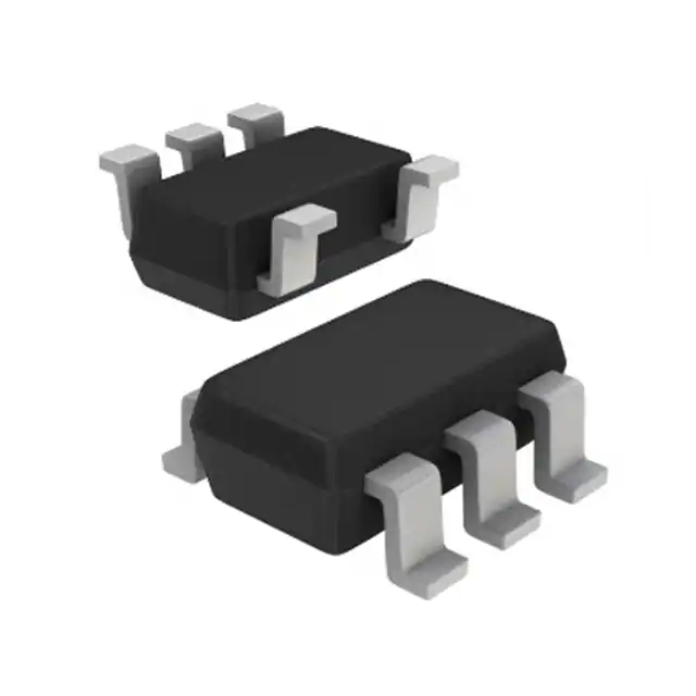
Allegro MicroSystems A1302KLHLT-T
- Part No.:
- A1302KLHLT-T
- Manufacturer:
- Allegro MicroSystems
- Category:
- Linear, Compass (ICs)
- Package:
- SOT-23W
- Datasheet:
-
 A1302KLHLT-T.pdf
- Description:
- SENSOR HALL EFFECT ANALOG SOT23W
- Quantity:
- Payment:

- Shipping:

Inventory:1,964
Please send an inquiry. Send us your inquiry, and we will respond immediately.
Product details
Overview
A1302KLHLT-T from Allegro MicroSystems is a continuous-time, ratiometric, linear Hall-effect sensor IC optimized for accurate voltage output proportional to applied magnetic field. It delivers 1.3 mV/G typical sensitivity, 50% VCC quiescent output, and operates from –40°C to 125°C with 4.5–6.0 V supply. Used in industrial position sensing for rotational and linear motion under extended temperature conditions.
For engineers reviewing the A1302KLHLT-T datasheet, A1302KLHLT-T pinout, A1302KLHLT-T application, or A1302KLHLT-T equivalent, this page provides verified technical context, package-specific pin mapping, real-world use cases, and validated alternative options for high-temperature Hall sensing designs.
Technical Context
The A1302KLHLT-T integrates a Hall element, linear amplifier, and CMOS Class A output stage on a single die, minimizing noise and signal integrity issues common in low-level analog sensing. Its ratiometric architecture ensures both quiescent output voltage (VOUTQ) and magnetic sensitivity scale linearly with supply voltage (VCC).
Internal gain and offset trimming at end-of-line enables ±2.5% linearity and ±3.0% symmetry over temperature. The device achieves 20 kHz bandwidth, 3 μs power-on time, and 150 μVrms wideband output noise with external ≤10 kHz low-pass filtering.
Key Specifications
| Parameter | Value and Actual Design Meaning |
|---|---|
| Sensitivity | 1.3 mV/G typical - enables precise analog field measurement with predictable scaling across supply and temperature |
| Quiescent Output | 50% of VCC - simplifies differential signal conditioning and eliminates need for external reference |
| Supply Range | 4.5–6.0 V - compatible with standard 5 V industrial rails and tolerant of nominal 10% variation |
| Operating Temp | –40°C to +125°C - supports under-hood, motor control, and factory automation environments |
| Output Bandwidth | 20 kHz - sufficient for real-time monitoring of rotating shafts up to ~120,000 RPM (with 1-pole magnet) |
| Power-On Time | 3 μs typical - allows rapid system wake-up and synchronized sampling in low-duty-cycle applications |
| Linearity Error | ±2.5% max - ensures monotonic response across full magnetic range without calibration per unit |
Pinout & Package
Package: 3-pin SOT-23W (LH suffix), surface-mount, lead-free with 100% matte tin plating. Dimensions: 2.90 × 1.60 × 1.00 mm (L × W × H), branded face orientation defined per datasheet drawing.
| Pin/Terminal | Circuit Role | Design Meaning |
|---|---|---|
| VCC (Pin 1) | Positive supply input | Connects to regulated 4.5–6.0 V rail; bypass capacitor required at package pin for noise suppression |
| VOUT (Pin 2) | Analog output | Rail-to-rail, ratiometric voltage proportional to B-field; drives 10 kΩ min load with <5 Ω source impedance |
| GND (Pin 3) | Reference ground | Must be low-impedance return path shared with VCC bypass cap; critical for quiescent accuracy and noise rejection |
Key Features
| Feature | Design Value |
|---|---|
| Ratiometric output | Both VOUTQ and sensitivity track VCC changes - eliminates need for separate voltage reference in systems with varying supply |
| Factory-trimmed offset/gain | End-of-line laser trimming ensures ±3.0% VOUTQ error and ±3.0% sensitivity error over temperature - reduces system-level calibration burden |
| Low-noise analog output | 150 μVrms wideband noise with ≤10 kHz filter - supports sub-gauss resolution in stable mechanical mounting configurations |
| Fast power-on response | 3 μs delay from VCC rise to 95% VOUT - enables microsecond-precision timing in pulsed-field or duty-cycled sensing |
| Robust ESD performance | Qualified to >4 kV HBM - suitable for handling in non-ESD-controlled assembly environments without additional protection |
Applications
| Brushless DC Motor Commutation | Automotive Throttle Position Sensing |
|---|---|
|
Use Scenario: Detect rotor pole position in 3-phase BLDC motors for electronic commutation. IC Role / Device Role / Timing Role: Linear Hall sensor providing analog B-field feedback to MCU ADC for real-time angle estimation. Use Value: 20 kHz bandwidth and 3 μs power-on time enable precise timing alignment with PWM cycles; ±2.5% linearity avoids torque ripple without lookup-table correction. |
Use Scenario: Measure throttle plate angular displacement in gasoline engine air intake systems. IC Role / Device Role / Timing Role: Primary position transducer converting mechanical rotation into ratiometric voltage for ECU interpretation. Use Value: –40°C to +125°C operation ensures reliability across cold starts and under-hood thermal cycling; 1.3 mV/G sensitivity matches typical magnet geometry in compact throttle bodies. |
| Industrial Linear Actuator Feedback | Rotary Encoder Supplement |
|
Use Scenario: Monitor piston extension in hydraulic or pneumatic linear actuators via magnet-on-rod configuration. IC Role / Device Role / Timing Role: Analog field-to-voltage converter feeding PLC analog input module for closed-loop position control. Use Value: Ratiometric output eliminates drift from 5 V rail variation in industrial power supplies; ±3.0% symmetry ensures equal positive/negative field response for bidirectional stroke measurement. |
Use Scenario: Augment optical rotary encoder with redundant magnetic sensing for fault-tolerant motor feedback. IC Role / Device Role / Timing Role: Secondary analog position channel providing independent verification of absolute angle during startup or dust exposure. Use Value: 150 μVrms noise floor enables detection of <0.5 G field shifts - sufficient to resolve 0.1° increments with appropriate magnet design and shielding. |
Equivalent & Alternatives
The following parts are listed as comparable options for similar linear Hall-effect sensor applications.
| Alternative Part | Technical Difference | Application Difference | Selection Advice |
|---|---|---|---|
| ALLEGRO A1324LLHLT-T | Higher sensitivity (5.0 mV/G), same LH package and –40°C to 125°C rating, but lower bandwidth (10 kHz) | Better for low-field or low-speed applications; unsuitable for >60,000 RPM rotor sensing due to bandwidth limit | Select A1324LLHLT-T when field strength is weak (<300 G) and speed is below 10 kRPM; retain A1302KLHLT-T for higher-speed, moderate-field use. |
| INFINEON TLE493DW2B6A0HTSA1 | Digital I²C output, 3-axis, integrated ADC, 12-bit resolution; no analog output or ratiometric behavior | Requires MCU with I²C interface and firmware for data parsing; eliminates analog signal chain but adds protocol overhead | Choose TLE493DW2B6A0HTSA1 for multi-axis sensing or digital bus integration; A1302KLHLT-T remains optimal for simple, low-latency analog feedback loops. |
Compared with A1324LLHLT-T and TLE493DW2B6A0HTSA1, the A1302KLHLT-T offers the best balance of analog simplicity, speed, and high-temperature stability for single-axis field-to-voltage conversion - especially where deterministic latency and minimal external components are critical.
Availability
A1302KLHLT-T is available at Aetrix Electronics and suitable for industrial motor control, automotive throttle systems, and hydraulic actuator feedback requiring stable component supply across extended temperature ranges.
Supply support for A1302KLHLT-T includes scheduled delivery planning, volume procurement assistance, BOM continuity management, traceable sourcing, and lifecycle availability coordination for OEM customers, industrial embedded developers, connected-device designers, and electronics production programs.
Manufacturer
Allegro MicroSystems is a U.S.-based semiconductor company specializing in magnetic sensing and power ICs, headquartered in Worcester, Massachusetts.
The A130x family was designed specifically for high-reliability, analog-output Hall sensing in harsh industrial and automotive environments - emphasizing ratiometric stability, temperature robustness, and factory-trimmed accuracy.
FAQ
What is the operating temperature range for the A1302KLHLT-T?
The A1302KLHLT-T is rated for operation from –40°C to +125°C ambient temperature. This K-grade qualification makes it suitable for under-hood automotive applications, industrial motor drives, and factory automation equipment where thermal extremes are common. The device maintains specified sensitivity (0.85–1.75 mV/G) and quiescent output (2.2–2.8 V at 5 V supply) across this full range.
Does the A1302KLHLT-T require an external bypass capacitor?
Yes, the A1302KLHLT-T requires a ceramic bypass capacitor (typically 0.1 µF X7R) placed as close as possible between VCC (Pin 1) and GND (Pin 3). This is essential to suppress high-frequency noise coupling into the analog signal path and ensure stable quiescent output voltage and low-noise performance. Omission results in increased output ripple and degraded linearity.
How does the ratiometric behavior of the A1302KLHLT-T affect system design?
The A1302KLHLT-T's ratiometric output means both its quiescent voltage and magnetic sensitivity scale directly with VCC. This allows the same ADC reference used for VCC measurement to serve as the reference for digitizing VOUT, eliminating ratio-metric errors caused by supply variation. In practice, this simplifies calibration and improves long-term stability without requiring precision voltage references.
Can the A1302KLHLT-T be used in a 3.3 V system?
No - the A1302KLHLT-T has a minimum supply voltage of 4.5 V and absolute maximum of 8 V. It is not functional or characterized below 4.5 V. For 3.3 V systems, consider Allegro's A1308 or A132x families, which support lower supply rails. Using A1302KLHLT-T at 3.3 V will result in undefined output behavior and potential failure to power up.
What is the meaning of the 'KLHLT-T' suffix in A1302KLHLT-T?
In A1302KLHLT-T, 'K' denotes the –40°C to +125°C temperature grade, 'LH' specifies the 3-pin SOT-23W surface-mount package, 'LT' indicates tape-and-reel packaging (7-inch reel, 3000 units), and 'T' confirms lead-free construction with 100% matte tin plating. This full suffix uniquely identifies the high-temp, SMT, RoHS-compliant variant of the A1302 sensor.
A1302KLHLT-T Specifications
- Product attributes
- Attribute value
- Manufacturer:
- Allegro MicroSystems
- Series:
- -
- Package/Case:
- SOT-23W
- Packaging:
- Tape & Reel (TR)
- Product Status:
- Obsolete
- Technology:
- Hall Effect
- Axis:
- Single
- Output Type:
- Analog Voltage
- Sensing Range:
- -
- Voltage - Supply:
- 4.5V ~ 6V
- Current - Supply (Max):
- 11mA
- Current - Output (Max):
- 10mA
- Resolution:
- -
- Bandwidth:
- 20kHz
- Operating Temperature:
- -40°C ~ 125°C
- Grade:
- -
- Qualification:
- -
- Features:
- -
- Supplier Device Package:
- SOT-23W
- Mounting Type:
- Surface Mount
A1302KLHLT-T FAQ
1.How can I place an order for A1302KLHLT-T through Aetrix?
Please submit a Request for Quotation (RFQ) for A1302KLHLT-T on Aetrix. Our sales agent will provide a competitive quotation and guide you through the order confirmation once you accept the terms.
2.Are the price and stock information for A1302KLHLT-T reliable?
The price and inventory of A1302KLHLT-T are updated periodically and may fluctuate due to market conditions. Stock and pricing data are typically refreshed every 24 hours. Quotation validity for A1302KLHLT-T is usually 5 days.
3.What payment methods are accepted for A1302KLHLT-T?
We accept Wire Transfer, PayPal, Credit Card, Western Union, MoneyGram, and Escrow for A1302KLHLT-T transactions.
Note: Certain payment methods may incur a processing fee.
4.How is shipping managed for A1302KLHLT-T?
A1302KLHLT-T orders can be shipped via leading logistics carriers, including DHL, UPS, FedEx, TNT, or Registered Mail.
Once your A1302KLHLT-T order is processed, you will receive an email with the shipment details and tracking number.
Note: Tracking information may take up to 24 hours to appear. Express delivery typically takes 3–5 business days.
5.How can I obtain technical support or documentation for A1302KLHLT-T?
For technical support, including A1302KLHLT-T datasheets, pinout diagrams, or application guidance, please contact our engineering support team. They can provide detailed documentation and assistance for your A1302KLHLT-T requirements.
6.How does Aetrix verify that A1302KLHLT-T is sourced from the original manufacturer or authorized distributors?
All A1302KLHLT-T products on Aetrix are procured from qualified distributors and authorized channels. Our dedicated quality assurance team conducts strict verification, including traceability checks and, if necessary, third-party testing. This ensures that A1302KLHLT-T meets industry standards.
7.What is the process for return or replacement of A1302KLHLT-T?
All A1302KLHLT-T units undergo pre-shipment inspection (PSI). If there is an issue with A1302KLHLT-T, returns or replacements are accepted under the following conditions:
1.Quantity discrepancies, incorrect items, or visible external defects (such as breakage or corrosion), acknowledged by Aetrix.
2.The issue is reported within 90 days of delivery.
3.The A1302KLHLT-T part is unused and in its original packaging.
Return procedure for A1302KLHLT-T:
1.Submit a request within 90 days.
2.Obtain a Return Material Authorization (RMA) from Aetrix.
A1302KLHLT-T Tags
-
DRV5053VAQDBZR
Texas Instruments
-
MMC5603NJ
Memsic Inc.

-
DRV5055A1QDBZR
Texas Instruments
-
MLX90392ELQ-AAA-011-RE
Melexis Technologies NV

-
CT100LW-HS6
Allegro MicroSystems
-
DRV5056A1ELPGMQ1
Texas Instruments
-
A1304ELHLX-T
Allegro MicroSystems
-
MMC5633NJL
Memsic Inc.
-
A1308KUA-2-T
Allegro MicroSystems
-
A1308KUA-1-T
Allegro MicroSystems
-
SI7210-B-04-IVR
Silicon Labs
-
A1308LLHLT-2-T
Allegro MicroSystems
Tech Hub

A practical engineering and sourcing framework covering lifecycle verification, lifetime-buy calculations, replacement qualification, supplier checks and counterfeit-risk controls.

TTL and CMOS logic families differ in thresholds, loading, output drive, power and timing. This engineering guide compares 74HC and 74HCT, calculates noise margins and checks 3.3 V/5 V compatibility.

A practical engineering guide to 3.3V and 5V logic compatibility, input thresholds, resistor dividers, translator ICs, MOSFET level shifting, I2C pull-ups, timing limits and power-sequencing risks.

The 74HC595 uses push-pull logic outputs, while the TPIC6B595 uses 50 V open-drain DMOS sinks for higher-power loads. This guide compares timing, current limits, 3.3 V interfacing, load wiring, thermal…

The 74HC595 converts serial data into eight stable parallel outputs. This guide covers pin functions, shift and storage timing, OE and MR behavior, drive-current limits, cascading, voltage compatibilit…

A technical comparison of level-sensitive latches and edge-triggered flip-flops, covering timing windows, setup and hold limits, master–slave operation, time borrowing, race-through, HDL inference and…

A D latch stores one bit while Enable controls when data can pass. This reference covers gate-level operation, truth tables, transparency, setup and hold timing, LE versus OE, common ICs and practical …

An SR latch stores one bit through cross-coupled feedback. This engineering reference covers NOR and NAND implementations, truth tables, forbidden-state recovery, gated operation, switch debouncing, fa…

Latch circuits retain one bit through feedback. This technical reference covers SR and D latches, truth tables, transparency, timing limits, latch-versus-flip-flop behavior, applications and common log…

An engineering guide to LED driver operation, constant-current and constant-voltage outputs, linear and switching topologies, dimming, IC selection, calculations, replacement compatibility, and fault c…


