
 My Inquiry
 My Account


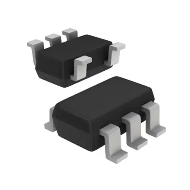
Allegro MicroSystems A1309LLHLT-RP9-T
- Part No.:
- A1309LLHLT-RP9-T
- Manufacturer:
- Allegro MicroSystems
- Category:
- Linear, Compass (ICs)
- Package:
- SOT-23W
- Datasheet:
-
 A1309LLHLT-RP9-T.pdf
- Description:
- SENSOR HALL EFFECT ANALOG SOT23W
- Quantity:
- Payment:

- Shipping:

Inventory:1,371
Please send an inquiry. Send us your inquiry, and we will respond immediately.
Product details
Overview
A1309LLHLT-RP9-T from Allegro MicroSystems is a reverse-polarity, ratiometric linear Hall-effect sensor IC in a 3-pin SOT-23W package, delivering –9 mV/G sensitivity, ±1.5% linearity error, and quiescent output voltage of 2.5 V at 5 V supply. It operates from –40°C to 150°C with AEC-Q100 qualification, and features dynamic offset cancellation, high-speed chopping (400 kHz), and output clamps for automotive throttle position and brake pedal sensing.
For engineers reviewing the A1309LLHLT-RP9-T datasheet, A1309LLHLT-RP9-T pinout, A1309LLHLT-RP9-T application, or A1309LLHLT-RP9-T equivalent, this page delivers verified electrical specs, thermal performance data, real-world use cases in high-temp automotive subsystems, and two validated alternative parts with documented functional and packaging differences.
Technical Context
The A1309LLHLT-RP9-T integrates a BiCMOS monolithic circuit with a Hall element, temperature-compensating circuitry, high-gain amplifier, and proprietary dynamic offset cancellation. Its 400 kHz chopping frequency minimizes QVO drift across temperature, while end-of-line programming sets both sensitivity and QVO temperature coefficients for L-range (–40°C to 150°C) operation.
This device implements ratiometric analog output scaling with VCC, where VOUT(Q) = 50% × VCC, and output clamps (VCLPHIGH = 4.5 V, VCLPLOW = 0.55 V at 5 V) enable short-circuit diagnostics. Undervoltage lockout (UVLO) activates at 2.5 V (off) and 3 V (on), ensuring robust power sequencing in engine control units.
Key Specifications
| Parameter | Value and Actual Design Meaning |
|---|---|
| Sensitivity | –9 mV/G: negative polarity output enables direct detection of north-pole magnetic fields without external inversion. |
| Quiescent Voltage Output | 2.5 V at 5 V supply: precisely centered ratiometric baseline simplifies ADC reference alignment in microcontroller interfaces. |
| Operating Temperature Range | –40°C to 150°C: qualified for under-hood automotive applications including transmission sensors and turbocharger position feedback. |
| Internal Bandwidth | 20 kHz: supports fast-response motion sensing in active suspension and electronic power steering systems. |
| Linearity Error | ±1.5%: ensures sub-degree angular accuracy in rotary position sensing for motor commutation and pedal angle measurement. |
| Supply Current | 9 mA typical: enables low-power operation in always-on vehicle subsystems without excessive thermal load. |
| Output Clamp Voltages | VCLPHIGH = 4.5 V, VCLPLOW = 0.55 V at 5 V: provides fault-detectable saturation boundaries for diagnostic compliance in ISO 26262 ASIL-B designs. |
Pinout & Package
Package: 3-pin SOT-23W (2 mm × 3 mm × 1 mm), surface-mount, lead-free with 100% matte-tin plating, thermal resistance RθJA = 110°C/W on 2-layer PCB.
| Pin/Terminal | Circuit Role | Design Meaning |
|---|---|---|
| VCC | Power input | 5 V nominal supply; requires 0.1 µF bypass capacitor to GND for noise suppression and UVLO stability. |
| VOUT | Analog output | Ratiometric voltage proportional to magnetic field; clamped between 0.55 V and 4.5 V for fault indication. |
| GND | Ground reference | Low-impedance return path; must be connected directly to system ground plane to maintain EMC immunity. |
Key Features
| Feature | Design Value |
|---|---|
| Dynamic offset cancellation | Eliminates thermal and mechanical stress-induced drift, enabling precise recoverability after temperature cycling from –40°C to 150°C. |
| Programmed sensitivity TC | 0.12%/°C typical: factory-set coefficient maintains ±9 mV/G accuracy across full operating range without external calibration. |
| High-speed chopping | 400 kHz modulation: reduces QVO drift to ≤ ±10 mV over temperature, critical for zero-point stability in brake pedal sensors. |
| AEC-Q100 qualified | Grade 0 (–40°C to +150°C): certified for safety-critical automotive applications including powertrain and chassis control modules. |
| Output voltage clamps | Provides inherent short-circuit detection: VOUT forced to clamp levels indicates wiring faults during ECU self-test sequences. |
Applications
| Throttle Position Sensing | Brake Pedal Position Sensing |
|---|---|
Use Scenario: Measures angular displacement of accelerator pedal linkage via rotating magnet mounted on shaft. IC Role / Device Role / Timing Role: Linear Hall-effect sensor providing analog voltage proportional to pedal angle, sampled by MCU ADC at ≥1 kHz. Use Value: ±1.5% linearity and –40°C to 150°C operation ensure accurate torque demand mapping across all ambient conditions and engine bay temperatures. | Use Scenario: Detects linear travel of brake master cylinder pushrod using axial magnet assembly. IC Role / Device Role / Timing Role: Reverse-polarity output (–9 mV/G) directly interfaces with fail-safe dual-redundant brake control ECUs without signal inversion hardware. Use Value: Output clamps (0.55 V / 4.5 V) enable real-time short-circuit diagnostics during ABS activation, meeting ISO 26262 diagnostic coverage requirements. |
| Transmission Gear Selector | Turbocharger Vane Position |
Use Scenario: Monitors rotational position of PRNDL lever in automatic transmission shift-by-wire systems. IC Role / Device Role / Timing Role: High-bandwidth (20 kHz) analog sensor feeding position data to transmission control module for gear engagement timing. Use Value: 9 mA supply current and 50 µs power-on time support rapid wake-up from sleep mode during gear shift events. | Use Scenario: Tracks angular position of variable geometry turbocharger (VGT) vanes exposed to exhaust gas heat. IC Role / Device Role / Timing Role: Temperature-stable Hall sensor mounted near hot-side actuator, reporting vane angle to engine ECU for boost pressure regulation. Use Value: 150°C max ambient rating and < ±10 mV QVO drift over temperature ensure reliable closed-loop control despite thermal cycling. |
Equivalent & Alternatives
The following parts are listed as comparable options for similar linear Hall-effect sensor applications.
| Alternative Part | Technical Difference | Application Difference | Selection Advice |
|---|---|---|---|
| A1309LLHLX-9-T | Same SOT-23W package and 150°C rating, but forward-polarity (+9 mV/G) output. | Requires external signal inversion or MCU software sign-flip for north-pole dominant magnetic configurations. | Select when magnetic orientation allows positive-field sensing and board layout cannot accommodate polarity reversal. |
| A1308LLHLX-9-T | Discontinued part; identical sensitivity and package but rated only to 125°C ambient. | Not suitable for under-hood locations exceeding 125°C, such as near turbochargers or exhaust manifolds. | Acceptable only for cabin or chassis-mounted applications with verified thermal derating below 125°C. |
Compared with A1309LLHLX-9-T, the A1309LLHLT-RP9-T eliminates need for external polarity inversion in north-pole sensing; compared with A1308LLHLX-9-T, it extends operational reliability to 150°C environments critical for modern powertrain systems.
Availability
A1309LLHLT-RP9-T is available at Aetrix Electronics and suitable for automotive throttle position sensing, brake pedal monitoring, transmission gear selection, and turbocharger vane control requiring stable component supply across extended temperature ranges and AEC-Q100-compliant sourcing.
Supply support for A1309LLHLT-RP9-T includes scheduled delivery planning, volume procurement assistance, BOM continuity management, traceable sourcing, and lifecycle availability coordination for OEM customers, industrial embedded developers, connected-device designers, and electronics production programs.
Manufacturer
Allegro MicroSystems is a U.S.-based designer and manufacturer of high-performance magnetic sensing and power ICs, specializing in automotive-grade semiconductor solutions since 1989.
The A1309 series belongs to Allegro's linear Hall-effect sensor product line, engineered specifically for high-accuracy, high-temperature position and displacement sensing in safety-critical automotive powertrain and chassis systems.
FAQ
What is the polarity configuration of the A1309LLHLT-RP9-T?
The A1309LLHLT-RP9-T features reverse polarity output with –9 mV/G sensitivity, meaning its output voltage decreases in response to increasing south-pole magnetic flux and increases for north-pole flux. This polarity is factory-programmed and fixed; the "RP9" suffix explicitly denotes reverse-polarity 9 mV/G calibration. The A1309LLHLT-RP9-T does not support polarity reconfiguration in-circuit.
Does the A1309LLHLT-RP9-T require an external bypass capacitor?
Yes, the A1309LLHLT-RP9-T requires a 0.1 µF ceramic bypass capacitor between VCC and GND, placed as close as possible to the device pins. This capacitor stabilizes the internal regulator, suppresses high-frequency noise from the 400 kHz chopper clock, and ensures proper undervoltage lockout (UVLO) behavior. Omitting it risks erratic output, increased noise, and failure to power up reliably - especially in electrically noisy automotive environments where the A1309LLHLT-RP9-T is commonly deployed.
How does the A1309LLHLT-RP9-T achieve ±1.5% linearity over temperature?
The A1309LLHLT-RP9-T achieves ±1.5% linearity through factory end-of-line optimization of sensitivity and quiescent voltage output (QVO), combined with programmed temperature coefficients for both parameters. Its BiCMOS architecture integrates dynamic offset cancellation and high-speed chopping (400 kHz) to suppress second-order thermal drift. These techniques are validated across –40°C to 150°C per the A1309LLHLT-RP9-T datasheet's LinERR specification, ensuring consistent performance without user calibration.
Can the A1309LLHLT-RP9-T be used in ASIL-B compliant systems?
Yes, the A1309LLHLT-RP9-T supports ASIL-B compliance when integrated into properly architected systems. It is AEC-Q100 Grade 0 qualified (–40°C to +150°C), features built-in diagnostics including output voltage clamps for short-circuit detection, undervoltage lockout with hysteresis, and precise recoverability after temperature cycling - all documented in the A1309LLHLT-RP9-T datasheet. System-level ASIL-B compliance requires additional design measures like redundant sensing paths or watchdog supervision, but the A1309LLHLT-RP9-T provides foundational hardware-level safety mechanisms.
What is the maximum allowable output load capacitance for the A1309LLHLT-RP9-T?
The A1309LLHLT-RP9-T specifies a maximum output load capacitance (CL) of 10 nF, as defined in its Electrical Characteristics table. Exceeding this value may cause instability, overshoot, or delayed settling - particularly during magnetic step transitions where the Delay to Clamp (tCLP) parameter (30 µs typical) assumes CL ≤ 10 nF. For longer cable runs or higher-capacitance PCB traces, a series resistor (e.g., 10–100 Ω) should be added near the A1309LLHLT-RP9-T output pin to isolate capacitive loading and preserve signal integrity.
A1309LLHLT-RP9-T Specifications
- Product attributes
- Attribute value
- Manufacturer:
- Allegro MicroSystems
- Series:
- -
- Package/Case:
- SOT-23W
- Packaging:
- Tape & Reel (TR)
- Product Status:
- Active
- Technology:
- Hall Effect
- Axis:
- -
- Output Type:
- Analog Voltage
- Sensing Range:
- -
- Voltage - Supply:
- 4.5V ~ 5.5V
- Current - Supply (Max):
- 11.5mA
- Current - Output (Max):
- 2mA
- Resolution:
- -
- Bandwidth:
- -
- Operating Temperature:
- -40°C ~ 150°C
- Grade:
- -
- Qualification:
- -
- Features:
- -
- Supplier Device Package:
- SOT-23W
- Mounting Type:
- Surface Mount
A1309LLHLT-RP9-T FAQ
1.How can I place an order for A1309LLHLT-RP9-T through Aetrix?
Please submit a Request for Quotation (RFQ) for A1309LLHLT-RP9-T on Aetrix. Our sales agent will provide a competitive quotation and guide you through the order confirmation once you accept the terms.
2.Are the price and stock information for A1309LLHLT-RP9-T reliable?
The price and inventory of A1309LLHLT-RP9-T are updated periodically and may fluctuate due to market conditions. Stock and pricing data are typically refreshed every 24 hours. Quotation validity for A1309LLHLT-RP9-T is usually 5 days.
3.What payment methods are accepted for A1309LLHLT-RP9-T?
We accept Wire Transfer, PayPal, Credit Card, Western Union, MoneyGram, and Escrow for A1309LLHLT-RP9-T transactions.
Note: Certain payment methods may incur a processing fee.
4.How is shipping managed for A1309LLHLT-RP9-T?
A1309LLHLT-RP9-T orders can be shipped via leading logistics carriers, including DHL, UPS, FedEx, TNT, or Registered Mail.
Once your A1309LLHLT-RP9-T order is processed, you will receive an email with the shipment details and tracking number.
Note: Tracking information may take up to 24 hours to appear. Express delivery typically takes 3–5 business days.
5.How can I obtain technical support or documentation for A1309LLHLT-RP9-T?
For technical support, including A1309LLHLT-RP9-T datasheets, pinout diagrams, or application guidance, please contact our engineering support team. They can provide detailed documentation and assistance for your A1309LLHLT-RP9-T requirements.
6.How does Aetrix verify that A1309LLHLT-RP9-T is sourced from the original manufacturer or authorized distributors?
All A1309LLHLT-RP9-T products on Aetrix are procured from qualified distributors and authorized channels. Our dedicated quality assurance team conducts strict verification, including traceability checks and, if necessary, third-party testing. This ensures that A1309LLHLT-RP9-T meets industry standards.
7.What is the process for return or replacement of A1309LLHLT-RP9-T?
All A1309LLHLT-RP9-T units undergo pre-shipment inspection (PSI). If there is an issue with A1309LLHLT-RP9-T, returns or replacements are accepted under the following conditions:
1.Quantity discrepancies, incorrect items, or visible external defects (such as breakage or corrosion), acknowledged by Aetrix.
2.The issue is reported within 90 days of delivery.
3.The A1309LLHLT-RP9-T part is unused and in its original packaging.
Return procedure for A1309LLHLT-RP9-T:
1.Submit a request within 90 days.
2.Obtain a Return Material Authorization (RMA) from Aetrix.
A1309LLHLT-RP9-T Tags
-
DRV5053VAQDBZR
Texas Instruments
-
MMC5603NJ
Memsic Inc.

-
DRV5055A1QDBZR
Texas Instruments
-
MLX90392ELQ-AAA-011-RE
Melexis Technologies NV

-
CT100LW-HS6
Allegro MicroSystems
-
DRV5056A1ELPGMQ1
Texas Instruments
-
A1304ELHLX-T
Allegro MicroSystems
-
MMC5633NJL
Memsic Inc.
-
A1308KUA-2-T
Allegro MicroSystems
-
A1308KUA-1-T
Allegro MicroSystems
-
SI7210-B-04-IVR
Silicon Labs
-
A1308LLHLT-2-T
Allegro MicroSystems
Tech Hub

A practical engineering and sourcing framework covering lifecycle verification, lifetime-buy calculations, replacement qualification, supplier checks and counterfeit-risk controls.

TTL and CMOS logic families differ in thresholds, loading, output drive, power and timing. This engineering guide compares 74HC and 74HCT, calculates noise margins and checks 3.3 V/5 V compatibility.

A practical engineering guide to 3.3V and 5V logic compatibility, input thresholds, resistor dividers, translator ICs, MOSFET level shifting, I2C pull-ups, timing limits and power-sequencing risks.

The 74HC595 uses push-pull logic outputs, while the TPIC6B595 uses 50 V open-drain DMOS sinks for higher-power loads. This guide compares timing, current limits, 3.3 V interfacing, load wiring, thermal…

The 74HC595 converts serial data into eight stable parallel outputs. This guide covers pin functions, shift and storage timing, OE and MR behavior, drive-current limits, cascading, voltage compatibilit…

A technical comparison of level-sensitive latches and edge-triggered flip-flops, covering timing windows, setup and hold limits, master–slave operation, time borrowing, race-through, HDL inference and…

A D latch stores one bit while Enable controls when data can pass. This reference covers gate-level operation, truth tables, transparency, setup and hold timing, LE versus OE, common ICs and practical …

An SR latch stores one bit through cross-coupled feedback. This engineering reference covers NOR and NAND implementations, truth tables, forbidden-state recovery, gated operation, switch debouncing, fa…

Latch circuits retain one bit through feedback. This technical reference covers SR and D latches, truth tables, transparency, timing limits, latch-versus-flip-flop behavior, applications and common log…

An engineering guide to LED driver operation, constant-current and constant-voltage outputs, linear and switching topologies, dimming, IC selection, calculations, replacement compatibility, and fault c…


