
 My Inquiry
 My Account


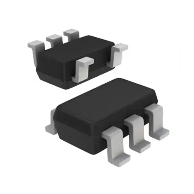
Allegro MicroSystems A1318LLHLX-2-T
- Part No.:
- A1318LLHLX-2-T
- Manufacturer:
- Allegro MicroSystems
- Category:
- Linear, Compass (ICs)
- Package:
- SOT-23W
- Datasheet:
-
 A1318LLHLX-2-T.pdf
- Description:
- SENSOR HALL EFFECT ANALOG SOT23W
- Quantity:
- Payment:

- Shipping:

Inventory:4,303
Please send an inquiry. Send us your inquiry, and we will respond immediately.
Product details
Overview
A1318LLHLX-2-T from Allegro MicroSystems is a linear Hall-effect sensor IC with analog output, designed for high-accuracy angular and displacement sensing in automotive and industrial systems. It delivers 2.5 mV/G sensitivity, ratiometric 1.65 V quiescent output at 3.3 V supply, and operates across –40°C to 150°C. Its SOT-23W package enables compact placement in motor position feedback and throttle pedal sensing applications.
For engineers reviewing the A1318LLHLX-2-T datasheet, A1318LLHLX-2-T pinout, A1318LLHLX-2-T application, or A1318LLHLX-2-T equivalent, key selection considerations include its programmed sensitivity temperature coefficient (0.12%/°C typ), ±1.5% linearity error, 20 kHz bandwidth, undervoltage lockout thresholds (2.5 V/3.0 V), and output clamping for short-circuit diagnostics.
Technical Context
The A1318LLHLX-2-T integrates a BiCMOS monolithic circuit with a Hall element, dynamic offset cancellation, and a high-gain amplifier. Its chopping frequency of 400 kHz minimizes quiescent voltage drift, while end-of-line programming sets both sensitivity and QVO temperature coefficients for stability across –40°C to 150°C.
This device implements ratiometric operation: output voltage, sensitivity, and clamp levels scale proportionally with VCC. The 3-pin SOT-23W package supports surface-mount assembly and features internal bandgap regulation, undervoltage lockout, and output voltage clamps for diagnostic capability.
Key Specifications
| Parameter | Value and Actual Design Meaning |
|---|---|
| Sensitivity | 2.5 mV/G (typ) - defines magnetic field-to-voltage gain for precise position detection |
| Quiescent Output Voltage | 1.65 V (typ) at 3.3 V supply - centered at 50% of VCC for symmetric bipolar field response |
| Supply Voltage Range | 3.0–3.63 V - optimized for 3.3 V systems with UVLO protection |
| Operating Temperature | –40°C to 150°C - qualified for under-hood automotive and industrial environments |
| Bandwidth | 20 kHz (–3 dB) - supports fast-response motion sensing in motor control loops |
| Output Clamp Voltages | VCLPHIGH = 2.97 V, VCLPLOW = 0.33 V at 25°C - enable short-circuit fault detection |
| Sensitivity Tempco | 0.12%/°C (typ) - factory-programmed to minimize drift over full temperature range |
Pinout & Package
Package: 3-pin SOT-23W (LH suffix), 2 mm × 3 mm × 1 mm, surface-mount, lead-free with matte-tin plating.
| Pin/Terminal | Circuit Role | Design Meaning |
|---|---|---|
| VCC | Power supply input | Connects to 3.3 V rail with 0.1 µF bypass capacitor; enables UVLO and internal regulation |
| VOUT | Analog output signal | Provides ratiometric voltage proportional to magnetic flux density; clamped for fault indication |
| GND | Ground reference | Return path for supply and output; must be low-impedance to minimize noise coupling |
Key Features
| Feature | Design Value |
|---|---|
| High-bandwidth analog output | 20 kHz small-signal bandwidth enables real-time rotor position tracking in BLDC motors |
| Programmed QVO temperature coefficient | Stabilizes quiescent output drift to ≤ ±8 mV over –40°C to 150°C, improving system calibration stability |
| Dynamic offset cancellation | Chopping at 400 kHz eliminates thermal and mechanical stress-induced DC offset, ensuring repeatable zero-field output |
| Ratiometric output architecture | Ensures consistent sensitivity and QVO scaling with supply voltage variations, simplifying power supply design |
| Output voltage clamps | Provide deterministic high/low saturation limits (2.97 V / 0.33 V) for open-wire and short-circuit diagnostics |
Applications
| Throttle Position Sensing | Motor Rotor Position Feedback |
|---|---|
|
Use Scenario: Detecting angular rotation of accelerator pedal shaft in automotive powertrain systems. IC Role / Device Role / Timing Role: Linear Hall-effect sensor converting magnetic field changes into analog voltage proportional to pedal angle. Use Value: 2.5 mV/G sensitivity and ±1.5% linearity support ASIL-B–compliant pedal position accuracy without external calibration. |
Use Scenario: Monitoring commutation angle in brushless DC (BLDC) motors for HVAC blowers and power steering pumps. IC Role / Device Role / Timing Role: Analog position sensor feeding closed-loop control with 20 kHz bandwidth for real-time current vector alignment. Use Value: Ratiometric output and 150°C operation ensure stable performance despite battery voltage fluctuations and under-hood thermal cycling. |
| Brake Pedal Position Detection | Industrial Linear Actuator Feedback |
|
Use Scenario: Measuring displacement of brake master cylinder rod in electronic braking systems. IC Role / Device Role / Timing Role: High-accuracy linear sensor providing redundant analog signal for brake-by-wire safety monitoring. Use Value: Output clamps (0.33 V / 2.97 V) allow immediate fault detection during short-circuit events, meeting ISO 26262 diagnostic coverage requirements. |
Use Scenario: Closed-loop position control of hydraulic valves or robotic joint actuators in factory automation. IC Role / Device Role / Timing Role: Temperature-stable analog sensor interfacing directly with 12-bit ADCs in PLC I/O modules. Use Value: –40°C to 150°C rating and <1 Ω output impedance enable direct connection to long PCB traces without signal degradation. |
Equivalent & Alternatives
The following parts are listed as comparable options for similar linear Hall-effect sensor applications.
| Alternative Part | Technical Difference | Application Difference | Selection Advice |
|---|---|---|---|
| A1315LLHLX-2-T | Same 2.5 mV/G sensitivity and SOT-23W package, but newer revision with enhanced EMC performance and extended production lifecycle | Approved for new designs; replaces A1318LLHLX-2-T in next-generation automotive ECUs | Select A1315LLHLX-2-T for new projects requiring long-term availability and improved radiated immunity. |
| A1318LLHLT-2-T | Identical electrical specs and package, but supplied in 3,000-piece tape-and-reel vs. 10,000-piece reel for A1318LLHLX-2-T | Functionally interchangeable in existing designs; differs only in packaging quantity and reel diameter | Choose A1318LLHLT-2-T when smaller lot sizes or prototyping volumes are required. |
Compared with A1318LLHLX-2-T, the A1315LLHLX-2-T offers documented lifecycle extension and higher EMC robustness for new designs, while the A1318LLHLT-2-T provides identical performance in a smaller reel format-neither is pin-compatible with A1318LLHLX-2-T in terms of packaging logistics, but both share identical pinout and electrical behavior.
Availability
A1318LLHLX-2-T is available at Aetrix Electronics and suitable for automotive throttle sensing, industrial actuator feedback, and motor commutation requiring stable component supply in legacy production programs.
Supply support for A1318LLHLX-2-T includes scheduled delivery planning, volume procurement assistance, BOM continuity management, traceable sourcing, and lifecycle availability coordination for OEM customers, industrial embedded developers, connected-device designers, and electronics production programs.
Manufacturer
Allegro MicroSystems is a U.S.-based semiconductor company specializing in magnetic sensing and power ICs for automotive and industrial markets.
The A1318 family was developed to deliver high-accuracy, temperature-stable linear Hall sensing in miniature packages for demanding automotive subsystems like pedal position and transmission sensors.
FAQ
What is the operating supply voltage range for the A1318LLHLX-2-T?
The A1318LLHLX-2-T operates from 3.0 V to 3.63 V, with undervoltage lockout activating below 2.5 V (power-off threshold) and re-enabling above 3.0 V (power-on threshold). This ensures clean startup and shutdown behavior in 3.3 V systems, and the device draws 7.7 mA typical supply current at nominal conditions.
How does the A1318LLHLX-2-T achieve temperature stability of its quiescent output voltage?
The A1318LLHLX-2-T achieves quiescent voltage output (QVO) stability through factory-programmed temperature coefficients for both sensitivity and QVO, implemented via on-chip non-volatile memory. This reduces QVO drift to ≤ ±8 mV over –40°C to 150°C, and is complemented by a 400 kHz chopping scheme that cancels thermally induced offsets in real time.
Is the A1318LLHLX-2-T suitable for new design-in projects?
No-the A1318LLHLX-2-T is classified as "Not for New Design" per Allegro's lifecycle notice dated December 14, 2017. It remains available only for existing customer programs. For new designs, Allegro recommends the A1315LLHLX-2-T, which offers identical sensitivity and package with extended production support and enhanced EMC performance.
What is the function of the output voltage clamps in the A1318LLHLX-2-T?
The A1318LLHLX-2-T features output voltage clamps at 0.33 V (low) and 2.97 V (high) under nominal conditions, which remain ratiometric with VCC. These clamps provide deterministic saturation limits during wiring faults-e.g., short-to-ground or short-to-VCC-enabling simple microcontroller-based diagnostics without additional circuitry.
Can the A1318LLHLX-2-T be used with a 5 V supply?
No-the A1318LLHLX-2-T is rated for absolute maximum VCC of 8 V, but its specified operating range is strictly 3.0–3.63 V. Supplying 5 V exceeds the maximum operating voltage and risks permanent damage. Its ratiometric architecture is calibrated for 3.3 V operation; use only within the validated 3.3 V ±10% window.
A1318LLHLX-2-T Specifications
- Product attributes
- Attribute value
- Manufacturer:
- Allegro MicroSystems
- Series:
- -
- Package/Case:
- SOT-23W
- Packaging:
- Tape & Reel (TR)
- Product Status:
- Not For New Designs
- Technology:
- Hall Effect
- Axis:
- Single
- Output Type:
- Analog Voltage
- Sensing Range:
- -
- Voltage - Supply:
- 3V ~ 3.63V
- Current - Supply (Max):
- 10mA
- Current - Output (Max):
- 10mA
- Resolution:
- -
- Bandwidth:
- 20kHz
- Operating Temperature:
- -40°C ~ 150°C
- Grade:
- -
- Qualification:
- -
- Features:
- Temperature Compensated
- Supplier Device Package:
- SOT-23W
- Mounting Type:
- Surface Mount
A1318LLHLX-2-T FAQ
1.How can I place an order for A1318LLHLX-2-T through Aetrix?
Please submit a Request for Quotation (RFQ) for A1318LLHLX-2-T on Aetrix. Our sales agent will provide a competitive quotation and guide you through the order confirmation once you accept the terms.
2.Are the price and stock information for A1318LLHLX-2-T reliable?
The price and inventory of A1318LLHLX-2-T are updated periodically and may fluctuate due to market conditions. Stock and pricing data are typically refreshed every 24 hours. Quotation validity for A1318LLHLX-2-T is usually 5 days.
3.What payment methods are accepted for A1318LLHLX-2-T?
We accept Wire Transfer, PayPal, Credit Card, Western Union, MoneyGram, and Escrow for A1318LLHLX-2-T transactions.
Note: Certain payment methods may incur a processing fee.
4.How is shipping managed for A1318LLHLX-2-T?
A1318LLHLX-2-T orders can be shipped via leading logistics carriers, including DHL, UPS, FedEx, TNT, or Registered Mail.
Once your A1318LLHLX-2-T order is processed, you will receive an email with the shipment details and tracking number.
Note: Tracking information may take up to 24 hours to appear. Express delivery typically takes 3–5 business days.
5.How can I obtain technical support or documentation for A1318LLHLX-2-T?
For technical support, including A1318LLHLX-2-T datasheets, pinout diagrams, or application guidance, please contact our engineering support team. They can provide detailed documentation and assistance for your A1318LLHLX-2-T requirements.
6.How does Aetrix verify that A1318LLHLX-2-T is sourced from the original manufacturer or authorized distributors?
All A1318LLHLX-2-T products on Aetrix are procured from qualified distributors and authorized channels. Our dedicated quality assurance team conducts strict verification, including traceability checks and, if necessary, third-party testing. This ensures that A1318LLHLX-2-T meets industry standards.
7.What is the process for return or replacement of A1318LLHLX-2-T?
All A1318LLHLX-2-T units undergo pre-shipment inspection (PSI). If there is an issue with A1318LLHLX-2-T, returns or replacements are accepted under the following conditions:
1.Quantity discrepancies, incorrect items, or visible external defects (such as breakage or corrosion), acknowledged by Aetrix.
2.The issue is reported within 90 days of delivery.
3.The A1318LLHLX-2-T part is unused and in its original packaging.
Return procedure for A1318LLHLX-2-T:
1.Submit a request within 90 days.
2.Obtain a Return Material Authorization (RMA) from Aetrix.
A1318LLHLX-2-T Tags
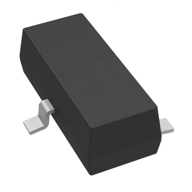
-
DRV5053VAQDBZR
Texas Instruments
-
MMC5603NJ
Memsic Inc.

-
DRV5055A1QDBZR
Texas Instruments
-
MLX90392ELQ-AAA-011-RE
Melexis Technologies NV

-
CT100LW-HS6
Allegro MicroSystems
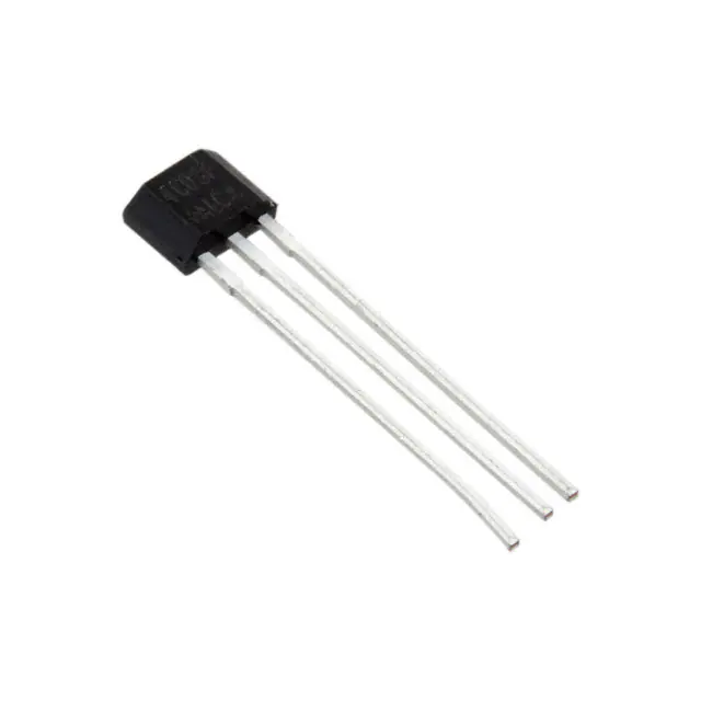
-
DRV5056A1ELPGMQ1
Texas Instruments
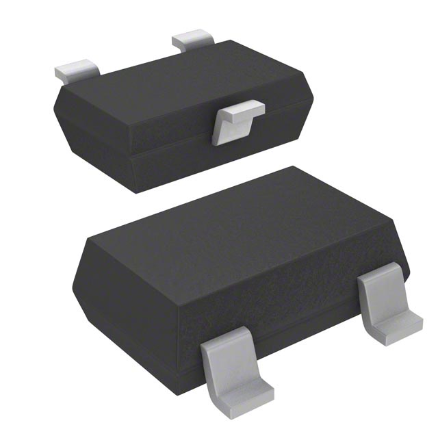
-
A1304ELHLX-T
Allegro MicroSystems
-
MMC5633NJL
Memsic Inc.
-
A1308KUA-2-T
Allegro MicroSystems
-
A1308KUA-1-T
Allegro MicroSystems
-
SI7210-B-04-IVR
Silicon Labs
-
A1308LLHLT-2-T
Allegro MicroSystems
Tech Hub

A practical engineering and sourcing framework covering lifecycle verification, lifetime-buy calculations, replacement qualification, supplier checks and counterfeit-risk controls.

TTL and CMOS logic families differ in thresholds, loading, output drive, power and timing. This engineering guide compares 74HC and 74HCT, calculates noise margins and checks 3.3 V/5 V compatibility.

A practical engineering guide to 3.3V and 5V logic compatibility, input thresholds, resistor dividers, translator ICs, MOSFET level shifting, I2C pull-ups, timing limits and power-sequencing risks.

The 74HC595 uses push-pull logic outputs, while the TPIC6B595 uses 50 V open-drain DMOS sinks for higher-power loads. This guide compares timing, current limits, 3.3 V interfacing, load wiring, thermal…

The 74HC595 converts serial data into eight stable parallel outputs. This guide covers pin functions, shift and storage timing, OE and MR behavior, drive-current limits, cascading, voltage compatibilit…

A technical comparison of level-sensitive latches and edge-triggered flip-flops, covering timing windows, setup and hold limits, master–slave operation, time borrowing, race-through, HDL inference and…

A D latch stores one bit while Enable controls when data can pass. This reference covers gate-level operation, truth tables, transparency, setup and hold timing, LE versus OE, common ICs and practical …

An SR latch stores one bit through cross-coupled feedback. This engineering reference covers NOR and NAND implementations, truth tables, forbidden-state recovery, gated operation, switch debouncing, fa…

Latch circuits retain one bit through feedback. This technical reference covers SR and D latches, truth tables, transparency, timing limits, latch-versus-flip-flop behavior, applications and common log…

An engineering guide to LED driver operation, constant-current and constant-voltage outputs, linear and switching topologies, dimming, IC selection, calculations, replacement compatibility, and fault c…


