
 My Inquiry
 My Account


Allegro MicroSystems A1333LLPTR-DD-T
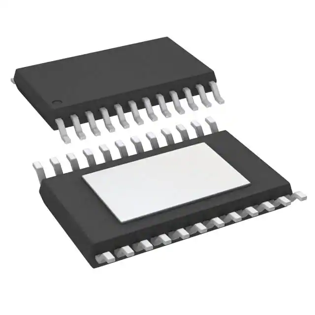
- Part No.:
- A1333LLPTR-DD-T
- Manufacturer:
- Allegro MicroSystems
- Category:
- Angle, Linear Position Measuring
- Package:
- 24-TSSOP (0.173", 4.40mm Width) Exposed Pad
- Datasheet:
-
 A1333LLPTR-DD-T.pdf
- Description:
- SENSOR ANGLE 360DEG SMD
- Quantity:
- Payment:

- Shipping:

Inventory:1,518
Please send an inquiry. Send us your inquiry, and we will respond immediately.
Product details
Overview
A1333LLPTR-DD-T from Allegro MicroSystems is a dual-die, ASIL-D-capable 360° Hall-effect angle sensor IC for safety-critical automotive systems. It delivers 12-/15-bit angular position data via SPI (up to 10 MHz), ABI/UVW outputs, and PWM (98 Hz–3.125 kHz), with ±0.4° typical angle error at 25°C and operation from –40°C to 150°C. It is used in electronic power steering (EPS) and throttle actuation where redundant sensing and diagnostic coverage are mandatory.
For engineers reviewing the A1333LLPTR-DD-T datasheet, A1333LLPTR-DD-T pinout, A1333LLPTR-DD-T application, or A1333LLPTR-DD-T equivalent, this page provides verified package mapping (24-pin eTSSOP), dual-SoC architecture details, ASIL-D integration guidance, real-time diagnostics (LBIST, ZCD path, 4-bit CRC), and confirmed alternative part selection for functional redundancy or supply continuity.
Technical Context
The A1333LLPTR-DD-T implements two independent system-on-chip (SoC) die in a single 24-pin eTSSOP package, each with its own CVH front end, ADC, digital signal processing, and dedicated SPI interface (SCLK_1/MISO_1/MOSI_1/CS_1 and SCLK_2/MISO_2/MOSI_2/CS_2). Each die supports simultaneous 12-/15-bit angle readout, programmable ABI/UVW resolution (1–2048 PPR), and independent PWM output (98 Hz–3.125 kHz).
It features dual-signal-path architecture: a high-speed PLL-based main path for low-latency angle measurement (7 µs response time) and a secondary ZCD path for turns counting, field monitoring, and cross-die diagnostic comparison. On-chip EEPROM (100 write cycles) stores calibration, zero-point offset, and configuration-accessible via SPI or VCC/PWM pin programming.
Key Specifications
| Parameter | Value and Actual Design Meaning |
|---|---|
| Angle Resolution | 12-bit (SPI/PWM) and 15-bit (ABI/UVW) - enables sub-degree precision for closed-loop motor control and high-fidelity position feedback. |
| Angle Error | ±0.4° typ. at 25°C, 300 G - ensures accurate rotor positioning in EPS without external compensation under nominal conditions. |
| Operating Temp | –40°C to +150°C - qualified for under-hood automotive environments including transmission and steering column mounting. |
| SPI Speed | Up to 10 MHz - supports low-latency, multi-device daisy-chaining on shared bus with deterministic timing. |
| PWM Range | 98 Hz to 3.125 kHz - configurable carrier frequency allows optimization for EMI filtering and microcontroller capture resolution. |
| Supply Voltage | 4.0 V to 16.5 V - direct connection to 12 V battery with ISO 7637-2 Pulse 5b tolerance up to 39 V. |
| Diagnostic Coverage | ASIL-D compliant via dual-die redundancy, LBIST, ZCD path comparison, and 4-bit SPI CRC - meets ISO 26262 SEooC requirements when integrated per safety manual. |
Pinout & Package
Package: 24-pin eTSSOP (exposed thermal pad), lead-free, 100% matte tin plating. Dual-die construction with electrically isolated power/ground domains (VCC_1/GND_1 and VCC_2/GND_2) and fully independent signal paths.
| Pin/Terminal | Circuit Role | Design Meaning |
|---|---|---|
| CS_1/SA0_1, CS_2/SA0_2 | SPI chip-select / Manchester ID LSB | Active-low enable for each die's SPI interface; double-function pin supports Manchester ID encoding when tied to BYP or GND. |
| SCLK_1, SCLK_2 | SPI clock input (die 1 & 2) | Asynchronous clock for serial communication; supports up to 10 MHz for low-latency register access. |
| MOSI_1/SA1_1, MOSI_2/SA1_2 | SPI data-in / Manchester ID MSB | Serial command/data input per die; also encodes device ID in Manchester mode via tie-off configuration. |
| MISO_1, MISO_2 | SPI data-out (die 1 & 2) | Independent readback channels allow concurrent angle/diagnostic reads from both SoCs without arbitration. |
| A_1/U_1, A_2/U_2 | Quadrature A / UVW phase U output | Configurable per die: ABI encoder output (A/B/I) or BLDC commutation signal (U/V/W); supports 1–2048 PPR. |
| PWM_1, PWM_2 | Angle-encoded PWM output (die 1 & 2) | Dedicated 12-bit PWM per die; duty cycle maps linearly to angle (5–95%), enabling simple MCU capture without SPI overhead. |
| TEST_1, TEST_2 | Test pin (die 1 & 2) | Must be tied to GND for normal operation; used during production test and LBIST activation. |
| BYP_1, BYP_2 | Internal regulator bypass (die 1 & 2) | Requires 0.1 µF ceramic capacitor per die to stabilize internal 3.3 V LDO; not intended to drive external loads. |
Key Features
| Feature | Design Value |
|---|---|
| Dual independent SoCs | Stacked die architecture improves die-to-die matching vs side-by-side layout - reduces impact of magnet misalignment on redundancy validation. |
| Programmable ABI/UVW resolution | 4-bit EEPROM field sets pulses-per-revolution (1–2048 PPR) and pole pairs (1–16), enabling one hardware design to serve multiple motor types. |
| ZCD diagnostic path | Secondary signal path updates every 32 µs for real-time cross-check against main PLL path - detects drift, saturation, or magnetic fault conditions. |
| VCC/PWM pin programming | EEPROM configuration possible using only VCC and PWM pins - eliminates need for full SPI interface during end-of-line calibration on constrained PCBs. |
| On-chip ECC | Single-bit error correction and dual-bit detection on EEPROM - ensures integrity of factory and customer calibration data over 100+ write cycles. |
Applications
| Electronic Power Steering (EPS) | Throttle Actuator Position Sensing |
|---|---|
|
Use Scenario: Real-time rotor angle feedback for brushless DC motor torque control in column-assist or rack-assist EPS modules. IC Role / Device Role / Timing Role: Primary angle sensor providing 15-bit UVW commutation signals and 12-bit SPI angle data with ≤7 µs latency to MCU. Use Value: Enables precise field-oriented control (FOC) and meets ASIL-D redundancy requirements via dual-die independent outputs and ZCD cross-validation. |
Use Scenario: Monitoring butterfly valve angular position in gasoline direct injection (GDI) throttle bodies exposed to high under-hood temperatures. IC Role / Device Role / Timing Role: Contactless 360° position sensor delivering PWM output for fast closed-loop feedback and SPI for diagnostic logging. Use Value: Operates reliably at 150°C ambient with ±0.6° max angle error, eliminating potentiometer wear and enabling fail-safe limp-home modes. |
| Rotary PRNDL Selector | Electric Brake Booster Position Feedback |
|
Use Scenario: Gear selector knob angle measurement in automatic transmission control units requiring tamper-proof, non-contact sensing. IC Role / Device Role / Timing Role: ABI quadrature output (programmable 1024 PPR) with index pulse (I/W) for absolute position initialization on power-up. Use Value: Eliminates mechanical switch bounce and contact corrosion; EEPROM-stored zero-point allows precise alignment to detent positions post-assembly. |
Use Scenario: Monitoring master cylinder pushrod displacement in electro-hydraulic brake (EHB) systems for pedal feel emulation and regenerative braking coordination. IC Role / Device Role / Timing Role: Dual-die A1333LLPTR-DD-T provides redundant 12-bit angle data streams via separate SPI buses to two safety MCUs. Use Value: Meets ASIL-D decomposition requirements through physically independent signal chains, with built-in LBIST and CRC ensuring data integrity. |
Equivalent & Alternatives
The following parts are listed as comparable options for similar angle sensing applications.
| Alternative Part | Technical Difference | Application Difference | Selection Advice |
|---|---|---|---|
| A1333LLETR-T | Single-die 14-pin TSSOP; supports ASIL-B only; no dual-SPI or redundant PWM outputs. | Used in cost-sensitive, non-redundant applications like HVAC damper control or seat position sensing. | Select when ASIL-D is not required and PCB space or BOM count must be minimized; not suitable for EPS or brake systems. |
| AMS AS5055A | Single-die 16-pin TSSOP; 14-bit resolution; SPI-only interface; no PWM or ABI/UVW outputs; ASIL-B certified. | Targeted at industrial rotary encoders and medical equipment where analog voltage output or I²C is preferred. | Choose for lower-resolution, non-automotive applications needing compact size and simpler interface; lacks dual-die redundancy and automotive qualification. |
Compared with A1333LLETR-T and AMS AS5055A, the A1333LLPTR-DD-T uniquely delivers ASIL-D compliance via stacked dual-die architecture, independent PWM/ABI/UVW outputs per die, and ZCD-based cross-die diagnostics - making it the only option qualified for primary angle sensing in EPS and brake-by-wire systems.
Availability
A1333LLPTR-DD-T is available at Aetrix Electronics and suitable for electronic power steering (EPS), throttle actuation, rotary PRNDL, and electric brake booster applications requiring stable component supply, long-term automotive lifecycle support, and ASIL-D-compliant sourcing.
Supply support for A1333LLPTR-DD-T includes scheduled delivery planning, volume procurement assistance, BOM continuity management, traceable sourcing, and lifecycle availability coordination for OEM customers, industrial embedded developers, connected-device designers, and electronics production programs.
Manufacturer
Allegro MicroSystems designs high-performance magnetic sensing and power ICs for automotive and industrial motion control. Founded in 1985, it specializes in Hall-effect, current-sensing, and motor driver solutions with deep expertise in functional safety.
The A1333 product line was developed specifically for ASIL-D automotive angle sensing, integrating dual-die redundancy, on-chip diagnostics, and EEPROM-programmable interfaces to replace legacy resolver and potentiometer-based systems in EPS and transmission controls.
FAQ
What safety standard compliance does the A1333LLPTR-DD-T support?
The A1333LLPTR-DD-T is developed as an ASIL-D safety element out of context (SEooC) per ISO 26262, with dual-die architecture, LBIST, ZCD path comparison, and 4-bit SPI CRC. Its ASIL-D compliance requires integration per the A1333 Safety Manual - including system-level watchdogs, independent power domains, and fault-handling logic in the host MCU. The A1333LLPTR-DD-T itself is not "certified" but qualifies as a compliant SEooC building block.
How is redundancy implemented in the A1333LLPTR-DD-T?
Redundancy in the A1333LLPTR-DD-T is achieved via two physically independent SoC die in one 24-pin eTSSOP package, each with separate VCC/GND pins, SPI interfaces, PWM outputs, and ABI/UVW drivers. Die-to-die matching is enhanced by stacked orientation - reducing sensitivity to magnet misalignment compared to side-by-side layouts. Cross-die validation uses the ZCD path for real-time consistency checks.
Can the A1333LLPTR-DD-T operate directly from a 12 V battery?
Yes, the A1333LLPTR-DD-T operates from 4.0 V to 16.5 V and withstands ISO 7637-2 Pulse 5b transients up to 39 V. Its internal regulator accepts raw battery input, and BYP_1/BYP_2 pins require 0.1 µF ceramic capacitors for stabilization. No external pre-regulator is needed for 12 V automotive battery connection - simplifying power design in EPS and throttle modules.
What output formats does the A1333LLPTR-DD-T support?
The A1333LLPTR-DD-T supports four concurrent output formats per die: 10 MHz SPI (12-/15-bit angle + diagnostics), programmable PWM (98 Hz–3.125 kHz, 12-bit), ABI quadrature (1–2048 PPR), and UVW BLDC commutation (1–16 pole pairs). All outputs are independently configurable via EEPROM, allowing mixed-mode use - e.g., SPI for diagnostics and PWM for real-time control.
Is EEPROM programming possible without a full SPI interface?
Yes, the A1333LLPTR-DD-T supports EEPROM programming over VCC and PWM pins - a feature called "pin-programming mode." By applying specific voltage sequences to VCC while toggling PWM, users can write calibration data and configuration bits without connecting MOSI/MISO/SCLK/CS. This enables in-system calibration on PCBs with minimal pin count, such as throttle bodies with only PWM and power connections.
A1333LLPTR-DD-T Specifications
- Product attributes
- Attribute value
- Manufacturer:
- Allegro MicroSystems
- Package/Case:
- 24-TSSOP (0.173", 4.40mm Width) Exposed Pad
- Series:
- -
- Packaging:
- Tape & Reel (TR)
- Product Status:
- Active
- Programmable:
- -
- For Measuring:
- Angle
- Technology:
- Hall Effect
- Rotation Angle - Electrical, Mechanical:
- 0° ~ 360°, Continuous
- Linear Range:
- -
- Output:
- PWM, SPI
- Output Signal:
- Programmable
- Actuator Type:
- External Magnet, Not Included
- Linearity:
- -
- Resistance:
- -
- Resistance Tolerance:
- -
- Voltage - Supply:
- 4V ~ 16.5V
- Mounting Type:
- Surface Mount
- Termination Style:
- Gull Wing
- Operating Temperature:
- -40°C ~ 150°C (TA)
- Grade:
- -
- Qualification:
- -
- Supplier Device Package:
- 24-TSSOP-EP
A1333LLPTR-DD-T FAQ
1.How can I place an order for A1333LLPTR-DD-T through Aetrix?
Please submit a Request for Quotation (RFQ) for A1333LLPTR-DD-T on Aetrix. Our sales agent will provide a competitive quotation and guide you through the order confirmation once you accept the terms.
2.Are the price and stock information for A1333LLPTR-DD-T reliable?
The price and inventory of A1333LLPTR-DD-T are updated periodically and may fluctuate due to market conditions. Stock and pricing data are typically refreshed every 24 hours. Quotation validity for A1333LLPTR-DD-T is usually 5 days.
3.What payment methods are accepted for A1333LLPTR-DD-T?
We accept Wire Transfer, PayPal, Credit Card, Western Union, MoneyGram, and Escrow for A1333LLPTR-DD-T transactions.
Note: Certain payment methods may incur a processing fee.
4.How is shipping managed for A1333LLPTR-DD-T?
A1333LLPTR-DD-T orders can be shipped via leading logistics carriers, including DHL, UPS, FedEx, TNT, or Registered Mail.
Once your A1333LLPTR-DD-T order is processed, you will receive an email with the shipment details and tracking number.
Note: Tracking information may take up to 24 hours to appear. Express delivery typically takes 3–5 business days.
5.How can I obtain technical support or documentation for A1333LLPTR-DD-T?
For technical support, including A1333LLPTR-DD-T datasheets, pinout diagrams, or application guidance, please contact our engineering support team. They can provide detailed documentation and assistance for your A1333LLPTR-DD-T requirements.
6.How does Aetrix verify that A1333LLPTR-DD-T is sourced from the original manufacturer or authorized distributors?
All A1333LLPTR-DD-T products on Aetrix are procured from qualified distributors and authorized channels. Our dedicated quality assurance team conducts strict verification, including traceability checks and, if necessary, third-party testing. This ensures that A1333LLPTR-DD-T meets industry standards.
7.What is the process for return or replacement of A1333LLPTR-DD-T?
All A1333LLPTR-DD-T units undergo pre-shipment inspection (PSI). If there is an issue with A1333LLPTR-DD-T, returns or replacements are accepted under the following conditions:
1.Quantity discrepancies, incorrect items, or visible external defects (such as breakage or corrosion), acknowledged by Aetrix.
2.The issue is reported within 90 days of delivery.
3.The A1333LLPTR-DD-T part is unused and in its original packaging.
Return procedure for A1333LLPTR-DD-T:
1.Submit a request within 90 days.
2.Obtain a Return Material Authorization (RMA) from Aetrix.
A1333LLPTR-DD-T Tags
-
TLV493DA1B6HTSA2
Infineon Technologies
-
EVW-AE4001B14
Panasonic Electronic Components
-
3382G-1-103G
Bourns Inc.
-
TLE5501E0001XUMA1
Infineon Technologies
-
HAL830UT-A
TDK-Micronas GmbH
-
TLE5009E1000FUMA1
Infineon Technologies
-
TLE5501E0002XUMA1
Infineon Technologies
-
HAL3725DJ-A
TDK-Micronas GmbH
-
HAL3727DJ-A
TDK-Micronas GmbH
-
HMC1501-TR
Honeywell Aerospace
-
HMC1512-TR
Honeywell Aerospace

-
AAS33001LLEATR-5
Allegro MicroSystems
Tech Hub

A practical engineering and sourcing framework covering lifecycle verification, lifetime-buy calculations, replacement qualification, supplier checks and counterfeit-risk controls.

TTL and CMOS logic families differ in thresholds, loading, output drive, power and timing. This engineering guide compares 74HC and 74HCT, calculates noise margins and checks 3.3 V/5 V compatibility.

A practical engineering guide to 3.3V and 5V logic compatibility, input thresholds, resistor dividers, translator ICs, MOSFET level shifting, I2C pull-ups, timing limits and power-sequencing risks.

The 74HC595 uses push-pull logic outputs, while the TPIC6B595 uses 50 V open-drain DMOS sinks for higher-power loads. This guide compares timing, current limits, 3.3 V interfacing, load wiring, thermal…

The 74HC595 converts serial data into eight stable parallel outputs. This guide covers pin functions, shift and storage timing, OE and MR behavior, drive-current limits, cascading, voltage compatibilit…

A technical comparison of level-sensitive latches and edge-triggered flip-flops, covering timing windows, setup and hold limits, master–slave operation, time borrowing, race-through, HDL inference and…

A D latch stores one bit while Enable controls when data can pass. This reference covers gate-level operation, truth tables, transparency, setup and hold timing, LE versus OE, common ICs and practical …

An SR latch stores one bit through cross-coupled feedback. This engineering reference covers NOR and NAND implementations, truth tables, forbidden-state recovery, gated operation, switch debouncing, fa…

Latch circuits retain one bit through feedback. This technical reference covers SR and D latches, truth tables, transparency, timing limits, latch-versus-flip-flop behavior, applications and common log…

An engineering guide to LED driver operation, constant-current and constant-voltage outputs, linear and switching topologies, dimming, IC selection, calculations, replacement compatibility, and fault c…


