
 My Inquiry
 My Account


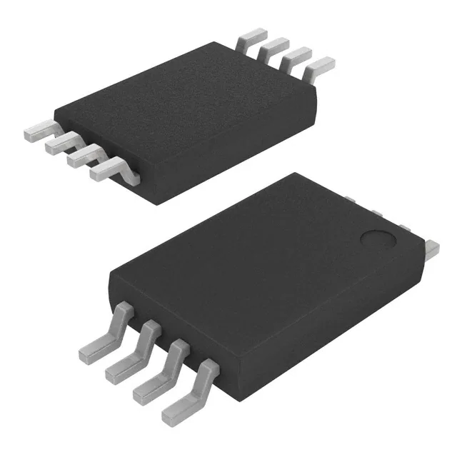
Allegro MicroSystems A1359LLETR-RP-T
- Part No.:
- A1359LLETR-RP-T
- Manufacturer:
- Allegro MicroSystems
- Category:
- Linear, Compass (ICs)
- Package:
- 8-TSSOP (0.173", 4.40mm Width)
- Datasheet:
-
 A1359LLETR-RP-T.pdf
- Description:
- SENSOR HALL ANALOG/PWM 8TSSOP
- Quantity:
- Payment:

- Shipping:

Inventory:3,320
Please send an inquiry. Send us your inquiry, and we will respond immediately.
Product details
Overview
A1359LLETR-RP-T from Allegro MicroSystems is a factory-programmed, dual-output linear Hall-effect sensor IC with analog voltage and pulse-width-modulated (PWM) outputs, reverse-polarity configuration (output voltage increases with north magnetic field), ±8.73–9.27 mV/G sensitivity at 25°C, ratiometric operation over 4.5–5.5 V supply, and –40°C to 150°C operating range-used in automotive throttle position and brake pedal sensing for redundancy-critical safety systems.
For engineers reviewing the A1359LLETR-RP-T datasheet, A1359LLETR-RP-T pinout, A1359LLETR-RP-T application, or A1359LLETR-RP-T equivalent, this page delivers verified electrical specs, terminal roles, thermal derating data, factory-programmed polarity and temperature coefficients, and real-world error budgeting for dual-channel mismatch and ratiometry compliance.
Technical Context
The A1359LLETR-RP-T integrates a BiCMOS monolithic circuit with Hall element, dynamic offset cancellation via high-speed chopping (400 kHz typical), temperature-compensated amplifier, and dual independent signal paths-one for analog output (VOUT) and one for PWM generation (PWMOUT)-with matched sensitivity and quiescent point calibration across temperature.
Its reverse-polarity programming means VOUT decreases under south-field exposure and increases under north-field exposure; QVO is factory-set to 2.5 V nominal, QD to 50% duty cycle, and both TCSENS (0.08–0.16 %/°C) and QVO/QD temperature coefficients are end-of-line programmed at Allegro for application-specific accuracy optimization.
Key Specifications
| Parameter | Value and Actual Design Meaning |
|---|---|
| Output Type | Dual: analog voltage (ratiometric, 2.5 V QVO) + open-drain PWM (4 kHz carrier, 50% QD) |
| Sensitivity | –9.0 mV/G typical at 25°C; negative sign denotes reverse polarity (voltage rises with north field) |
| Supply Voltage | 4.5–5.5 V; undervoltage lockout active below 2.5 V (off) and above 3 V (on) |
| Operating Temp | –40°C to 150°C ambient; junction max 165°C; thermal resistance 145 °C/W on 4-layer PCB |
| Output Mismatch | ±57.4 mV over 1.75–3.25 V analog range; ±85 mV at extremes-enables fault detection via cross-channel comparison |
| Response Time | 500 µs for analog output; 1.5 ms for PWM output-supports real-time position feedback in fast-actuating systems |
| Quiescent Drift | ±17 mV over full temperature range-guaranteed by factory TC programming, not inherent drift |
Pinout & Package
Package: 8-pin TSSOP (suffix LE), surface-mount, lead-free, 100% matte-tin plating, 6.4 mm × 4.4 mm footprint.
| Pin/Terminal | Circuit Role | Design Meaning |
|---|---|---|
| 1 (PWMOUT) | Open-drain PWM output | Requires external pull-up; sinks up to 25 mA; clamped at 28 V; used for noise-immune digital position reporting |
| 2 (VCC) | Power supply input | 4.5–5.5 V; must be bypassed with 100 nF capacitor to GND; internal Zener clamp at 6–8.3 V |
| 3, 5, 6, 8 (NC) | No-connect terminals | Must be tied to GND or VCC per layout guidelines; no internal connection; improves EMC when grounded |
| 4 (VOUT) | Analog voltage output | Ratiometric, 0.5–4.5 V swing; low-impedance (<1 Ω); short-circuit clamped at 0.4–0.7 V (low) and 4.25–4.65 V (high) |
| 7 (GND) | Device ground reference | Primary return path for supply and outputs; must be low-inductance connection for stable chopper operation |
Key Features
| Feature | Design Value |
|---|---|
| Dual tracking outputs | Analog and PWM channels share identical magnetic response-enables real-time cross-check for ASIL-B/C fault detection |
| Factory-programmed polarity | Reverse polarity (RP) means output voltage increases with north-field exposure-required for specific mechanical mounting orientations |
| Chopping stabilization | 400 kHz modulation eliminates thermal and stress-induced QVO drift-delivers ±17 mV total drift over –40°C to 150°C |
| Output voltage clamps | VOUT clamped at 0.4–0.7 V (low) and 4.25–4.65 V (high)-provides diagnostic indication of short-circuit or overload conditions |
| EMC-hardened design | Integrated filtering, layout-optimized bond wires, and differential sensing reduce radiated emissions-meets stringent automotive CISPR-25 Class 5 |
Applications
| Throttle Position Sensing | Brake Pedal Position Sensing |
|---|---|
Use Scenario: Measures angular displacement of engine throttle valve in gasoline direct injection systems. IC Role / Device Role / Timing Role: Dual-output Hall sensor providing redundant analog and PWM signals synchronized to ECU sampling clocks. Use Value: Enables ISO 26262 ASIL-B compliant position monitoring with <500 µs analog response and built-in mismatch diagnostics. | Use Scenario: Detects linear travel of vehicle brake pedal for electronic stability control (ESC) and regenerative braking coordination. IC Role / Device Role / Timing Role: Reverse-polarity linear Hall sensor delivering correlated analog voltage and PWM duty cycle proportional to pedal stroke. Use Value: Supports fail-safe operation via cross-channel validation; clamped outputs detect wiring faults before system shutdown. |
| Steering Angle Sensing | Transmission Gear Selector |
Use Scenario: Monitors rotary position of steering column for electric power steering (EPS) torque assist algorithms. IC Role / Device Role / Timing Role: High-accuracy linear Hall IC with factory-optimized TCSENS and QVO drift compensation for long-term stability. Use Value: Maintains ±0.5% linearity error and ±0.5% ratiometry error across 15-year vehicle life-reducing recalibration needs. | Use Scenario: Determines mechanical detent position in automatic transmission shift-by-wire actuators. IC Role / Device Role / Timing Role: Dual-output sensor interfacing directly to microcontroller ADC and timer capture inputs without external conditioning. Use Value: Eliminates need for separate analog-to-digital conversion and PWM decoding logic-reducing BOM count and PCB area. |
Equivalent & Alternatives
The following parts are listed as comparable options for similar linear Hall-effect sensor applications.
| Alternative Part | Technical Difference | Application Difference | Selection Advice |
|---|---|---|---|
| A1359LLETR-RP-MS-T | Same die, same RP polarity, but shipped in moisture-sensitive (MS) packaging with dry-pack requirements | Identical electrical performance; differs only in tape-and-reel moisture barrier specification | Select for high-humidity assembly environments or extended storage prior to reflow |
| ACS724LLCTR-20AU-T | Current sensor (not position sensor); 20 A range; single analog output; no PWM; ±1.5% total error band | Measures current flow-not magnetic field strength-so unsuitable for non-contact position sensing | Only consider if application requires current measurement instead of angular/linear displacement |
Compared with A1359LLETR-RP-MS-T, the A1359LLETR-RP-T offers identical sensing performance but relaxed handling requirements; compared with ACS724LLCTR-20AU-T, it provides true contactless position sensing with dual-output redundancy-critical for functional safety architectures where current sensing cannot substitute for field-based position detection.
Availability
A1359LLETR-RP-T is available at Aetrix Electronics and suitable for automotive throttle position sensing, brake pedal monitoring, steering angle measurement, and transmission gear selector applications requiring stable component supply across extended temperature ranges and long product lifecycles.
Supply support for A1359LLETR-RP-T includes scheduled delivery planning, volume procurement assistance, BOM continuity management, traceable sourcing, and lifecycle availability coordination for OEM customers, industrial embedded developers, connected-device designers, and electronics production programs.
Manufacturer
Allegro MicroSystems is a U.S.-based semiconductor company specializing in magnetic sensing, power ICs, and precision motion control solutions for automotive and industrial markets.
The A1359 product line delivers factory-programmed, dual-output linear Hall-effect sensors optimized for functional safety–critical position sensing in harsh environments-designed to meet ASIL-B requirements without external calibration.
FAQ
What is the magnetic polarity configuration of the A1359LLETR-RP-T?
The A1359LLETR-RP-T is factory-programmed with reverse polarity (RP), meaning its analog output voltage increases in response to an increasing north-polarity magnetic field applied perpendicular to the branded surface of the package. This is confirmed in the Selection Guide and Electrical Characteristics table, where sensitivity is specified as –9.0 mV/G at 25°C. The A1359LLETR-RP-T maintains this behavior across its full operating temperature range due to end-of-line TCSENS programming.
Does the A1359LLETR-RP-T require external components for basic operation?
Yes-the A1359LLETR-RP-T requires a 100 nF bypass capacitor between VCC (pin 2) and GND (pin 7), and a pull-up resistor (2 kΩ typical) on PWMOUT (pin 1) for proper open-drain operation. The datasheet Figure 7 shows these as mandatory; omitting the bypass capacitor risks instability in the chopper-stabilized amplifier, while missing the pull-up prevents valid PWM signal generation. No external components are needed for VOUT (pin 4), which drives low-impedance loads directly.
How does the A1359LLETR-RP-T achieve ±0.5% ratiometry error across supply voltage variation?
The A1359LLETR-RP-T achieves ±0.5% ratiometry error through factory trimming of internal gain and offset circuits during end-of-line test, ensuring that quiescent voltage output (VOUT(Q)), sensitivity (Sens), and clamp voltages (VCLPH/VCLPL) scale linearly with VCC across 4.5–5.5 V. This is verified per Equation 11–13 in the Characteristic Definitions section and applies only to the analog channel; the PWM channel inherently maintains 50% QD across the same supply range due to duty-cycle normalization.
Can the A1359LLETR-RP-T be used in ASIL-B or ASIL-C automotive systems?
Yes-the A1359LLETR-RP-T supports ASIL-B and ASIL-C system integration through its dual-output architecture, programmable error detection thresholds (e.g., ±57.4 mV analog–PWM mismatch), short-circuit diagnostic clamps, and guaranteed drift performance (±17 mV QVO over temperature). While the device itself is not ISO 26262-certified, its specifications enable system-level compliance when combined with appropriate MCU-level monitoring and fault-handling logic per ISO 26262-5 Annex D.
What is the maximum allowable load capacitance on the VOUT pin of the A1359LLETR-RP-T?
The maximum allowable load capacitance on the VOUT pin (pin 4) of the A1359LLETR-RP-T is 10 nF, as specified in the Electrical Characteristics table under "Output Load Capacitance." Exceeding this value degrades settling time and may cause oscillation due to phase margin loss in the output stage. For capacitive loads >10 nF, an external buffer amplifier is required-this limit is independent of load resistance, which is specified separately as ≥4.7 kΩ.
A1359LLETR-RP-T Specifications
- Product attributes
- Attribute value
- Manufacturer:
- Allegro MicroSystems
- Series:
- -
- Package/Case:
- 8-TSSOP (0.173", 4.40mm Width)
- Packaging:
- Tape & Reel (TR)
- Product Status:
- Last Time Buy
- Technology:
- Hall Effect
- Axis:
- Single
- Output Type:
- Analog Voltage, PWM
- Sensing Range:
- -
- Voltage - Supply:
- 4.5V ~ 5.5V
- Current - Supply (Max):
- 13.5mA
- Current - Output (Max):
- 10mA
- Resolution:
- -
- Bandwidth:
- 2kHz
- Operating Temperature:
- -40°C ~ 150°C
- Grade:
- -
- Qualification:
- -
- Features:
- Temperature Compensated
- Supplier Device Package:
- 8-TSSOP
- Mounting Type:
- Surface Mount
A1359LLETR-RP-T FAQ
1.How can I place an order for A1359LLETR-RP-T through Aetrix?
Please submit a Request for Quotation (RFQ) for A1359LLETR-RP-T on Aetrix. Our sales agent will provide a competitive quotation and guide you through the order confirmation once you accept the terms.
2.Are the price and stock information for A1359LLETR-RP-T reliable?
The price and inventory of A1359LLETR-RP-T are updated periodically and may fluctuate due to market conditions. Stock and pricing data are typically refreshed every 24 hours. Quotation validity for A1359LLETR-RP-T is usually 5 days.
3.What payment methods are accepted for A1359LLETR-RP-T?
We accept Wire Transfer, PayPal, Credit Card, Western Union, MoneyGram, and Escrow for A1359LLETR-RP-T transactions.
Note: Certain payment methods may incur a processing fee.
4.How is shipping managed for A1359LLETR-RP-T?
A1359LLETR-RP-T orders can be shipped via leading logistics carriers, including DHL, UPS, FedEx, TNT, or Registered Mail.
Once your A1359LLETR-RP-T order is processed, you will receive an email with the shipment details and tracking number.
Note: Tracking information may take up to 24 hours to appear. Express delivery typically takes 3–5 business days.
5.How can I obtain technical support or documentation for A1359LLETR-RP-T?
For technical support, including A1359LLETR-RP-T datasheets, pinout diagrams, or application guidance, please contact our engineering support team. They can provide detailed documentation and assistance for your A1359LLETR-RP-T requirements.
6.How does Aetrix verify that A1359LLETR-RP-T is sourced from the original manufacturer or authorized distributors?
All A1359LLETR-RP-T products on Aetrix are procured from qualified distributors and authorized channels. Our dedicated quality assurance team conducts strict verification, including traceability checks and, if necessary, third-party testing. This ensures that A1359LLETR-RP-T meets industry standards.
7.What is the process for return or replacement of A1359LLETR-RP-T?
All A1359LLETR-RP-T units undergo pre-shipment inspection (PSI). If there is an issue with A1359LLETR-RP-T, returns or replacements are accepted under the following conditions:
1.Quantity discrepancies, incorrect items, or visible external defects (such as breakage or corrosion), acknowledged by Aetrix.
2.The issue is reported within 90 days of delivery.
3.The A1359LLETR-RP-T part is unused and in its original packaging.
Return procedure for A1359LLETR-RP-T:
1.Submit a request within 90 days.
2.Obtain a Return Material Authorization (RMA) from Aetrix.
A1359LLETR-RP-T Tags
-
DRV5053VAQDBZR
Texas Instruments
-
MMC5603NJ
Memsic Inc.

-
DRV5055A1QDBZR
Texas Instruments
-
MLX90392ELQ-AAA-011-RE
Melexis Technologies NV

-
CT100LW-HS6
Allegro MicroSystems
-
DRV5056A1ELPGMQ1
Texas Instruments
-
A1304ELHLX-T
Allegro MicroSystems
-
MMC5633NJL
Memsic Inc.
-
A1308KUA-2-T
Allegro MicroSystems
-
A1308KUA-1-T
Allegro MicroSystems
-
SI7210-B-04-IVR
Silicon Labs
-
A1308LLHLT-2-T
Allegro MicroSystems
Tech Hub

A practical engineering and sourcing framework covering lifecycle verification, lifetime-buy calculations, replacement qualification, supplier checks and counterfeit-risk controls.

TTL and CMOS logic families differ in thresholds, loading, output drive, power and timing. This engineering guide compares 74HC and 74HCT, calculates noise margins and checks 3.3 V/5 V compatibility.

A practical engineering guide to 3.3V and 5V logic compatibility, input thresholds, resistor dividers, translator ICs, MOSFET level shifting, I2C pull-ups, timing limits and power-sequencing risks.

The 74HC595 uses push-pull logic outputs, while the TPIC6B595 uses 50 V open-drain DMOS sinks for higher-power loads. This guide compares timing, current limits, 3.3 V interfacing, load wiring, thermal…

The 74HC595 converts serial data into eight stable parallel outputs. This guide covers pin functions, shift and storage timing, OE and MR behavior, drive-current limits, cascading, voltage compatibilit…

A technical comparison of level-sensitive latches and edge-triggered flip-flops, covering timing windows, setup and hold limits, master–slave operation, time borrowing, race-through, HDL inference and…

A D latch stores one bit while Enable controls when data can pass. This reference covers gate-level operation, truth tables, transparency, setup and hold timing, LE versus OE, common ICs and practical …

An SR latch stores one bit through cross-coupled feedback. This engineering reference covers NOR and NAND implementations, truth tables, forbidden-state recovery, gated operation, switch debouncing, fa…

Latch circuits retain one bit through feedback. This technical reference covers SR and D latches, truth tables, transparency, timing limits, latch-versus-flip-flop behavior, applications and common log…

An engineering guide to LED driver operation, constant-current and constant-voltage outputs, linear and switching topologies, dimming, IC selection, calculations, replacement compatibility, and fault c…


