
 My Inquiry
 My Account


Allegro MicroSystems A1445EEWLT-P
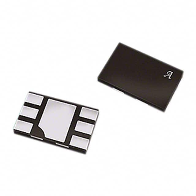
- Part No.:
- A1445EEWLT-P
- Manufacturer:
- Allegro MicroSystems
- Category:
- Motor Drivers, Controllers
- Package:
- 6-XFDFN Exposed Pad
- Datasheet:
-
 A1445EEWLT-P.pdf
- Description:
- IC MOTOR DRIVER 1.8V-4.2V 6DFN
- Quantity:
- Payment:

- Shipping:

Inventory:3,047
Please send an inquiry. Send us your inquiry, and we will respond immediately.
Product details
Overview
A1445EEWLT-P from Allegro MicroSystems is a low-voltage full-bridge brushless DC motor driver with integrated Hall element, soft switching, reverse battery protection, and externally controlled speed regulation via PDC pin. It operates from 1.8 V to 4.2 V, delivers ±250 mA continuous output current, and features unidirectional rotation, antistall recovery, and micropower sleep mode - designed for vibration motor control in cellular phones and handheld game controllers.
For engineers reviewing the A1445EEWLT-P datasheet, A1445EEWLT-P pinout, A1445EEWLT-P application, or A1445EEWLT-P equivalent, key selection criteria include its 6-pin MLP/DFN (1.5 mm × 2 mm) package, Hall-based commutation, selectable internal PWM duty cycle (71–89%), thermal shutdown at 165 °C, and compatibility with fast start-stop cycles in space-constrained portable electronics.
Technical Context
The A1445EEWLT-P integrates a Hall sensor, full-bridge driver, chopper-stabilized signal conditioning, and PWM speed control logic on a single CMOS die. Its soft switching algorithm controls slew rate on both outputs to reduce EMI and audible noise, while the antistall feature actively detects rotor stall and initiates restart sequences without external intervention.
Speed regulation is implemented via analog voltage level on the PDC pin, selecting among three discrete internal PWM duty cycles (71%, 80%, or 89%). The SLEEP pin enables braking (reversing bridge polarity briefly) followed by micropower sleep mode (<10 µA), eliminating need for external FETs in battery-powered systems.
Key Specifications
| Parameter | Value and Actual Design Meaning |
|---|---|
| Supply Voltage Range | 1.8 V to 4.2 V - enables operation directly from single Li-ion or NiMH cells without LDO |
| Continuous Output Current | ±250 mA - supports compact vibration motors and low-power fans up to ~5 V rating |
| Internal PWM Frequency | 40 kHz - high enough to avoid audible noise, low enough for efficient MOSFET switching |
| PWM Duty Cycle Options | 71%, 80%, 89% - selected by PDC pin voltage, enabling precise speed tuning across motor loads |
| Thermal Shutdown Threshold | 165 °C with 20 °C hysteresis - protects against sustained overloads and PCB-level thermal runaway |
| Hall Switchpoints | BOP = 35–75 G, BRP = –75 to –35 G - ensures reliable commutation with standard ring magnets |
| Sleep Mode Current | <10 µA - extends battery life in always-on portable devices during idle periods |
Pinout & Package
Package: 6-contact MLP/DFN (EW), 1.5 mm × 2 mm footprint, 0.38 mm nominal height, with exposed thermal pad for enhanced heat dissipation in high-density layouts.
| Pin/Terminal | Circuit Role | Design Meaning |
|---|---|---|
| VDD | Positive supply input | Accepts 1.8–4.2 V; includes reverse battery protection - no external diode required |
| SLEEP | Enable/brake/sleep control input | Active-low; initiates braking then enters <10 µA sleep mode - eliminates external power-switching FET |
| PDC | Programmable duty cycle select | Analog input (0–VDD); sets internal PWM duty cycle to 71%, 80%, or 89% for speed calibration |
| GND | Power and signal reference | Common return path for supply, Hall sensing, and output bridge; connects to exposed thermal pad |
| VOUT1 | Bridge output terminal 1 | Drives one side of BLDC motor coil; complementary to VOUT2; rated for ±500 mA peak |
| VOUT2 | Bridge output terminal 2 | Drives opposite side of motor coil; enables unidirectional rotation via Hall-commutated full-bridge |
Key Features
| Feature | Design Value |
|---|---|
| Chopper-stabilized Hall sensing | Reduces offset drift over –40 °C to +85 °C, ensuring consistent commutation across temperature |
| Soft switching slew-rate control | Minimizes EMI emissions and audible coil whine in noise-sensitive handheld applications |
| Integrated reverse battery protection | Blocks –5.0 V reverse supply without external components - simplifies PCB layout and BOM |
| Antistall algorithm | Automatically attempts motor restart upon stall detection - improves reliability in jam-prone mechanisms |
| Unidirectional operation mode | Guarantees fixed rotation direction - eliminates need for direction-control logic in vibration actuators |
Applications
| Vibration Motor Control | Low-Power Fan Drive |
|---|---|
Use Scenario: Haptic feedback generation in smartphones and wearable devices requiring rapid motor start-stop cycles. IC Role / Device Role / Timing Role: Full-bridge driver with Hall commutation and soft switching - provides precise timing-synchronized rotor position feedback and torque control. Use Value: Enables <100 ms restart delay and <160 µs Hall settling time for responsive tactile feedback without audible artifacts. | Use Scenario: Thermal management in portable medical monitors and handheld test equipment using 5 V-rated micro-fans. IC Role / Device Role / Timing Role: Low-voltage motor controller with externally adjustable PWM duty cycle - regulates fan speed based on temperature sensor output. Use Value: Delivers stable 71–89% duty cycle options via PDC pin, supporting fine-grained airflow control down to 1.8 V supply. |
| Portable Gaming Controller Actuation | Pager Motor Driver |
Use Scenario: Force-feedback triggers and rumble motors in Bluetooth-enabled game controllers with strict power budget constraints. IC Role / Device Role / Timing Role: Micropower motor driver with sleep mode - activates only during user interaction, reducing average system current. Use Value: Achieves <10 µA sleep current and fast wake-up (<100 ms), extending battery life without sacrificing responsiveness. | Use Scenario: Alert vibration in legacy pagers where board space and component count are critical design constraints. IC Role / Device Role / Timing Role: Single-chip Hall-commutated driver - replaces discrete Hall sensor + H-bridge + control logic. Use Value: Integrates reverse battery, short-circuit, and thermal protection - eliminates 3–4 external protection components per motor channel. |
Equivalent & Alternatives
The following parts are listed as comparable options for similar low-voltage BLDC motor driver applications.
| Alternative Part | Technical Difference | Application Difference | Selection Advice |
|---|---|---|---|
| A1442 | No integrated Hall element; requires external Hall sensor; lower supply range (1.6–3.6 V) | Suitable for designs needing flexible magnetic sensing placement or higher temperature operation (–40 °C to +125 °C) | Select when Hall sensor location must be decoupled from driver IC or extended temperature range is required |
| A1448 | Includes bidirectional rotation capability; higher continuous current (±350 mA); same 1.8–4.2 V range | Required for applications needing reversible motor motion (e.g., optical zoom actuators, dual-direction haptics) | Choose when motor direction reversal is essential and higher drive strength justifies larger footprint |
Compared with A1445EEWLT-P, the A1442 lacks on-die Hall sensing and operates at lower voltage, making it less suitable for compact single-cell vibration systems; the A1448 adds bidirectional control and higher current but increases complexity and cost where unidirectional operation suffices.
Availability
A1445EEWLT-P is available at Aetrix Electronics and suitable for vibration motor control, portable gaming actuation, pager alert systems, and low-power fan drive applications requiring stable component supply despite its Last Time Buy status.
Supply support for A1445EEWLT-P includes scheduled delivery planning, volume procurement assistance, BOM continuity management, traceable sourcing, and lifecycle availability coordination for OEM customers, industrial embedded developers, connected-device designers, and electronics production programs.
Manufacturer
Allegro MicroSystems is a U.S.-based semiconductor company specializing in high-performance magnetic sensing and power ICs for motion control, automotive, and industrial applications.
The A1445 belongs to Allegro's low-voltage BLDC motor driver product line, engineered specifically for space-constrained portable electronics requiring integrated Hall commutation, ultra-low power sleep, and robust fault protection.
FAQ
What is the operating voltage range for the A1445EEWLT-P?
The A1445EEWLT-P operates from 1.8 V to 4.2 V, supporting direct connection to single-cell Li-ion or NiMH batteries. Extended functionality down to 1.8 V includes full Hall sensing and PWM control, though magnetic switchpoints and RDS(on) exhibit slight variation at the lower end. This range makes the A1445EEWLT-P ideal for battery-powered portable devices where supply headroom is minimal.
How does the PDC pin control motor speed in the A1445EEWLT-P?
The PDC pin on the A1445EEWLT-P selects among three discrete internal PWM duty cycles: 71% (PDC < 0.5 V), 80% (PDC floating), or 89% (PDC > VDD–0.5 V). This analog-level programming allows precise speed calibration without external microcontroller intervention. The A1445EEWLT-P uses this setting to regulate maximum motor RPM during Hall-commutated operation above the SROT threshold.
Does the A1445EEWLT-P support bidirectional motor rotation?
No, the A1445EEWLT-P operates exclusively in unidirectional mode - it drives the motor in one fixed direction only. This design choice simplifies control logic and reduces silicon area, making it optimal for vibration motors and alert actuators. For bidirectional applications, Allegro recommends the A1448, which shares the same package and voltage range but adds direction control capability.
What protection features are integrated into the A1445EEWLT-P?
The A1445EEWLT-P integrates reverse battery protection (–5.0 V on VDD), output short-circuit protection, thermal shutdown at 165 °C with 20 °C hysteresis, and antistall recovery. These functions eliminate the need for external protection components like reverse-polarity diodes or current-sense resistors, reducing BOM count and PCB area - a key advantage in miniaturized portable designs using the A1445EEWLT-P.
Is the A1445EEWLT-P still recommended for new designs?
No - the A1445EEWLT-P is classified as "Not for New Design" with Last Time Buy status effective May 4, 2009. Allegro recommends transitioning to the A1442 or A1448 for new applications. However, Aetrix Electronics continues to support existing designs with traceable inventory, lifecycle coordination, and volume procurement assistance for the A1445EEWLT-P where legacy compatibility is required.
A1445EEWLT-P Specifications
- Product attributes
- Attribute value
- Manufacturer:
- Allegro MicroSystems
- Series:
- -
- Package/Case:
- 6-XFDFN Exposed Pad
- Packaging:
- Tape & Reel (TR)
- Product Status:
- Obsolete
- Motor Type - Stepper:
- -
- Motor Type - AC, DC:
- Brushless DC (BLDC)
- Function:
- Driver - Fully Integrated, Control and Power Stage
- Output Configuration:
- Half Bridge (2)
- Interface:
- On/Off
- Technology:
- CMOS
- Step Resolution:
- -
- Applications:
- Haptic Feedback
- Current - Output:
- 250mA
- Voltage - Supply:
- 1.8V ~ 4.2V
- Voltage - Load:
- 1.8V ~ 4.2V
- Operating Temperature:
- -40°C ~ 165°C (TJ)
- Grade:
- -
- Qualification:
- -
- Mounting Type:
- Surface Mount
- Supplier Device Package:
- 6-DFN/MLP (1.5x2)
A1445EEWLT-P FAQ
1.How can I place an order for A1445EEWLT-P through Aetrix?
Please submit a Request for Quotation (RFQ) for A1445EEWLT-P on Aetrix. Our sales agent will provide a competitive quotation and guide you through the order confirmation once you accept the terms.
2.Are the price and stock information for A1445EEWLT-P reliable?
The price and inventory of A1445EEWLT-P are updated periodically and may fluctuate due to market conditions. Stock and pricing data are typically refreshed every 24 hours. Quotation validity for A1445EEWLT-P is usually 5 days.
3.What payment methods are accepted for A1445EEWLT-P?
We accept Wire Transfer, PayPal, Credit Card, Western Union, MoneyGram, and Escrow for A1445EEWLT-P transactions.
Note: Certain payment methods may incur a processing fee.
4.How is shipping managed for A1445EEWLT-P?
A1445EEWLT-P orders can be shipped via leading logistics carriers, including DHL, UPS, FedEx, TNT, or Registered Mail.
Once your A1445EEWLT-P order is processed, you will receive an email with the shipment details and tracking number.
Note: Tracking information may take up to 24 hours to appear. Express delivery typically takes 3–5 business days.
5.How can I obtain technical support or documentation for A1445EEWLT-P?
For technical support, including A1445EEWLT-P datasheets, pinout diagrams, or application guidance, please contact our engineering support team. They can provide detailed documentation and assistance for your A1445EEWLT-P requirements.
6.How does Aetrix verify that A1445EEWLT-P is sourced from the original manufacturer or authorized distributors?
All A1445EEWLT-P products on Aetrix are procured from qualified distributors and authorized channels. Our dedicated quality assurance team conducts strict verification, including traceability checks and, if necessary, third-party testing. This ensures that A1445EEWLT-P meets industry standards.
7.What is the process for return or replacement of A1445EEWLT-P?
All A1445EEWLT-P units undergo pre-shipment inspection (PSI). If there is an issue with A1445EEWLT-P, returns or replacements are accepted under the following conditions:
1.Quantity discrepancies, incorrect items, or visible external defects (such as breakage or corrosion), acknowledged by Aetrix.
2.The issue is reported within 90 days of delivery.
3.The A1445EEWLT-P part is unused and in its original packaging.
Return procedure for A1445EEWLT-P:
1.Submit a request within 90 days.
2.Obtain a Return Material Authorization (RMA) from Aetrix.
A1445EEWLT-P Tags

-
DRV2603RUNR
Texas Instruments

-
DRV8837CDSGR
Texas Instruments

-
DRV8837DSGR
Texas Instruments
-
DRV8838DSGR
Texas Instruments

-
DRV8839DSSR
Texas Instruments

-
EMC2301-1-ACZL-TR
Microchip Technology
-
DRV8231ADSGR
Texas Instruments

-
EMC2302-2-AIZL-TR
Microchip Technology

-
DRV8800PWPR
Texas Instruments
-
DRV8835DSSR
Texas Instruments

-
EMC2303-1-KP-TR
Microchip Technology

-
DRV8876PWPR
Texas Instruments
Tech Hub

A practical engineering and sourcing framework covering lifecycle verification, lifetime-buy calculations, replacement qualification, supplier checks and counterfeit-risk controls.

TTL and CMOS logic families differ in thresholds, loading, output drive, power and timing. This engineering guide compares 74HC and 74HCT, calculates noise margins and checks 3.3 V/5 V compatibility.

A practical engineering guide to 3.3V and 5V logic compatibility, input thresholds, resistor dividers, translator ICs, MOSFET level shifting, I2C pull-ups, timing limits and power-sequencing risks.

The 74HC595 uses push-pull logic outputs, while the TPIC6B595 uses 50 V open-drain DMOS sinks for higher-power loads. This guide compares timing, current limits, 3.3 V interfacing, load wiring, thermal…

The 74HC595 converts serial data into eight stable parallel outputs. This guide covers pin functions, shift and storage timing, OE and MR behavior, drive-current limits, cascading, voltage compatibilit…

A technical comparison of level-sensitive latches and edge-triggered flip-flops, covering timing windows, setup and hold limits, master–slave operation, time borrowing, race-through, HDL inference and…

A D latch stores one bit while Enable controls when data can pass. This reference covers gate-level operation, truth tables, transparency, setup and hold timing, LE versus OE, common ICs and practical …

An SR latch stores one bit through cross-coupled feedback. This engineering reference covers NOR and NAND implementations, truth tables, forbidden-state recovery, gated operation, switch debouncing, fa…

Latch circuits retain one bit through feedback. This technical reference covers SR and D latches, truth tables, transparency, timing limits, latch-versus-flip-flop behavior, applications and common log…

An engineering guide to LED driver operation, constant-current and constant-voltage outputs, linear and switching topologies, dimming, IC selection, calculations, replacement compatibility, and fault c…


