
 My Inquiry
 My Account


Allegro MicroSystems A1454KLETR-4F-T
- Part No.:
- A1454KLETR-4F-T
- Manufacturer:
- Allegro MicroSystems
- Category:
- Linear, Compass (ICs)
- Package:
- 8-TSSOP (0.173", 4.40mm Width)
- Datasheet:
-
 A1454KLETR-4F-T.pdf
- Description:
- SENSOR HALL EFFECT I2C 8TSSOP
- Quantity:
- Payment:

- Shipping:

Inventory:1,546
Please send an inquiry. Send us your inquiry, and we will respond immediately.
Product details
Overview
A1454KLETR-4F-T from Allegro MicroSystems is a 3 V, 12-bit linear Hall-effect sensor IC with I²C digital output, factory-programmed for 4 LSB/G sensitivity and ferrite-magnet temperature compensation. It delivers mid-scale quiescent output (±10 LSB), operates from –40°C to 125°C, and integrates Hall element, ADC, EEPROM, and I²C interface in an 8-pin TSSOP package - used for precision position sensing in automotive throttle pedals and industrial motor commutation.
For engineers reviewing the A1454KLETR-4F-T datasheet, A1454KLETR-4F-T pinout, A1454KLETR-4F-T application, or A1454KLETR-4F-T equivalent, this page provides verified specifications, validated I²C address configuration options, confirmed micropower sleep mode behavior (0.2–1 µA), real-world magnetic linearity error (<±3% over –40°C to 85°C), and exact EEPROM programmability (26 bits user space, 1000 write cycles).
Technical Context
The A1454KLETR-4F-T implements a BiCMOS monolithic architecture integrating analog Hall sensing, 12-bit ADC (10-bit ENOB), digital controller, and I²C slave logic on one die. Its factory-trimmed sensitivity (4 LSB/G) and ferrite-specific temperature coefficient (0.21 %/°C) enable direct field-to-digital conversion without external calibration.
I²C communication supports up to 127 unique addresses via dual address pins (ADR0/ADR1) or EEPROM programming, with configurable pull-up (2.4–10 kΩ) and 400 kHz max clock. Sleep mode is entered/exited via register bit 0x20[0], enabling wake-up latency of ~500 µs for full accuracy compliance.
Key Specifications
| Parameter | Value and Actual Design Meaning |
|---|---|
| Supply Voltage | 2.65–3.5 V - compatible with standard 3 V systems; EEPROM programming requires ≥2.8 V. |
| Output Resolution | 12-bit signed digital (0x000–0xFFF) - maps ±500 G full-scale range with 4 LSB/G scaling. |
| Quiescent Output | ±10 LSB at 0 G - ensures stable mid-scale reference for bidirectional field measurement. |
| Linearity Error | <±3% over –40°C to 85°C - guarantees accurate position tracking in automotive cabin environments. |
| Sleep Current | 0.2–1 µA - enables multi-year battery life in portable IoT sensors and wearables. |
| I²C Clock Rate | Up to 400 kHz - supports high-speed polling in closed-loop motor control applications. |
| EEPROM Endurance | 1000 write cycles - sufficient for factory calibration storage and firmware version tagging. |
Pinout & Package
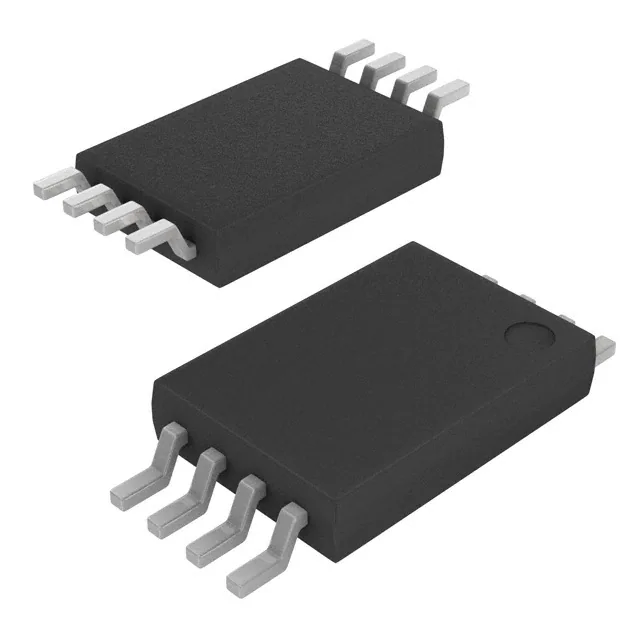
Package: 8-pin TSSOP (1 mm thin, JEDEC MO-153AA compliant), surface-mount, lead-free, RoHS-compliant.
| Pin/Terminal | Circuit Role | Design Meaning |
|---|---|---|
| VCC | Power supply input | 3 V nominal supply; must exceed 2.65 V for operation and 2.8 V for EEPROM writes. |
| ADR0 | I²C address select (LSB) | Configures 2-bit address code with ADR1; voltage thresholds defined at 0.1×, 0.33×, 0.67×, and 0.9×VCC. |
| GND | Ground reference | Common return path for analog and digital circuitry; requires low-impedance PCB connection. |
| NC | No connection | Pins 4 and 5 are unconnected internally - must remain floating or grounded per layout guidelines. |
| ADR1 | I²C address select (MSB) | Paired with ADR0 to set one of four hardware addresses (decimal 96–107); enables multi-sensor bus sharing. |
| SDA | I²C data line | Open-drain bidirectional interface; requires external pull-up (2.4–10 kΩ) and ≤100 pF total capacitance. |
| SCL | I²C clock line | Master-generated clock; supports 400 kHz max frequency; defines timing for all register reads/writes. |
Key Features
| Feature | Design Value |
|---|---|
| Ferrite-optimized temperature compensation | Factory-programmed 0.21 %/°C TCsens - maintains field accuracy across –40°C to 125°C with low-cost ferrite magnets. |
| User-programmable EEPROM space | 26 bits accessible at register 0x02 - stores calibration offsets, device IDs, or manufacturing metadata without external memory. |
| Configurable I²C addressing | Hardware (ADR0/ADR1) + EEPROM (7-bit field) - supports up to 127 devices on one bus, eliminating address conflicts in dense sensor arrays. |
| Micropower sleep command | Register-controlled entry/exit (0x20[0]) - reduces current to sub-µA while preserving register state and enabling <500 µs wake-to-accuracy recovery. |
| Integrated temperature sensor | 12-bit output (8 LSB/°C slope, 25°C = 0x000) - enables on-chip thermal derating and system-level ambient monitoring. |
Applications
| Automotive Throttle Position Sensing | Industrial BLDC Motor Commutation |
|---|---|
|
Use Scenario: Detecting angular displacement of accelerator pedal shaft using ferrite magnet mounted on rotating lever. IC Role / Device Role / Timing Role: Linear Hall sensor providing 12-bit digital position feedback via I²C to ECU microcontroller. Use Value: Factory-trimmed 4 LSB/G sensitivity and ferrite TC match eliminate need for per-unit calibration, reducing production test time and cost. |
Use Scenario: Rotor position detection in 3-phase brushless DC motors for HVAC blowers and pump drives. IC Role / Device Role / Timing Role: High-accuracy magnetic field digitizer feeding commutation logic in real-time motor control loop. Use Value: 32 kHz output refresh rate and <±3% linearity ensure precise timing of phase switching, improving torque ripple and efficiency. |
| Medical Infusion Pump Flow Monitoring | Smart Home Appliance Door Latch Detection |
|
Use Scenario: Monitoring stepper motor rotation in syringe-driven infusion pumps to verify dose delivery accuracy. IC Role / Device Role / Timing Role: Low-power Hall sensor reporting position updates over I²C during battery-operated standby and active dosing phases. Use Value: Sub-µA sleep current extends single-battery life beyond 2 years; 125°C rating supports sterilization cycle survivability. |
Use Scenario: Detecting open/closed state of refrigerator or washing machine door using embedded ferrite magnet and PCB-mounted sensor. IC Role / Device Role / Timing Role: Digital proximity detector interfacing directly with appliance MCU via shared I²C bus. Use Value: Hardware address pins (ADR0/ADR1) allow co-location with other I²C sensors (e.g., temp, humidity) without address collision or bus arbitration overhead. |
Equivalent & Alternatives
The following parts are listed as comparable options for similar linear Hall-effect sensor applications.
| Alternative Part | Technical Difference | Application Difference | Selection Advice |
|---|---|---|---|
| MLX90393ELW-ABA-000-SP | Triaxis 3D sensing, 18-bit output, SPI-only interface, no integrated EEPROM | Requires external MCU for coordinate transformation; lacks built-in sleep command and ferrite TC tuning | Select when vector field analysis or higher resolution is required; not drop-in due to different interface and packaging (16-pin TSSOP) |
| TLE493DW2B6A0HTSA1 | 3-axis Hall sensor, 12-bit I²C output, integrated wake-up interrupt, but fixed 2.8–3.5 V supply and no user EEPROM | Supports motion-triggered wake-up; however, sensitivity is fixed at 2.5 LSB/G and lacks magnet-type compensation | Prefer for motion-detection use cases needing interrupt capability; unsuitable for ferrite-based systems requiring TC matching |
Compared with MLX90393ELW-ABA-000-SP and TLE493DW2B6A0HTSA1, the A1454KLETR-4F-T uniquely combines ferrite-optimized temperature compensation, user-accessible EEPROM, and hardware-configurable I²C addressing - making it optimal for cost-sensitive, high-volume position sensing where magnet type and bus scalability are design constraints.
Availability
A1454KLETR-4F-T is available at Aetrix Electronics and suitable for automotive throttle position sensing, industrial BLDC motor commutation, medical infusion pump flow monitoring, and smart home appliance door latch detection requiring stable component supply across extended temperature ranges and long product lifecycles.
Supply support for A1454KLETR-4F-T includes scheduled delivery planning, volume procurement assistance, BOM continuity management, traceable sourcing, and lifecycle availability coordination for OEM customers, industrial embedded developers, connected-device designers, and electronics production programs.
Manufacturer
Allegro MicroSystems is a U.S.-based semiconductor company specializing in high-performance magnetic sensing and power ICs, founded in 1985 and headquartered in Manchester, NH.
The A1454 product line is designed for contactless linear position and current sensing in demanding automotive and industrial environments, emphasizing factory-trimmed accuracy, wide temperature operation, and seamless I²C integration.
FAQ
What is the factory-programmed sensitivity and magnet type for A1454KLETR-4F-T?
The A1454KLETR-4F-T is factory-programmed for 4 LSB/G sensitivity and ferrite-magnet temperature compensation (TCsens = 0.21 %/°C). This matches the thermal drift characteristics of low-cost ferrite magnets, ensuring stable field-to-digital conversion across –40°C to 125°C without external calibration. The "F" suffix in the part number explicitly denotes ferrite optimization, distinguishing it from neodymium-optimized variants like A1454KLETR-4N-T.
How does the I²C address configuration work on A1454KLETR-4F-T?
The A1454KLETR-4F-T supports dual I²C address configuration: hardware-selectable via ADR0 and ADR1 pins (yielding decimal addresses 96–107), or EEPROM-programmable for any 7-bit value (0–127). Address pins accept four voltage thresholds (0.1×, 0.33×, 0.67×, 0.9×VCC) to encode two bits. This allows up to 127 unique addresses on one bus - critical for multi-sensor systems like motor phase monitoring or HVAC zone control where multiple A1454KLETR-4F-T units share a single I²C interface.
What is the guaranteed linearity performance of A1454KLETR-4F-T over temperature?
The A1454KLETR-4F-T guarantees linearity error of <±3% over –40°C to 85°C and <±6% over –40°C to 125°C. This specification reflects worst-case deviation from ideal linear response across its ±500 G full-scale range. The error includes contributions from Hall element nonlinearity, ADC quantization, and gain/offset drift - all compensated by factory trimming. For automotive throttle applications operating within cabin temperature limits, the <±3% bound ensures reliable pedal position mapping without software correction.
Can A1454KLETR-4F-T operate from a 1.8 V I²C bus?
No - the A1454KLETR-4F-T is specified for 3 V operation only, with supply voltage range 2.65–3.5 V. Its I²C interface thresholds scale with VCC and are compatible with 3 V logic levels (VIH = 70% VCC, VIL = 30% VCC), but it does not support 1.8 V I²C buses. Allegro documentation explicitly states that 1.8 V I²C support requires special ordering (contact Allegro for availability); the standard A1454KLETR-4F-T must be used with a 3 V domain or level-shifted I²C signals.
How is sleep mode controlled and what is the wake-up latency for A1454KLETR-4F-T?
Sleep mode on A1454KLETR-4F-T is controlled exclusively via register 0x20 bit [0] (SLEEP), written over I²C. Setting this bit disables internal clocks and analog blocks, reducing current to 0.2–1 µA. Clearing the bit initiates wake-up: internal clock resumes in ~50 µs, valid output (uncompensated) appears in ~150 µs, and fully temperature-compensated output meeting accuracy specs is available within ~500 µs. No external wake signal or reset is required - the I²C master simply writes 0x00 to 0x20 to resume operation.
A1454KLETR-4F-T Specifications
- Product attributes
- Attribute value
- Manufacturer:
- Allegro MicroSystems
- Series:
- -
- Package/Case:
- 8-TSSOP (0.173", 4.40mm Width)
- Packaging:
- Tape & Reel (TR)
- Product Status:
- Active
- Technology:
- Hall Effect
- Axis:
- Single
- Output Type:
- I2C
- Sensing Range:
- -
- Voltage - Supply:
- 2.65V ~ 3.5V
- Current - Supply (Max):
- 5mA
- Current - Output (Max):
- -
- Resolution:
- -
- Bandwidth:
- 2kHz
- Operating Temperature:
- -40°C ~ 125°C
- Grade:
- -
- Qualification:
- -
- Features:
- Sleep Mode, Temperature Compensated
- Supplier Device Package:
- 8-TSSOP
- Mounting Type:
- Surface Mount
A1454KLETR-4F-T FAQ
1.How can I place an order for A1454KLETR-4F-T through Aetrix?
Please submit a Request for Quotation (RFQ) for A1454KLETR-4F-T on Aetrix. Our sales agent will provide a competitive quotation and guide you through the order confirmation once you accept the terms.
2.Are the price and stock information for A1454KLETR-4F-T reliable?
The price and inventory of A1454KLETR-4F-T are updated periodically and may fluctuate due to market conditions. Stock and pricing data are typically refreshed every 24 hours. Quotation validity for A1454KLETR-4F-T is usually 5 days.
3.What payment methods are accepted for A1454KLETR-4F-T?
We accept Wire Transfer, PayPal, Credit Card, Western Union, MoneyGram, and Escrow for A1454KLETR-4F-T transactions.
Note: Certain payment methods may incur a processing fee.
4.How is shipping managed for A1454KLETR-4F-T?
A1454KLETR-4F-T orders can be shipped via leading logistics carriers, including DHL, UPS, FedEx, TNT, or Registered Mail.
Once your A1454KLETR-4F-T order is processed, you will receive an email with the shipment details and tracking number.
Note: Tracking information may take up to 24 hours to appear. Express delivery typically takes 3–5 business days.
5.How can I obtain technical support or documentation for A1454KLETR-4F-T?
For technical support, including A1454KLETR-4F-T datasheets, pinout diagrams, or application guidance, please contact our engineering support team. They can provide detailed documentation and assistance for your A1454KLETR-4F-T requirements.
6.How does Aetrix verify that A1454KLETR-4F-T is sourced from the original manufacturer or authorized distributors?
All A1454KLETR-4F-T products on Aetrix are procured from qualified distributors and authorized channels. Our dedicated quality assurance team conducts strict verification, including traceability checks and, if necessary, third-party testing. This ensures that A1454KLETR-4F-T meets industry standards.
7.What is the process for return or replacement of A1454KLETR-4F-T?
All A1454KLETR-4F-T units undergo pre-shipment inspection (PSI). If there is an issue with A1454KLETR-4F-T, returns or replacements are accepted under the following conditions:
1.Quantity discrepancies, incorrect items, or visible external defects (such as breakage or corrosion), acknowledged by Aetrix.
2.The issue is reported within 90 days of delivery.
3.The A1454KLETR-4F-T part is unused and in its original packaging.
Return procedure for A1454KLETR-4F-T:
1.Submit a request within 90 days.
2.Obtain a Return Material Authorization (RMA) from Aetrix.
A1454KLETR-4F-T Tags
-
DRV5053VAQDBZR
Texas Instruments
-
MMC5603NJ
Memsic Inc.

-
DRV5055A1QDBZR
Texas Instruments
-
MLX90392ELQ-AAA-011-RE
Melexis Technologies NV

-
CT100LW-HS6
Allegro MicroSystems
-
DRV5056A1ELPGMQ1
Texas Instruments
-
A1304ELHLX-T
Allegro MicroSystems
-
MMC5633NJL
Memsic Inc.
-
A1308KUA-2-T
Allegro MicroSystems
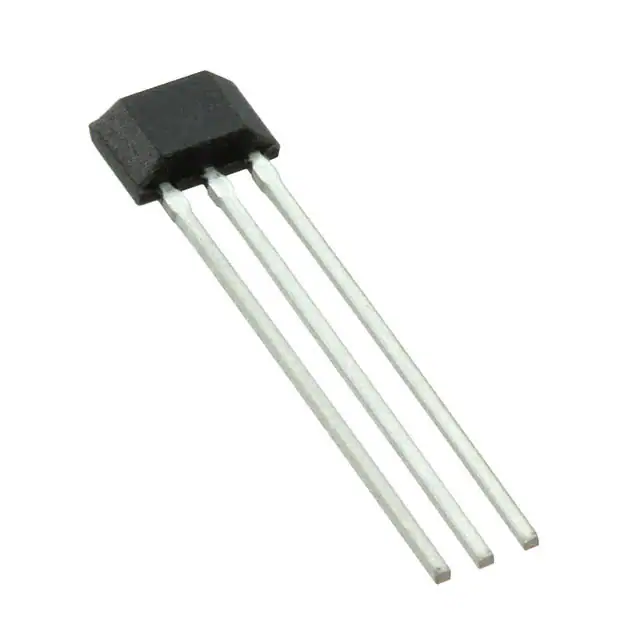
-
A1308KUA-1-T
Allegro MicroSystems
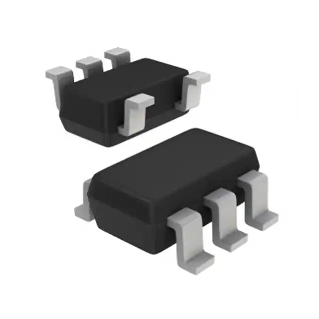
-
SI7210-B-04-IVR
Silicon Labs
-
A1308LLHLT-2-T
Allegro MicroSystems
Tech Hub

A practical engineering and sourcing framework covering lifecycle verification, lifetime-buy calculations, replacement qualification, supplier checks and counterfeit-risk controls.

TTL and CMOS logic families differ in thresholds, loading, output drive, power and timing. This engineering guide compares 74HC and 74HCT, calculates noise margins and checks 3.3 V/5 V compatibility.

A practical engineering guide to 3.3V and 5V logic compatibility, input thresholds, resistor dividers, translator ICs, MOSFET level shifting, I2C pull-ups, timing limits and power-sequencing risks.

The 74HC595 uses push-pull logic outputs, while the TPIC6B595 uses 50 V open-drain DMOS sinks for higher-power loads. This guide compares timing, current limits, 3.3 V interfacing, load wiring, thermal…

The 74HC595 converts serial data into eight stable parallel outputs. This guide covers pin functions, shift and storage timing, OE and MR behavior, drive-current limits, cascading, voltage compatibilit…

A technical comparison of level-sensitive latches and edge-triggered flip-flops, covering timing windows, setup and hold limits, master–slave operation, time borrowing, race-through, HDL inference and…

A D latch stores one bit while Enable controls when data can pass. This reference covers gate-level operation, truth tables, transparency, setup and hold timing, LE versus OE, common ICs and practical …

An SR latch stores one bit through cross-coupled feedback. This engineering reference covers NOR and NAND implementations, truth tables, forbidden-state recovery, gated operation, switch debouncing, fa…

Latch circuits retain one bit through feedback. This technical reference covers SR and D latches, truth tables, transparency, timing limits, latch-versus-flip-flop behavior, applications and common log…

An engineering guide to LED driver operation, constant-current and constant-voltage outputs, linear and switching topologies, dimming, IC selection, calculations, replacement compatibility, and fault c…


