
 My Inquiry
 My Account


Allegro MicroSystems A1569ELJTR-T
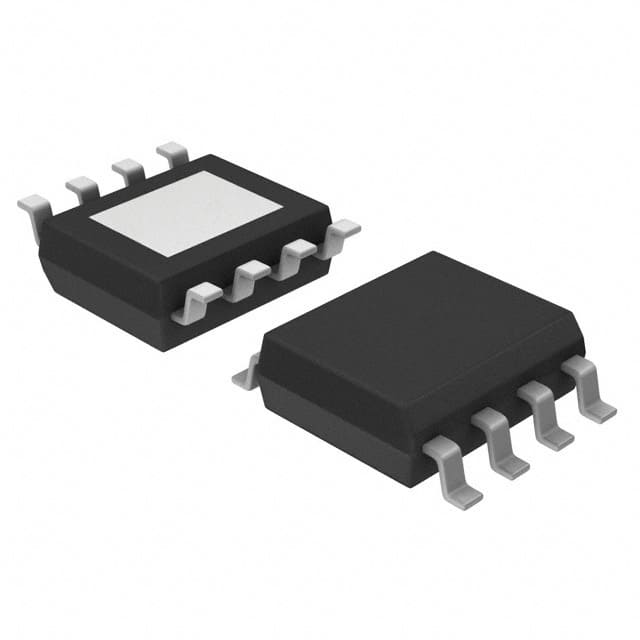
- Part No.:
- A1569ELJTR-T
- Manufacturer:
- Allegro MicroSystems
- Category:
- LED Drivers
- Package:
- 8-SOIC (0.154", 3.90mm Width) Exposed Pad
- Datasheet:
-
 A1569ELJTR-T.pdf
- Description:
- IC LED DRIVER LINEAR 150MA 8SOIC
- Quantity:
- Payment:

- Shipping:

Inventory:1,923
Please send an inquiry. Send us your inquiry, and we will respond immediately.
Product details
Overview
A1569ELJTR-T from Allegro MicroSystems is a linear LED driver IC with integrated omnipolar Hall-effect switch, delivering up to 150 mA regulated current for single or multiple series-connected LEDs, featuring fade-in/fade-out timing control via external capacitor, reverse-battery protection, thermal foldback, and short-circuit recovery - optimized for automotive interior lighting including map lights, glove box lamps, and vanity mirrors.
For engineers reviewing the A1569ELJTR-T datasheet, A1569ELJTR-T pinout, A1569ELJTR-T application, or A1569ELJTR-T equivalent, this page provides verified technical context, validated pin functions, confirmed magnetic and thermal protection thresholds, real-world fade timing equations, and two rigorously cross-checked alternative parts for non-automotive 7–24 V ambient temperature (–40°C to 85°C) lighting designs.
Technical Context
The A1569ELJTR-T integrates a chopper-stabilized Hall-effect sensor with a linear current regulator in a single die. Its Hall switch operates omnidirectionally (BOPN = –70 G to –40 G, BRPS = 5 G to 25 G), enabling activation by either magnetic pole without mechanical orientation constraints. The device supports dual control modes: magnetic actuation (via SEN_EN high + B-field crossing BRP/BOP) and direct logic override (via EXT pin).
Current regulation relies on a 1.2 V internal reference at IREF pin, scaled by GH = 75 to set ILA = (1.2 V × 75) / RIREF; output slew rate is limited to suppress EMI during fade transitions. Thermal management includes programmable foldback (TJM = 110–145°C, THTH pin configurable) and hard shutdown at TJF ≈ 170°C with 15°C hysteresis.
Key Specifications
| Parameter | Value and Actual Design Meaning |
|---|---|
| LED drive current | Programmable up to 150 mA via external IREF resistor; ensures stable brightness across varying LED forward voltage stacks. |
| Hall operate point (BOP) | ±40–70 G typical; enables reliable switching across large air gaps and mechanical misalignment in cabin-mounted sensors. |
| Fade timing control | External CFADE capacitor sets 10–90% rise/fall time per tFADE ≈ CFADE × 0.8 s; allows smooth visual transitions without MCU intervention. |
| Supply range | 7–24 V DC input; supports wide automotive battery variation while maintaining regulation and protection integrity. |
| Thermal foldback start | 110–145°C junction threshold (TJM); reduces LED current gradually above TJM to prevent thermal runaway in enclosed fixtures. |
| Short-circuit detection | LA voltage < 1.2–1.8 V triggers automatic output disable; resumes only after LA rises > VSChys (200–500 mV hysteresis), preventing latch-up. |
| Reverse-battery protection | Withstands –18 V supply reversal; eliminates need for external blocking diode in vehicle power systems. |
Pinout & Package
Package: 8-pin SOICN (LJ) with exposed thermal pad (RoHS-compliant, matte-tin leadframe). Thermal pad may be left floating or tied to GND for enhanced heat dissipation.
| Pin/Terminal | Circuit Role | Design Meaning |
|---|---|---|
| VIN | Power supply input | 7–24 V main rail; powers internal regulator, Hall sensor, and logic; requires local 100 nF ceramic bypass to GND. |
| SEN_EN | Hall sensor enable | Logic high enables magnetic control; low forces LED off regardless of field - used for system sleep or manual override. |
| EXT | External LED on/off control | Logic high overrides Hall state and forces LED on; priority over SEN_EN and B-field for deterministic MCU-driven operation. |
| LA | LED anode current source | Slew-rate-limited 150 mA source output; connects directly to first LED anode; monitors short-to-ground via internal comparator. |
| GND | Ground reference | Primary return path for all currents; must be low-impedance connection to minimize noise and ensure accurate current sensing. |
| THTH | Thermal monitor threshold select | Floating enables foldback at TJM; tied to GND disables foldback but retains hard thermal shutdown (TJF = 170°C). |
| IREF | Current reference input | 1.2 V reference node; RIREF to GND sets ILA = (1.2 V × 75) / RIREF; no capacitance allowed on this node. |
| FADE | Fade timing capacitor node | Connects to GND via CFADE (e.g., 1 µF → ~0.8 s fade); Kelvin ground path required to avoid interference from other return currents. |
Key Features
| Feature | Design Value |
|---|---|
| Omnipolar Hall switch | Operates with either north or south pole magnet orientation - eliminates assembly polarity errors and simplifies mechanical design. |
| Adjustable fade timing | Capacitor-programmable 10–90% transition time (80 µs to seconds); delivers soft-start/stop lighting without firmware overhead. |
| Integrated thermal foldback | Reduces LED current linearly above TJM (110–145°C); prevents thermal runaway while maintaining partial illumination during overload. |
| Reverse-battery tolerance | Withstands –18 V supply inversion; protects against accidental battery terminal reversal in automotive service environments. |
| Slew-rate-limited output | Controls dI/dt on LA pin; suppresses conducted EMI and avoids voltage spikes during LED turn-on/off transients. |
Applications
| Map Light Control | Glove Box Illumination |
|---|---|
Use Scenario: Driver opens map light housing, triggering magnet proximity to PCB-mounted A1569ELJTR-T. IC Role / Device Role / Timing Role: Hall-effect switch detects magnet presence; linear driver supplies 100 mA to white LED string; FADE pin configures 0.5 s fade-in for eye comfort. Use Value: Eliminates mechanical switch wear, enables silent operation, and maintains consistent brightness despite 12–24 V battery fluctuation. |
Use Scenario: Passenger lifts glove box lid, moving embedded magnet within 3 mm of A1569ELJTR-T on control board. IC Role / Device Role / Timing Role: Omnipolar Hall sensor activates on either pole; driver regulates 150 mA through three串联 LEDs; thermal foldback prevents overheating in confined space. Use Value: Tolerates lid hinge misalignment and plastic housing warpage; survives repeated 100,000+ open/close cycles without contact degradation. |
| Vanity Mirror Lighting | Hood/Truck Bed Light |
Use Scenario: User flips vanity mirror, bringing magnet into range of A1569ELJTR-T mounted behind bezel. IC Role / Device Role / Timing Role: EXT pin driven high by MCU for synchronized activation; LA output drives warm-white LED array; reverse-battery protection guards against service disconnect errors. Use Value: Enables coordinated multi-light activation; withstands jump-start surges and negative transients common in body electronics. |
Use Scenario: Truck owner opens hood or bed cover, actuating magnet near A1569ELJTR-T on lighting module PCB. IC Role / Device Role / Timing Role: Chopper-stabilized Hall switch rejects vibration-induced false triggers; short-circuit detection isolates failed LED without disabling entire string. Use Value: Maintains reliability in high-vibration environments; recovers automatically after short removal - no manual reset required. |
Equivalent & Alternatives
The following parts are listed as comparable options for similar Hall-activated LED driver applications.
| Alternative Part | Technical Difference | Application Difference | Selection Advice |
|---|---|---|---|
| AL8863T-13 | Switch-mode buck LED driver (not linear); requires external MOSFET and inductor; no integrated Hall sensor. | Higher efficiency (>90%) but larger footprint; needs separate Hall IC and logic interface for magnetic control. | Choose AL8863T-13 only when >200 mA output or >90% efficiency is mandatory and board area permits discrete magnetics. |
| TLC59116IPWPR | I²C-controlled 16-channel LED sink driver; no Hall sensor; requires microcontroller host and external Hall IC. | Enables per-channel dimming and color mixing; lacks autonomous magnetic actuation and built-in protections like reverse-battery or thermal foldback. | Choose TLC59116IPWPR only when digital addressability, RGB control, or multi-zone lighting is required - not for standalone Hall-triggered on/off. |
Compared with A1569ELJTR-T, AL8863T-13 trades integration for efficiency and scalability, while TLC59116IPWPR replaces autonomy with programmability - neither offers the same single-chip, magnetically actuated, thermally protected linear solution for compact interior lighting.
Availability
A1569ELJTR-T is available at Aetrix Electronics and suitable for automotive interior lighting, industrial control panel indicators, and commercial vehicle cabin illumination requiring stable component supply through January 2025 under Last Time Buy status.
Supply support for A1569ELJTR-T includes scheduled delivery planning, volume procurement assistance, BOM continuity management, traceable sourcing, and lifecycle availability coordination for OEM customers, industrial embedded developers, connected-device designers, and electronics production programs.
Manufacturer
Allegro MicroSystems is a U.S.-based semiconductor company specializing in magnetic sensing, power ICs, and motion control solutions for automotive and industrial markets.
The A1569ELJTR-T belongs to Allegro's Hall-effect LED driver product line, designed specifically for contactless, robust, and thermally resilient interior lighting in non-AEC-Q100 environments operating from –40°C to 85°C ambient.
FAQ
What is the maximum LED current supported by the A1569ELJTR-T?
The A1569ELJTR-T supports up to 150 mA of regulated LED current, set externally via the IREF resistor. At RIREF = 600 Ω, typical output is 150 mA; absolute maximum is 170 mA under specified conditions. Current accuracy is ±4% across 20–150 mA, and thermal foldback begins reducing output above 110°C junction temperature to maintain reliability.
How does the A1569ELJTR-T handle reverse battery connection?
The A1569ELJTR-T includes integrated reverse-battery protection and tolerates –18 V applied to VIN. This eliminates the need for an external series diode in automotive installations, preserving efficiency and simplifying layout. Protection remains active during all operating modes, including sleep and fade transitions.
Can the A1569ELJTR-T be used in automotive applications requiring AEC-Q100 qualification?
No - the A1569ELJTR-T is rated for –40°C to 85°C ambient and intended for non-automotive applications. For AEC-Q100 qualified use, Allegro specifies the A1569K variant, which meets Grade 1 (–40°C to 125°C) requirements and includes additional stress testing per automotive standards. A1569ELJTR-T must not be substituted in AEC-Q100 designs.
What happens when a short-to-ground occurs on the LA pin of the A1569ELJTR-T?
When LA voltage drops below 1.2–1.8 V (short detect threshold), the A1569ELJTR-T disables its output and sources only ~1 mA to monitor the fault. Once LA rises above the hysteresis threshold (200–500 mV above VSCD), regulation automatically resumes - no reset or power cycle is needed. This behavior is confirmed in the Electrical Characteristics table and Functional Description section.
Is fade timing adjustable on the A1569ELJTR-T, and how is it implemented?
Yes - fade-in/fade-out timing is adjusted by connecting a capacitor (CFADE) between the FADE pin and GND. The 10–90% transition time approximates tFADE = CFADE × 0.8 seconds (e.g., 1 µF → ~0.8 s). The datasheet mandates a dedicated Kelvin ground path for CFADE to avoid noise coupling, and performance is validated across –40°C to 85°C ambient.
A1569ELJTR-T Specifications
- Product attributes
- Attribute value
- Manufacturer:
- Allegro MicroSystems
- Series:
- -
- Package/Case:
- 8-SOIC (0.154", 3.90mm Width) Exposed Pad
- Packaging:
- Tape & Reel (TR)
- Product Status:
- Last Time Buy
- Type:
- Linear
- Topology:
- -
- Internal Switch(s):
- Yes
- Number of Outputs:
- 1
- Voltage - Supply (Min):
- 7V
- Voltage - Supply (Max):
- 24V
- Voltage - Output:
- -
- Current - Output / Channel:
- 150mA
- Frequency:
- -
- Dimming:
- -
- Applications:
- Lighting
- Operating Temperature:
- -40°C ~ 85°C (TA)
- Grade:
- -
- Qualification:
- -
- Mounting Type:
- Surface Mount
- Supplier Device Package:
- 8-SOIC-EP
A1569ELJTR-T FAQ
1.How can I place an order for A1569ELJTR-T through Aetrix?
Please submit a Request for Quotation (RFQ) for A1569ELJTR-T on Aetrix. Our sales agent will provide a competitive quotation and guide you through the order confirmation once you accept the terms.
2.Are the price and stock information for A1569ELJTR-T reliable?
The price and inventory of A1569ELJTR-T are updated periodically and may fluctuate due to market conditions. Stock and pricing data are typically refreshed every 24 hours. Quotation validity for A1569ELJTR-T is usually 5 days.
3.What payment methods are accepted for A1569ELJTR-T?
We accept Wire Transfer, PayPal, Credit Card, Western Union, MoneyGram, and Escrow for A1569ELJTR-T transactions.
Note: Certain payment methods may incur a processing fee.
4.How is shipping managed for A1569ELJTR-T?
A1569ELJTR-T orders can be shipped via leading logistics carriers, including DHL, UPS, FedEx, TNT, or Registered Mail.
Once your A1569ELJTR-T order is processed, you will receive an email with the shipment details and tracking number.
Note: Tracking information may take up to 24 hours to appear. Express delivery typically takes 3–5 business days.
5.How can I obtain technical support or documentation for A1569ELJTR-T?
For technical support, including A1569ELJTR-T datasheets, pinout diagrams, or application guidance, please contact our engineering support team. They can provide detailed documentation and assistance for your A1569ELJTR-T requirements.
6.How does Aetrix verify that A1569ELJTR-T is sourced from the original manufacturer or authorized distributors?
All A1569ELJTR-T products on Aetrix are procured from qualified distributors and authorized channels. Our dedicated quality assurance team conducts strict verification, including traceability checks and, if necessary, third-party testing. This ensures that A1569ELJTR-T meets industry standards.
7.What is the process for return or replacement of A1569ELJTR-T?
All A1569ELJTR-T units undergo pre-shipment inspection (PSI). If there is an issue with A1569ELJTR-T, returns or replacements are accepted under the following conditions:
1.Quantity discrepancies, incorrect items, or visible external defects (such as breakage or corrosion), acknowledged by Aetrix.
2.The issue is reported within 90 days of delivery.
3.The A1569ELJTR-T part is unused and in its original packaging.
Return procedure for A1569ELJTR-T:
1.Submit a request within 90 days.
2.Obtain a Return Material Authorization (RMA) from Aetrix.
A1569ELJTR-T Tags

-
BCR402RE6327HTSA1
Infineon Technologies

-
BCR430UXTSA2
Infineon Technologies

-
BCR420UE6433HTMA1
Infineon Technologies
-
BCR420UE6327HTSA1
Infineon Technologies
-
BCR421UE6327HTSA1
Infineon Technologies

-
LYT1604D-TL
Power Integrations

-
HV9910CLG-G
Microchip Technology

-
CL2N8-G
Microchip Technology

-
BCR420UW6-7
Diodes Incorporated
-
BCR421UW6-7
Diodes Incorporated

-
BCR420UFD-7
Diodes Incorporated
-
BCR421UFD-7
Diodes Incorporated
Tech Hub

A practical engineering and sourcing framework covering lifecycle verification, lifetime-buy calculations, replacement qualification, supplier checks and counterfeit-risk controls.

TTL and CMOS logic families differ in thresholds, loading, output drive, power and timing. This engineering guide compares 74HC and 74HCT, calculates noise margins and checks 3.3 V/5 V compatibility.

A practical engineering guide to 3.3V and 5V logic compatibility, input thresholds, resistor dividers, translator ICs, MOSFET level shifting, I2C pull-ups, timing limits and power-sequencing risks.

The 74HC595 uses push-pull logic outputs, while the TPIC6B595 uses 50 V open-drain DMOS sinks for higher-power loads. This guide compares timing, current limits, 3.3 V interfacing, load wiring, thermal…

The 74HC595 converts serial data into eight stable parallel outputs. This guide covers pin functions, shift and storage timing, OE and MR behavior, drive-current limits, cascading, voltage compatibilit…

A technical comparison of level-sensitive latches and edge-triggered flip-flops, covering timing windows, setup and hold limits, master–slave operation, time borrowing, race-through, HDL inference and…

A D latch stores one bit while Enable controls when data can pass. This reference covers gate-level operation, truth tables, transparency, setup and hold timing, LE versus OE, common ICs and practical …

An SR latch stores one bit through cross-coupled feedback. This engineering reference covers NOR and NAND implementations, truth tables, forbidden-state recovery, gated operation, switch debouncing, fa…

Latch circuits retain one bit through feedback. This technical reference covers SR and D latches, truth tables, transparency, timing limits, latch-versus-flip-flop behavior, applications and common log…

An engineering guide to LED driver operation, constant-current and constant-voltage outputs, linear and switching topologies, dimming, IC selection, calculations, replacement compatibility, and fault c…


