
 My Inquiry
 My Account


Allegro MicroSystems A3903EEETR-T
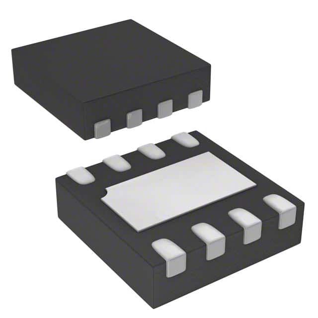
- Part No.:
- A3903EEETR-T
- Manufacturer:
- Allegro MicroSystems
- Category:
- Motor Drivers, Controllers
- Package:
- 8-UFDFN Exposed Pad
- Datasheet:
-
 A3903EEETR-T.pdf
- Description:
- IC MOTOR DRIVER 3V-5.5V 8DFN
- Quantity:
- Payment:

- Shipping:

Inventory:1,100
Please send an inquiry. Send us your inquiry, and we will respond immediately.
Product details
Overview
A3903EEETR-T from Allegro MicroSystems is a discontinued low-voltage bidirectional DC motor driver IC in an 8-lead DFN package, delivering up to 500 mA output current with adjustable constant-voltage regulation across the motor coil. It operates from 3–5.5 V supply, supports forward/reverse/brake/standby modes via dual logic inputs, and integrates thermal shutdown, UVLO, and shoot-through protection. Used in portable printers, robotic actuators, and camera lens control.
For engineers reviewing the A3903EEETR-T datasheet, A3903EEETR-T pinout, A3903EEETR-T application, or A3903EEETR-T equivalent, key selection considerations include its regulated source-side linear operation, <500 nA standby current, 2 mm × 2 mm footprint, –40°C to +85°C operating range, and discontinuation status requiring transition planning.
Technical Context
The A3903EEETR-T implements a full-bridge output stage with source-side linear regulation to maintain precise motor coil voltage (VOUT = 4 × VREF × R2/(R1+R2)), where VREF is a 1.285 V bandgap reference. This architecture eliminates I×RDS(on) and battery voltage variation effects on motor voltage.
Control logic interprets IN1/IN2 states for four functional modes: standby (both low), forward (IN1 high, IN2 low), reverse (IN1 low, IN2 high), and high-side brake (both high). Thermal shutdown activates at 165°C with 15°C hysteresis, and undervoltage lockout triggers below 2.6 V with 120 mV hysteresis.
Key Specifications
| Parameter | Value and Actual Design Meaning |
|---|---|
| Supply Voltage Range | 3 V to 5.5 V typical; supports single-cell Li-ion or triple-AA battery systems without external regulation. |
| Output Current Rating | 500 mA peak; sufficient for small precision actuators and micro-pumps in portable equipment. |
| Standby Supply Current | <500 nA; enables multi-year battery life in always-on low-power devices like remote sensors. |
| Operating Temperature | –40°C to +85°C; qualified for industrial and consumer portable applications with ambient thermal cycling. |
| Regulated Output Accuracy | ±4% at VSET = 1.2 V (4.8 V ±0.192 V); ensures stable motor speed under varying load and supply conditions. |
| Thermal Shutdown Threshold | 165°C junction temperature; protects against latch-up during sustained overload or poor PCB thermal design. |
| UVLO Threshold | 2.6 V rising edge with 120 mV hysteresis; prevents erratic operation during brown-out or battery depletion. |
Pinout & Package
The A3903EEETR-T is housed in an 8-lead, 2 mm × 2 mm, 0.55 mm nominal height DFN package with exposed thermal pad (suffix EE), RoHS-compliant and lead-free.
| Pin/Terminal | Circuit Role | Design Meaning |
|---|---|---|
| 1 (OUTB) | Motor terminal B | Low-side output connection to one end of DC motor coil; complements OUTA in H-bridge configuration. |
| 2 (GND) | Ground reference | Primary power and signal return path; must connect directly to thermal pad for optimal heat dissipation. |
| 3 (VDD) | Input supply | 3–5.5 V power input; requires local 10 µF bulk + 0.1 µF ceramic decoupling per layout guidelines. |
| 4 (OUTA) | Motor terminal A | High-side output connection to opposite end of DC motor coil; driven in linear mode for voltage regulation. |
| 5 (VSET) | Voltage setpoint input | Analog input setting regulated motor voltage via external resistor divider; determines VOUT = 4 × VREF × R2/(R1+R2). |
| 6 (VREF) | Bandgap reference output | 1.285 V ±40 mV reference for internal regulation; may be used externally to bias VSET divider. |
| 7 (IN1) | Logic control input 1 | Digital input controlling bridge state; high/low combination with IN2 selects forward, reverse, brake, or standby. |
| 8 (IN2) | Logic control input 2 | Digital input paired with IN1; no internal pull-ups/pull-downs-requires external biasing in floating scenarios. |
Key Features
| Feature | Design Value |
|---|---|
| Adjustable constant-voltage regulation | Enables precise motor speed control independent of battery discharge or MOSFET RDS(on) drift over temperature. |
| Source-side linear operation | Eliminates motor voltage error caused by sink-side conduction losses, improving torque consistency in low-RPM applications. |
| High-side brake mode | Provides rapid motor stopping by shorting both terminals through source drivers-requires external current limiting to avoid exceeding 500 mA peak. |
| Ultra-low standby current | Reduces quiescent drain to <500 nA, critical for battery-powered devices requiring multi-month shelf life or sleep-wake cycles. |
| Integrated protection suite | Combines thermal shutdown, UVLO, and shoot-through prevention-reduces need for external fault-handling circuitry in space-constrained designs. |
Applications
| Robotic Actuators | Portable Printers |
|---|---|
Use Scenario: Precision positioning of micro-gripper joints in battery-powered educational robots. IC Role / Device Role / Timing Role: Bidirectional motor driver regulating coil voltage to maintain consistent angular velocity across battery discharge cycle. Use Value: Eliminates speed droop during operation, enabling repeatable step accuracy without closed-loop feedback. | Use Scenario: Driving paper feed and carriage motors in handheld label printers powered by two AA cells. IC Role / Device Role / Timing Role: Low-noise H-bridge controller supporting PWM-based current control and fast direction reversal for print head movement. Use Value: Reduces audible motor whine and improves print alignment stability versus switch-mode-only drivers. |
| Camera Lens Control | Low-Noise Test Instruments |
Use Scenario: Autofocus and aperture actuation in compact digital cameras using miniature DC motors. IC Role / Device Role / Timing Role: Constant-voltage motor driver minimizing EMI during lens extension/retraction sequences. Use Value: Prevents RF coupling into image sensor analog paths, preserving SNR in high-resolution capture modes. | Use Scenario: Driving calibration actuators in portable oscilloscope front-end modules requiring sub-micron positioning. IC Role / Device Role / Timing Role: Low-quiescent, thermally stable motor interface enabling long-duration unattended calibration routines. Use Value: Maintains positional accuracy over extended test sessions without thermal drift-induced offset. |
Equivalent & Alternatives
The following parts are listed as comparable options for similar low-voltage DC motor driver applications.
| Alternative Part | Technical Difference | Application Difference | Selection Advice |
|---|---|---|---|
| A3906SESTR-T | Successor device with identical pinout, enhanced thermal performance (RθJA = 42°C/W), and extended 3–20 V input range. | Supports wider battery chemistries (e.g., 2S LiPo) and higher-power motors; retains same control logic and VSET regulation architecture. | Recommended for new designs requiring drop-in compatibility and improved power handling. |
| TB6612FNG | 2-channel H-bridge with 1.2 A per channel, fixed logic interface, no integrated voltage regulation; requires external current sensing for closed-loop control. | Better suited for higher-current applications but lacks A3903EEETR-T's constant-voltage precision and ultra-low standby current. | Consider when motor current exceeds 500 mA or when system-level voltage regulation is already implemented externally. |
Compared with A3903EEETR-T, the A3906SESTR-T offers direct replacement capability with broader voltage support and lower thermal resistance, while the TB6612FNG provides higher current capacity at the cost of regulation precision and standby efficiency-making the choice dependent on whether voltage stability or peak drive strength is the primary design constraint.
Availability
A3903EEETR-T is available at Aetrix Electronics and suitable for robotic actuators, portable printers, and camera lens control requiring stable component supply despite its discontinued status-inventory is limited and intended for legacy system support and repair.
Supply support for A3903EEETR-T includes scheduled delivery planning, volume procurement assistance, BOM continuity management, traceable sourcing, and lifecycle availability coordination for OEM customers, industrial embedded developers, connected-device designers, and electronics production programs.
Manufacturer
Allegro MicroSystems is a U.S.-based designer and manufacturer of high-performance Hall-effect sensors, motor drivers, and power ICs, founded in 1989 and headquartered in Manchester, NH.
The A3903 belongs to Allegro's low-voltage motor driver product line, engineered specifically for precision motion control in space- and power-constrained portable electronics where regulated coil voltage and nanoscale standby current are critical.
FAQ
Is the A3903EEETR-T still in production?
No, the A3903EEETR-T is a discontinued product. Allegro MicroSystems declared it End-of-Life in July 2020, and it is no longer manufactured. Aetrix Electronics holds remaining inventory for legacy support, but new designs should migrate to the recommended substitute A3906SESTR-T. The A3903EEETR-T datasheet remains publicly accessible on Allegro's website for reference and repair use.
What is the function of the VSET and VREF pins on the A3903EEETR-T?
The VREF pin outputs a stable 1.285 V bandgap reference used internally for voltage regulation. The VSET pin accepts an external voltage (typically derived from VREF via a resistor divider) to set the regulated motor coil voltage: VOUT = 4 × VREF × R2/(R1+R2). For the A3903EEETR-T, adjusting VSET between 500 mV and 1.2 V configures motor output from 2 V to 4.8 V, enabling precise speed control without closed-loop feedback.
Can the A3903EEETR-T be used in PWM motor control applications?
Yes, the A3903EEETR-T supports PWM operation in two ways: (1) external PWM applied to IN1/IN2 inputs for enable chopping (current control via duty cycle), and (2) internal voltage regulation with optional PWM override by connecting VREF directly to VSET. In enable chopping mode, the A3903EEETR-T alternates between forward/reverse and brake states to regulate average winding current-ideal for torque-controlled micro-actuators.
What thermal design considerations apply to the A3903EEETR-T?
The A3903EEETR-T requires careful thermal management due to its 49°C/W junction-to-ambient thermal resistance. Its exposed thermal pad must be soldered to a large PCB ground plane with multiple thermal vias. Layout must follow Allegro's recommended land pattern (IPC-7351 SON50P200X200X100-9M), and bulk capacitance (10 µF) plus local 0.1 µF ceramic must be placed near VDD. Without proper thermal design, the A3903EEETR-T will trigger thermal shutdown above 165°C junction temperature.
How does the A3903EEETR-T implement brake mode, and what precautions are needed?
The A3903EEETR-T enters high-side brake mode when both IN1 and IN2 are driven high, turning on both source drivers (OUTA and OUTB high) to short the motor coil through the upper switches. Unlike low-side braking, this mode lacks current limiting-peak current is only constrained by motor inductance and total RDS(on) (~1.2 Ω). To prevent damage, users must ensure motor back-EMF and supply voltage do not cause instantaneous current to exceed the A3903EEETR-T's 500 mA absolute maximum rating.
A3903EEETR-T Specifications
- Product attributes
- Attribute value
- Manufacturer:
- Allegro MicroSystems
- Series:
- -
- Package/Case:
- 8-UFDFN Exposed Pad
- Packaging:
- Tape & Reel (TR)
- Product Status:
- Obsolete
- Motor Type - Stepper:
- -
- Motor Type - AC, DC:
- Brushed DC
- Function:
- Driver - Fully Integrated, Control and Power Stage
- Output Configuration:
- Half Bridge (2)
- Interface:
- Parallel
- Technology:
- Power MOSFET
- Step Resolution:
- -
- Applications:
- General Purpose
- Current - Output:
- 500mA
- Voltage - Supply:
- 3V ~ 5.5V
- Voltage - Load:
- 3V ~ 5.5V
- Operating Temperature:
- -40°C ~ 150°C (TJ)
- Grade:
- -
- Qualification:
- -
- Mounting Type:
- Surface Mount
- Supplier Device Package:
- 8-DFN/MLP (2x2)
A3903EEETR-T FAQ
1.How can I place an order for A3903EEETR-T through Aetrix?
Please submit a Request for Quotation (RFQ) for A3903EEETR-T on Aetrix. Our sales agent will provide a competitive quotation and guide you through the order confirmation once you accept the terms.
2.Are the price and stock information for A3903EEETR-T reliable?
The price and inventory of A3903EEETR-T are updated periodically and may fluctuate due to market conditions. Stock and pricing data are typically refreshed every 24 hours. Quotation validity for A3903EEETR-T is usually 5 days.
3.What payment methods are accepted for A3903EEETR-T?
We accept Wire Transfer, PayPal, Credit Card, Western Union, MoneyGram, and Escrow for A3903EEETR-T transactions.
Note: Certain payment methods may incur a processing fee.
4.How is shipping managed for A3903EEETR-T?
A3903EEETR-T orders can be shipped via leading logistics carriers, including DHL, UPS, FedEx, TNT, or Registered Mail.
Once your A3903EEETR-T order is processed, you will receive an email with the shipment details and tracking number.
Note: Tracking information may take up to 24 hours to appear. Express delivery typically takes 3–5 business days.
5.How can I obtain technical support or documentation for A3903EEETR-T?
For technical support, including A3903EEETR-T datasheets, pinout diagrams, or application guidance, please contact our engineering support team. They can provide detailed documentation and assistance for your A3903EEETR-T requirements.
6.How does Aetrix verify that A3903EEETR-T is sourced from the original manufacturer or authorized distributors?
All A3903EEETR-T products on Aetrix are procured from qualified distributors and authorized channels. Our dedicated quality assurance team conducts strict verification, including traceability checks and, if necessary, third-party testing. This ensures that A3903EEETR-T meets industry standards.
7.What is the process for return or replacement of A3903EEETR-T?
All A3903EEETR-T units undergo pre-shipment inspection (PSI). If there is an issue with A3903EEETR-T, returns or replacements are accepted under the following conditions:
1.Quantity discrepancies, incorrect items, or visible external defects (such as breakage or corrosion), acknowledged by Aetrix.
2.The issue is reported within 90 days of delivery.
3.The A3903EEETR-T part is unused and in its original packaging.
Return procedure for A3903EEETR-T:
1.Submit a request within 90 days.
2.Obtain a Return Material Authorization (RMA) from Aetrix.
A3903EEETR-T Tags

-
DRV2603RUNR
Texas Instruments

-
DRV8837CDSGR
Texas Instruments

-
DRV8837DSGR
Texas Instruments
-
DRV8838DSGR
Texas Instruments

-
DRV8839DSSR
Texas Instruments

-
EMC2301-1-ACZL-TR
Microchip Technology
-
DRV8231ADSGR
Texas Instruments

-
EMC2302-2-AIZL-TR
Microchip Technology

-
DRV8800PWPR
Texas Instruments
-
DRV8835DSSR
Texas Instruments

-
EMC2303-1-KP-TR
Microchip Technology

-
DRV8876PWPR
Texas Instruments
Tech Hub

A practical engineering and sourcing framework covering lifecycle verification, lifetime-buy calculations, replacement qualification, supplier checks and counterfeit-risk controls.

TTL and CMOS logic families differ in thresholds, loading, output drive, power and timing. This engineering guide compares 74HC and 74HCT, calculates noise margins and checks 3.3 V/5 V compatibility.

A practical engineering guide to 3.3V and 5V logic compatibility, input thresholds, resistor dividers, translator ICs, MOSFET level shifting, I2C pull-ups, timing limits and power-sequencing risks.

The 74HC595 uses push-pull logic outputs, while the TPIC6B595 uses 50 V open-drain DMOS sinks for higher-power loads. This guide compares timing, current limits, 3.3 V interfacing, load wiring, thermal…

The 74HC595 converts serial data into eight stable parallel outputs. This guide covers pin functions, shift and storage timing, OE and MR behavior, drive-current limits, cascading, voltage compatibilit…

A technical comparison of level-sensitive latches and edge-triggered flip-flops, covering timing windows, setup and hold limits, master–slave operation, time borrowing, race-through, HDL inference and…

A D latch stores one bit while Enable controls when data can pass. This reference covers gate-level operation, truth tables, transparency, setup and hold timing, LE versus OE, common ICs and practical …

An SR latch stores one bit through cross-coupled feedback. This engineering reference covers NOR and NAND implementations, truth tables, forbidden-state recovery, gated operation, switch debouncing, fa…

Latch circuits retain one bit through feedback. This technical reference covers SR and D latches, truth tables, transparency, timing limits, latch-versus-flip-flop behavior, applications and common log…

An engineering guide to LED driver operation, constant-current and constant-voltage outputs, linear and switching topologies, dimming, IC selection, calculations, replacement compatibility, and fault c…


