
 My Inquiry
 My Account


Allegro MicroSystems A3907ECGTR
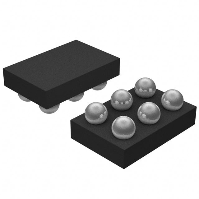
- Part No.:
- A3907ECGTR
- Manufacturer:
- Allegro MicroSystems
- Category:
- Motor Drivers, Controllers
- Package:
- 6-UFBGA, WLCSP
- Datasheet:
-
 A3907ECGTR.pdf
- Description:
- IC VOICE COIL MOTOR DVR 6WLCSP
- Quantity:
- Payment:

- Shipping:

Inventory:2,581
Please send an inquiry. Send us your inquiry, and we will respond immediately.
Product details
Overview
A3907ECGTR from Allegro MicroSystems is a low-voltage, I²C-controlled voice coil motor (VCM) driver IC designed for linear current control in compact autofocus actuators. It delivers peak output current up to 102.3 mA, operates from 2.3 V to 5.5 V, integrates a 10-bit DAC with 100 µA LSB resolution, and features thermal shutdown, UVLO, and internal flyback clamping. It is used in smartphone camera focus modules requiring precise, low-power actuator control.
For engineers reviewing the A3907ECGTR datasheet, A3907ECGTR pinout, A3907ECGTR application, or A3907ECGTR equivalent, key selection criteria include its WLCSP-6 package footprint, fixed-threshold I²C interface (VIH = 1.26 V, VIL = 0.84 V), ramp-controlled slew rate programming, sleep-mode current <500 nA, and guaranteed monotonic 10-bit DAC performance across –40°C to +85°C.
Technical Context
The A3907ECGTR implements a digitally programmable current sink using an integrated 10-bit DAC and precision current-output stage, where output current is calculated as IOUT = DAC code × 100 µA (code 1–1023). Its I²C slave address supports four options (0x18/0x1A/0x1C/0x1E), and logic thresholds are voltage-independent-fixed at ~1 V-enabling interoperability with host controllers operating at different supply voltages.
Internal protection includes undervoltage lockout (UVLOth = 2.295 V, hysteresis = 100 mV), thermal shutdown at 165°C with 15°C recovery hysteresis, and a clamp diode from IOUT to VDD. Slew rate is configurable via four timing bits (T3–T0), enabling single-step, two-step, or ramped transitions between DAC codes with step delays from 781 ns to 200 µs.
Key Specifications
| Parameter | Value and Actual Design Meaning |
|---|---|
| Output Current Range | 0 to 102.3 mA (code 0 disables output; code 1023 = full scale) |
| DAC Resolution & LSB | 10-bit, 100 µA per LSB - enables 1024 discrete current steps with ±4 LSB INL |
| Supply Voltage Range | 2.3 V to 5.5 V - compatible with Li-ion/Li-poly battery rails and low-voltage SoC I/O domains |
| I²C Interface | Standard-mode (400 kHz max), fixed VIH/VIL (1.26 V / 0.84 V), no VDD dependency - simplifies level-shifting design |
| Sleep Current | <500 nA at VDD = 2.3–3.5 V - preserves battery life during idle periods in mobile imaging systems |
| Thermal Protection | Shutdown at 165°C with 15°C hysteresis - prevents latch-up and ensures safe recovery after overtemperature events |
| Output RDS(on) | 1.45 Ω (IOUT = 102.3 mA) - determines minimum headroom: VDD − IOUT×RLOAD ≥ 350 mV for linear operation |
Pinout & Package
Package: 6-bump Wafer-Level Chip Scale Package (WLCSP), 0.8 mm × 0.8 mm, 0.4 mm pitch, bottom-side solder bumps.
| Pin/Terminal | Circuit Role | Design Meaning |
|---|---|---|
| IOUT | Sink drive output | Current-output node connected to VCM coil; includes integrated clamp diode to VDD |
| SLEEPZ | Active-low standby control | Pulling low disables all internal circuitry; input threshold VINSLP = 0.54 V (low), 1.5 V (high) |
| GND | Ground reference | Primary return path for load current and internal bias; must be low-impedance for DAC accuracy |
| SDA | I²C bidirectional data | Open-drain I/O with fixed 1 V threshold; requires external pull-up; supports read/write acknowledgment |
| VDD | Power supply input | Supplies core logic, DAC, and output stage; UVLO monitors rising edge at 2.295 V |
| SCL | I²C clock input | Asynchronous master-generated clock; timing compliant with standard-mode I²C (tLOW/tHIGH ≥ 1.3/0.6 µs) |
Key Features
| Feature | Design Value |
|---|---|
| WLCSP-6 footprint | 0.8 mm × 0.8 mm package minimizes PCB area in space-constrained camera modules |
| Configurable slew rate | Four timing bits (T3–T0) select 15 ramp profiles - prevents mechanical resonance in VCM actuation |
| Fixed I²C logic thresholds | VIH/VIL independent of VDD - eliminates need for external level shifters when interfacing with 1.8 V hosts |
| Monotonic 10-bit DAC | DNL ≤ ±1 LSB guarantees no missing codes - essential for smooth, jitter-free focus movement |
| Integrated flyback clamp | On-chip diode from IOUT to VDD suppresses inductive kickback - removes need for external protection components |
Applications
| Smartphone Camera Autofocus | Compact Digital Camera Lens Control |
|---|---|
Use Scenario: Precise linear positioning of lens elements in ultra-thin mobile phone camera modules. IC Role / Device Role / Timing Role: I²C-programmable current sink driving voice coil motor; provides closed-loop current control without external sense resistor. Use Value: 100 µA DAC resolution enables sub-micron lens positioning; low sleep current (<500 nA) extends battery runtime between focus operations. | Use Scenario: Low-power autofocus actuation in portable digital cameras with tight board space constraints. IC Role / Device Role / Timing Role: Linear VCM driver with programmable slew rate to avoid mechanical overshoot during rapid focus transitions. Use Value: Configurable ramp timing (781 ns to 200 µs per step) damps coil oscillation; WLCSP-6 footprint fits under lens barrels. |
| Medical Endoscope Focus System | AR/VR Micro-Display Actuation |
Use Scenario: Miniaturized focus mechanism in disposable or reusable endoscopic imaging probes. IC Role / Device Role / Timing Role: Low-voltage (2.3–5.5 V) VCM driver enabling direct integration with battery-powered endoscope PCBs. Use Value: UVLO and thermal shutdown ensure fail-safe behavior during sterilization or extended use; 102.3 mA output supports higher-force miniature coils. | Use Scenario: Pixel-level focus adjustment in micro-OLED or LCoS-based near-eye displays for AR glasses. IC Role / Device Role / Timing Role: High-resolution current source controlling micro-VCMs for dynamic focus tuning across eye relief distances. Use Value: ±4 LSB INL and monotonic DNL ensure repeatable, artifact-free focus sweeps; fixed I²C thresholds simplify interface to 1.2 V GPU I/O. |
Equivalent & Alternatives
The following parts are listed as comparable options for similar voice coil motor driver applications.
| Alternative Part | Technical Difference | Application Difference | Selection Advice |
|---|---|---|---|
| TI DRV2605L | Integrated haptic driver with ERM/LRA support; includes library-based waveform engine; no dedicated VCM current-sink architecture | Optimized for tactile feedback, not linear position control; lacks 100 µA DAC resolution and VCM-specific slew control | Select A3907ECGTR for pure VCM focus control; choose DRV2605L only if haptics + basic actuation sharing is required |
| ROHM BU21022KV | 8-bit DAC (256 steps), 80 mA max output, no slew rate configuration bits; smaller 1.2 mm × 1.6 mm QFN package | Limited resolution and current range reduce positioning fidelity; simpler register map but no ramp timing flexibility | A3907ECGTR preferred for high-accuracy autofocus; BU21022KV suitable for cost-sensitive, lower-performance modules |
Compared with DRV2605L and BU21022KV, the A3907ECGTR delivers superior linearity (±4 LSB INL vs. typical ±12 LSB), finer current resolution (100 µA vs. 312 µA), and dedicated VCM ramp control-making it the optimal choice for optical autofocus demanding micron-level repeatability and minimal mechanical noise.
Availability
A3907ECGTR is available at Aetrix Electronics and suitable for smartphone camera modules, medical endoscopes, and AR/VR micro-display systems requiring stable component supply, long-term manufacturability, and automotive-grade reliability screening.
Supply support for A3907ECGTR includes scheduled delivery planning, volume procurement assistance, BOM continuity management, traceable sourcing, and lifecycle availability coordination for OEM customers, industrial embedded developers, connected-device designers, and electronics production programs.
Manufacturer
Allegro MicroSystems is a U.S.-based designer and manufacturer of high-performance magnetic sensing and power IC solutions, headquartered in Worcester, Massachusetts.
The A3907 product line targets compact, battery-powered optical actuation-specifically engineered for linear voice coil motor control in mobile imaging with emphasis on low quiescent current, small footprint, and robust protection.
FAQ
What is the absolute maximum supply voltage for the A3907ECGTR?
The A3907ECGTR has an absolute maximum supply voltage (VDD) of 6 V. Operation above this rating risks permanent damage. The recommended operating range is 2.3 V to 5.5 V, and UVLO activates at 2.295 V (rising) with 100 mV hysteresis. Exceeding 6 V-even momentarily-may degrade the internal clamp diode or oxide layers. Always verify input rail stability and transient suppression in the host system before deploying the A3907ECGTR.
Does the A3907ECGTR support multiple I²C addresses, and how are they selected?
Yes, the A3907ECGTR supports four fixed I²C slave addresses: 0x18, 0x1A, 0x1C, and 0x1E. Address selection is determined by the state of two external pins (ADDR0 and ADDR1) tied to VDD or GND-though these pins are not exposed in the WLCSP-6 package of the A3907ECGTR. Instead, Allegro assigns address variants at wafer sort; the A3907ECGTR is factory-configured to one of these four addresses. Users must confirm the assigned address via device readback or datasheet revision notes prior to firmware integration.
How does the slew rate control work in the A3907ECGTR, and what timing options are available?
The A3907ECGTR uses four dedicated bits (T3–T0) in its I²C control register to configure slew rate timing. These bits define step delay intervals ranging from 781 ns to 200 µs and select between single-step, two-step, or multi-step ramp methods. For example, T3–T0 = 1100 yields 50 µs between steps in a two-step transition. This feature prevents mechanical ringing in voice coil motors by limiting di/dt-critical for silent, jitter-free autofocus. All timing values are process- and temperature-compensated per Allegro characterization.
What is the minimum output voltage headroom required for linear operation of the A3907ECGTR?
The A3907ECGTR requires ≥350 mV headroom between VDD and the IOUT node voltage to maintain linear DAC accuracy and monotonicity. This is expressed as VDD − (IOUT × RLOAD) ≥ 0.35 V. If violated, the output enters saturation, causing current droop and nonlinearity. Designers must size the VCM coil resistance and select VDD accordingly-for instance, at 102.3 mA output, RLOAD must be ≤ (VDD − 0.35 V)/0.1023 A. This constraint is explicitly verified in the A3907ECGTR's electrical characteristics table.
Can the A3907ECGTR drive bidirectional voice coil motors, or is it limited to unidirectional current sinking?
The A3907ECGTR is a unidirectional current sink only-it drives current from VDD through the VCM coil into the IOUT pin, which then sinks to GND. It cannot reverse polarity or source current. Bidirectional control requires either an H-bridge driver (e.g., A4950) or dual A3907ECGTR units with complementary coil connections. For autofocus applications-which rely on linear displacement proportional to current magnitude, not direction-the single-sink architecture is sufficient and reduces component count, PCB area, and power loss versus full-bridge solutions.
A3907ECGTR Specifications
- Product attributes
- Attribute value
- Manufacturer:
- Allegro MicroSystems
- Series:
- -
- Package/Case:
- 6-UFBGA, WLCSP
- Packaging:
- Tape & Reel (TR)
- Product Status:
- Obsolete
- Motor Type - Stepper:
- -
- Motor Type - AC, DC:
- -
- Function:
- -
- Output Configuration:
- -
- Interface:
- -
- Technology:
- -
- Step Resolution:
- -
- Applications:
- Voice Coil Motor Driver
- Current - Output:
- 102mA
- Voltage - Supply:
- 2.3V ~ 5.5V
- Voltage - Load:
- -
- Operating Temperature:
- -40°C ~ 85°C
- Grade:
- -
- Qualification:
- -
- Mounting Type:
- Surface Mount
- Supplier Device Package:
- 6-WLCSP (1.47x0.97)
A3907ECGTR FAQ
1.How can I place an order for A3907ECGTR through Aetrix?
Please submit a Request for Quotation (RFQ) for A3907ECGTR on Aetrix. Our sales agent will provide a competitive quotation and guide you through the order confirmation once you accept the terms.
2.Are the price and stock information for A3907ECGTR reliable?
The price and inventory of A3907ECGTR are updated periodically and may fluctuate due to market conditions. Stock and pricing data are typically refreshed every 24 hours. Quotation validity for A3907ECGTR is usually 5 days.
3.What payment methods are accepted for A3907ECGTR?
We accept Wire Transfer, PayPal, Credit Card, Western Union, MoneyGram, and Escrow for A3907ECGTR transactions.
Note: Certain payment methods may incur a processing fee.
4.How is shipping managed for A3907ECGTR?
A3907ECGTR orders can be shipped via leading logistics carriers, including DHL, UPS, FedEx, TNT, or Registered Mail.
Once your A3907ECGTR order is processed, you will receive an email with the shipment details and tracking number.
Note: Tracking information may take up to 24 hours to appear. Express delivery typically takes 3–5 business days.
5.How can I obtain technical support or documentation for A3907ECGTR?
For technical support, including A3907ECGTR datasheets, pinout diagrams, or application guidance, please contact our engineering support team. They can provide detailed documentation and assistance for your A3907ECGTR requirements.
6.How does Aetrix verify that A3907ECGTR is sourced from the original manufacturer or authorized distributors?
All A3907ECGTR products on Aetrix are procured from qualified distributors and authorized channels. Our dedicated quality assurance team conducts strict verification, including traceability checks and, if necessary, third-party testing. This ensures that A3907ECGTR meets industry standards.
7.What is the process for return or replacement of A3907ECGTR?
All A3907ECGTR units undergo pre-shipment inspection (PSI). If there is an issue with A3907ECGTR, returns or replacements are accepted under the following conditions:
1.Quantity discrepancies, incorrect items, or visible external defects (such as breakage or corrosion), acknowledged by Aetrix.
2.The issue is reported within 90 days of delivery.
3.The A3907ECGTR part is unused and in its original packaging.
Return procedure for A3907ECGTR:
1.Submit a request within 90 days.
2.Obtain a Return Material Authorization (RMA) from Aetrix.
A3907ECGTR Tags

-
DRV2603RUNR
Texas Instruments

-
DRV8837CDSGR
Texas Instruments

-
DRV8837DSGR
Texas Instruments
-
DRV8838DSGR
Texas Instruments

-
DRV8839DSSR
Texas Instruments

-
EMC2301-1-ACZL-TR
Microchip Technology
-
DRV8231ADSGR
Texas Instruments

-
EMC2302-2-AIZL-TR
Microchip Technology

-
DRV8800PWPR
Texas Instruments
-
DRV8835DSSR
Texas Instruments

-
EMC2303-1-KP-TR
Microchip Technology

-
DRV8876PWPR
Texas Instruments
Tech Hub

A practical engineering and sourcing framework covering lifecycle verification, lifetime-buy calculations, replacement qualification, supplier checks and counterfeit-risk controls.

TTL and CMOS logic families differ in thresholds, loading, output drive, power and timing. This engineering guide compares 74HC and 74HCT, calculates noise margins and checks 3.3 V/5 V compatibility.

A practical engineering guide to 3.3V and 5V logic compatibility, input thresholds, resistor dividers, translator ICs, MOSFET level shifting, I2C pull-ups, timing limits and power-sequencing risks.

The 74HC595 uses push-pull logic outputs, while the TPIC6B595 uses 50 V open-drain DMOS sinks for higher-power loads. This guide compares timing, current limits, 3.3 V interfacing, load wiring, thermal…

The 74HC595 converts serial data into eight stable parallel outputs. This guide covers pin functions, shift and storage timing, OE and MR behavior, drive-current limits, cascading, voltage compatibilit…

A technical comparison of level-sensitive latches and edge-triggered flip-flops, covering timing windows, setup and hold limits, master–slave operation, time borrowing, race-through, HDL inference and…

A D latch stores one bit while Enable controls when data can pass. This reference covers gate-level operation, truth tables, transparency, setup and hold timing, LE versus OE, common ICs and practical …

An SR latch stores one bit through cross-coupled feedback. This engineering reference covers NOR and NAND implementations, truth tables, forbidden-state recovery, gated operation, switch debouncing, fa…

Latch circuits retain one bit through feedback. This technical reference covers SR and D latches, truth tables, transparency, timing limits, latch-versus-flip-flop behavior, applications and common log…

An engineering guide to LED driver operation, constant-current and constant-voltage outputs, linear and switching topologies, dimming, IC selection, calculations, replacement compatibility, and fault c…


