
 My Inquiry
 My Account


Allegro MicroSystems A3932SLDTR-T
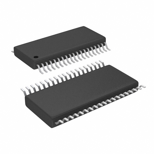
- Part No.:
- A3932SLDTR-T
- Manufacturer:
- Allegro MicroSystems
- Category:
- Motor Drivers, Controllers
- Package:
- 38-TFSOP (0.173", 4.40mm Width)
- Datasheet:
-
 A3932SLDTR-T.pdf
- Description:
- IC MOTOR DRIVER 18V-50V 38TSSOP
- Quantity:
- Payment:

- Shipping:

Inventory:1,361
Please send an inquiry. Send us your inquiry, and we will respond immediately.
Product details
Overview
A3932SLDTR-T from Allegro MicroSystems is a discontinued three-phase N-channel MOSFET controller for brushless DC motor commutation, featuring integrated 5 V reference, 13 V gate-drive regulator, synchronous rectification control, and Hall-sensor-based 120° commutation logic. It supports motor supply voltages up to 50 V, delivers ±100 mA bootstrap charge current, and implements fixed off-time PWM current limiting with user-adjustable blank time and dead time.
For engineers reviewing the A3932SLDTR-T datasheet, A3932SLDTR-T pinout, A3932SLDTR-T application, or A3932SLDTR-T equivalent, key selection considerations include its 38-pin TSSOP package, high-side/low-side gate drive timing (tr/tf ≤ 120/60 ns), thermal shutdown at 165°C, motor short-to-ground detection threshold of 2.0 V, and compatibility with external N-channel power MOSFETs in BLDC inverter stages.
Technical Context
The A3932SLDTR-T integrates Hall-input decoding logic for 120°-spaced sensors, internal fixed off-time PWM current regulation using REF/SENSE inputs, and programmable dead time via the DEAD pin with external resistor. Its high-side drivers use bootstrapped floating supplies (CA/CB/CC) charged to ~11.6 V, while low-side drivers (GLA/GLB/GLC) operate from the internal VREG rail.
Protection architecture includes undervoltage lockout on VREG (9.7 V turn-on), thermal shutdown with 10°C hysteresis, motor lead short-to-ground detection via VDSH monitoring, and bootstrap capacitor charge-current supervision. Synchronous rectification (SR input) enables active current decay paths, reducing body-diode conduction losses during PWM off-cycles.
Key Specifications
| Parameter | Value and Actual Design Meaning |
|---|---|
| Motor Supply Voltage | Up to 50 V - supports wide-range BLDC systems including industrial pumps and fans |
| Gate Drive Regulator (VREG) | 13 V typical at 10 mA - powers low-side drivers and bootstrap charging circuits |
| Bootstrap Charge Current | 100 mA - ensures rapid recharge of external bootstrap capacitors during low-side conduction |
| Current Sense Input Range | –5 V to +1.5 V - accommodates bidirectional current sensing with external shunt |
| Thermal Shutdown Threshold | 165°C junction temperature - latches fault until reset or commutation cycle clears short-to-ground |
| Dead Time Adjustment Range | 100 ns to 5.5 µs via DEAD pin resistor - prevents shoot-through in external N-MOSFET bridges |
| Logic Supply Reference (VLCAP) | 5.0 V ±2.5% - provides stable bias for HALL, MODE, DIR, BRAKE, and SR inputs |
Pinout & Package
Package: 38-pin TSSOP (suffix LD), 0.5 mm pitch, JEDEC MO-153 BD-1 compliant, thermal resistance RθJA = 51°C/W on four-layer PCB.
| Pin/Terminal | Circuit Role | Design Meaning |
|---|---|---|
| SA/SB/SC | Motor phase outputs | Direct connection points to BLDC motor windings; serve as return path for bootstrap capacitor charging |
| GHA/GHB/GHC | High-side gate drivers | Drive gates of external high-side N-MOSFETs; require external series resistors for dv/dt control |
| GLA/GLB/GLC | Low-side gate drivers | Drive gates of external low-side N-MOSFETs; sourced from VREG rail |
| CA/CB/CC | Bootstrap capacitor positive terminals | Provide floating supply for high-side drivers; voltage ≈ VREG + VSx when associated Sx is low |
| H1/H2/H3 | Hall sensor inputs | Accept 120°-spaced digital Hall signals; internally pulled up to VLCAP (5 V) |
| REF/SENSE | Current limit programming inputs | Set peak current IPEAK = VREF/RSENSE; SENSE rejects transients via programmable blank time |
| DEAD | Dead time control | Analog input setting high-side to low-side turn-off/turn-on delay; resistor to LCAP sets 100 ns–5.5 µs range |
| FAULT/TACH | Open-drain diagnostic outputs | FAULT asserts low on thermal, UVLO, Hall error, or short-to-ground; TACH pulses per Hall transition for speed feedback |
Key Features
| Feature | Design Value |
|---|---|
| Synchronous rectification control | Reduces power loss by actively switching low-side FETs during PWM off-cycle instead of relying on body diodes |
| Adjustable dead time | Prevents cross-conduction in external N-MOSFET half-bridges via external resistor on DEAD pin |
| Integrated 5 V reference (VLCAP) | Stable bias for all logic inputs; capable of sourcing ≤3 mA for DEAD, FAULT, and TACH pull-ups |
| Motor short-to-ground protection | Detects >2.0 V drain-source voltage on active high-side FETs; fault cleared each commutation unless latched |
| Selectable fast/slow current decay | MODE pin selects decay path: fast decay (both FETs off) or slow decay (only high-side off) for torque ripple control |
| Brake input (BRAKE) | Active-low signal forcing all low-side FETs on and high-side FETs off to short BEMF and dynamically brake motor |
Applications
| Industrial BLDC Fans | Automotive HVAC Blowers |
|---|---|
Use Scenario: High-reliability cooling in industrial enclosures with variable airflow demand and ambient temperatures up to 85°C. IC Role / Device Role / Timing Role: Three-phase gate driver controlling external N-MOSFET bridge; commutates based on Hall sensor feedback with fixed off-time current regulation. Use Value: Enables precise torque control via REF voltage tuning and reduces heat generation through synchronous rectification, extending system lifetime. |
Use Scenario: Cabin air circulation in passenger vehicles requiring EMI-robust motor control and thermal fault resilience. IC Role / Device Role / Timing Role: Motor controller interfacing with automotive-grade Hall sensors; implements undervoltage lockout and thermal shutdown per AEC-Q100-aligned safety margins. Use Value: Fault diagnostics (FAULT output) and short-to-ground detection support functional safety requirements without external monitoring circuitry. |
| Medical Infusion Pumps | Power Tools with Electronic Commutation |
Use Scenario: Precise, quiet, and repeatable fluid delivery in portable medical devices operating from 24 V battery packs. IC Role / Device Role / Timing Role: BLDC motor controller providing smooth sinusoidal-like commutation via trapezoidal Hall sequencing and adjustable dead time. Use Value: Low acoustic noise achieved through programmable blank time and optimized PWM frequency (22.5 kHz), avoiding audible resonance. |
Use Scenario: Cordless drill/driver applications demanding high starting torque, dynamic braking, and overcurrent protection under load variation. IC Role / Device Role / Timing Role: Gate driver managing high-current N-MOSFETs in inverter stage; uses BRAKE input for rapid deceleration and PWM input for speed modulation. Use Value: 100% duty cycle capability and robust thermal shutdown (165°C) allow sustained high-power operation without gate drive collapse. |
Equivalent & Alternatives
The following parts are listed as comparable options for similar three-phase MOSFET controller applications.
| Alternative Part | Technical Difference | Application Difference | Selection Advice |
|---|---|---|---|
| A3938SLDTR-T | Successor device with enhanced ESD rating (±4 kV HBM), lower quiescent current (5.5 mA vs. 8.0 mA), and improved bootstrap charge current (120 mA vs. 100 mA) | Designed for new designs requiring extended product lifecycle and higher reliability in noisy environments | Select A3938SLDTR-T for new designs; it is Allegro's recommended replacement with full pin and functional compatibility |
| MP6532GQ-Z | Monolithic 3-phase gate driver (no external MOSFETs required); integrates 200 V half-bridge drivers; lacks Hall commutation logic and synchronous rectification control | Targets space-constrained applications where integration outweighs flexibility; requires external position sensing | Choose MP6532GQ-Z only if board area is critical and Hall sensor interface is not needed; otherwise, A3932SLDTR-T offers superior motor control granularity |
Compared with A3932SLDTR-T, A3938SLDTR-T provides longer-term supply assurance and marginally improved gate drive performance, while MP6532GQ-Z trades external MOSFET flexibility for compactness and eliminates Hall interface - making it unsuitable for direct drop-in replacement but viable for simplified BLDC topologies.
Availability
A3932SLDTR-T is available at Aetrix Electronics and suitable for industrial BLDC fans, automotive HVAC blowers, medical infusion pumps, and power tools requiring stable component supply despite end-of-life status.
Supply support for A3932SLDTR-T includes scheduled delivery planning, volume procurement assistance, BOM continuity management, traceable sourcing, and lifecycle availability coordination for OEM customers, industrial embedded developers, connected-device designers, and electronics production programs.
Manufacturer
Allegro MicroSystems is a U.S.-based designer of high-performance magnetic sensing and power IC solutions, headquartered in Worcester, Massachusetts, with global manufacturing and support infrastructure.
The A3932 product line was developed specifically for cost-sensitive, high-efficiency three-phase BLDC motor control in industrial and automotive subsystems, emphasizing robust gate drive, integrated protection, and Hall-based commutation without microcontroller dependency.
FAQ
Is A3932SLDTR-T still in production?
No, A3932SLDTR-T is a discontinued product. Allegro MicroSystems ceased production as of June 1, 2016, and no new samples or production lots are available. A3932SLDTR-T remains supported for legacy repair and maintenance, but new designs should migrate to A3938SLDTR-T per Allegro's official recommendation.
What is the maximum motor supply voltage supported by A3932SLDTR-T?
The A3932SLDTR-T supports motor supply voltages up to 50 V, as specified in its Absolute Maximum Ratings. Operation above this level risks permanent damage to internal regulators and gate drivers. For 12 V systems, VBB must be shorted to VREG while respecting the 15 V absolute maximum on VREG, including transients.
How does the synchronous rectification feature work in A3932SLDTR-T?
In A3932SLDTR-T, synchronous rectification is enabled by pulling the SR pin high. During PWM off-cycles, the controller actively switches appropriate high-side and low-side gate drivers to route recirculating current through MOSFET channels instead of body diodes - reducing conduction loss and eliminating need for external clamp diodes.
Can A3932SLDTR-T drive P-channel high-side MOSFETs?
No, A3932SLDTR-T is designed exclusively for N-channel high-side and low-side MOSFETs. Its GHA/GHB/GHC outputs provide bootstrapped positive gate drive relative to SA/SB/SC, and GLA/GLB/GLC outputs source current from VREG - both architectures assume N-MOSFET configuration with source-connected motor phases.
What happens when the FAULT pin goes low on A3932SLDTR-T?
When the FAULT pin on A3932SLDTR-T asserts low (open-drain), it indicates one or more active faults: invalid Hall code (000 or 111), VREG undervoltage (<9.1 V), thermal shutdown (>165°C), or motor lead short-to-ground. Except for short-to-ground (cleared per commutation), all faults force coast mode - turning off all gate drivers until RESET is toggled or power cycled.
A3932SLDTR-T Specifications
- Product attributes
- Attribute value
- Manufacturer:
- Allegro MicroSystems
- Series:
- -
- Package/Case:
- 38-TFSOP (0.173", 4.40mm Width)
- Packaging:
- Tape & Reel (TR)
- Product Status:
- Obsolete
- Motor Type - Stepper:
- -
- Motor Type - AC, DC:
- Brushless DC (BLDC)
- Function:
- Controller - Commutation, Direction Management
- Output Configuration:
- Pre-Driver - Half Bridge (3)
- Interface:
- Parallel, PWM
- Technology:
- Power MOSFET
- Step Resolution:
- -
- Applications:
- General Purpose
- Current - Output:
- -
- Voltage - Supply:
- 18V ~ 50V
- Voltage - Load:
- -
- Operating Temperature:
- -20°C ~ 85°C (TA)
- Grade:
- -
- Qualification:
- -
- Mounting Type:
- Surface Mount
- Supplier Device Package:
- 38-TSSOP
A3932SLDTR-T FAQ
1.How can I place an order for A3932SLDTR-T through Aetrix?
Please submit a Request for Quotation (RFQ) for A3932SLDTR-T on Aetrix. Our sales agent will provide a competitive quotation and guide you through the order confirmation once you accept the terms.
2.Are the price and stock information for A3932SLDTR-T reliable?
The price and inventory of A3932SLDTR-T are updated periodically and may fluctuate due to market conditions. Stock and pricing data are typically refreshed every 24 hours. Quotation validity for A3932SLDTR-T is usually 5 days.
3.What payment methods are accepted for A3932SLDTR-T?
We accept Wire Transfer, PayPal, Credit Card, Western Union, MoneyGram, and Escrow for A3932SLDTR-T transactions.
Note: Certain payment methods may incur a processing fee.
4.How is shipping managed for A3932SLDTR-T?
A3932SLDTR-T orders can be shipped via leading logistics carriers, including DHL, UPS, FedEx, TNT, or Registered Mail.
Once your A3932SLDTR-T order is processed, you will receive an email with the shipment details and tracking number.
Note: Tracking information may take up to 24 hours to appear. Express delivery typically takes 3–5 business days.
5.How can I obtain technical support or documentation for A3932SLDTR-T?
For technical support, including A3932SLDTR-T datasheets, pinout diagrams, or application guidance, please contact our engineering support team. They can provide detailed documentation and assistance for your A3932SLDTR-T requirements.
6.How does Aetrix verify that A3932SLDTR-T is sourced from the original manufacturer or authorized distributors?
All A3932SLDTR-T products on Aetrix are procured from qualified distributors and authorized channels. Our dedicated quality assurance team conducts strict verification, including traceability checks and, if necessary, third-party testing. This ensures that A3932SLDTR-T meets industry standards.
7.What is the process for return or replacement of A3932SLDTR-T?
All A3932SLDTR-T units undergo pre-shipment inspection (PSI). If there is an issue with A3932SLDTR-T, returns or replacements are accepted under the following conditions:
1.Quantity discrepancies, incorrect items, or visible external defects (such as breakage or corrosion), acknowledged by Aetrix.
2.The issue is reported within 90 days of delivery.
3.The A3932SLDTR-T part is unused and in its original packaging.
Return procedure for A3932SLDTR-T:
1.Submit a request within 90 days.
2.Obtain a Return Material Authorization (RMA) from Aetrix.
A3932SLDTR-T Tags

-
DRV2603RUNR
Texas Instruments

-
DRV8837CDSGR
Texas Instruments

-
DRV8837DSGR
Texas Instruments
-
DRV8838DSGR
Texas Instruments

-
DRV8839DSSR
Texas Instruments

-
EMC2301-1-ACZL-TR
Microchip Technology
-
DRV8231ADSGR
Texas Instruments

-
EMC2302-2-AIZL-TR
Microchip Technology

-
DRV8800PWPR
Texas Instruments
-
DRV8835DSSR
Texas Instruments

-
EMC2303-1-KP-TR
Microchip Technology

-
DRV8876PWPR
Texas Instruments
Tech Hub

A practical engineering and sourcing framework covering lifecycle verification, lifetime-buy calculations, replacement qualification, supplier checks and counterfeit-risk controls.

TTL and CMOS logic families differ in thresholds, loading, output drive, power and timing. This engineering guide compares 74HC and 74HCT, calculates noise margins and checks 3.3 V/5 V compatibility.

A practical engineering guide to 3.3V and 5V logic compatibility, input thresholds, resistor dividers, translator ICs, MOSFET level shifting, I2C pull-ups, timing limits and power-sequencing risks.

The 74HC595 uses push-pull logic outputs, while the TPIC6B595 uses 50 V open-drain DMOS sinks for higher-power loads. This guide compares timing, current limits, 3.3 V interfacing, load wiring, thermal…

The 74HC595 converts serial data into eight stable parallel outputs. This guide covers pin functions, shift and storage timing, OE and MR behavior, drive-current limits, cascading, voltage compatibilit…

A technical comparison of level-sensitive latches and edge-triggered flip-flops, covering timing windows, setup and hold limits, master–slave operation, time borrowing, race-through, HDL inference and…

A D latch stores one bit while Enable controls when data can pass. This reference covers gate-level operation, truth tables, transparency, setup and hold timing, LE versus OE, common ICs and practical …

An SR latch stores one bit through cross-coupled feedback. This engineering reference covers NOR and NAND implementations, truth tables, forbidden-state recovery, gated operation, switch debouncing, fa…

Latch circuits retain one bit through feedback. This technical reference covers SR and D latches, truth tables, transparency, timing limits, latch-versus-flip-flop behavior, applications and common log…

An engineering guide to LED driver operation, constant-current and constant-voltage outputs, linear and switching topologies, dimming, IC selection, calculations, replacement compatibility, and fault c…


