
 My Inquiry
 My Account


Allegro MicroSystems A3949SLPTR-T
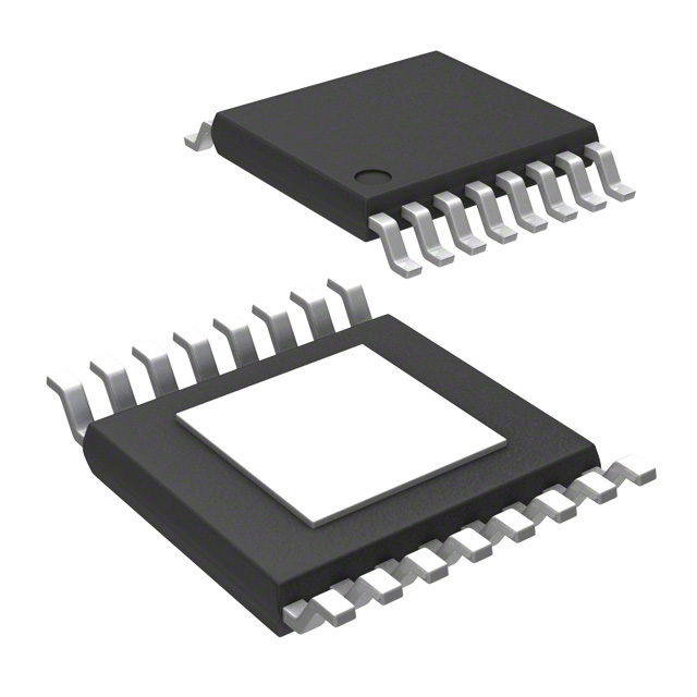
- Part No.:
- A3949SLPTR-T
- Manufacturer:
- Allegro MicroSystems
- Category:
- Motor Drivers, Controllers
- Package:
- 16-TSSOP (0.173", 4.40mm Width) Exposed Pad
- Datasheet:
-
 A3949SLPTR-T.pdf
- Description:
- IC MOTOR DRIVER 8V-36V 16TSSOP
- Quantity:
- Payment:

- Shipping:

Inventory:2,683
Please send an inquiry. Send us your inquiry, and we will respond immediately.
Product details
Overview
A3949SLPTR-T from Allegro MicroSystems is a DMOS full-bridge motor driver IC designed for PWM-controlled DC motors, delivering ±2.8 A peak output current at up to 36 V supply voltage, with PHASE/ENABLE control interface and internal synchronous rectification for reduced power loss in industrial actuators and automotive seat/mirror systems.
For engineers reviewing the A3949SLPTR-T datasheet, A3949SLPTR-T pinout, A3949SLPTR-T application, or A3949SLPTR-T equivalent, key selection criteria include thermal shutdown (170°C), UVLO (6 V with 250 mV hysteresis), low RDS(ON) (0.3–0.48 Ω), sleep mode current (≤10 μA), and LB-package SOIC-16 copper batwing thermal performance.
Technical Context
The A3949SLPTR-T implements a four-MOSFET full-bridge topology with independent source/sink drivers, charge pump (CP1/CP2) for high-side gate drive, and VREG-regulated low-side gate supply. It supports forward/reverse/brake/fast-decay SR modes via MODE, PHASE, ENABLE, and SLEEP logic inputs.
Protection architecture includes crossover current detection, thermal shutdown with 15°C hysteresis, and dual undervoltage lockout monitoring on both VBB (6 V threshold) and VCP (reservoir capacitor voltage), ensuring safe operation under brownout or charge-pump failure conditions.
Key Specifications
| Parameter | Value and Actual Design Meaning |
|---|---|
| Peak Output Current | ±2.8 A - supports medium-power DC motors without external heatsinking in 2-layer PCB layouts |
| Supply Voltage Range | 8–36 V - compatible with 12 V and 24 V industrial and automotive battery rails |
| RDS(ON) (Sink/Source) | 0.3–0.48 Ω @ 25°C - limits conduction loss to ≤2.4 W per channel at 2.8 A |
| UVLO Threshold | 6 V with 250 mV hysteresis - prevents erratic switching during startup or battery sag |
| Thermal Shutdown | 170°C junction temperature with 15°C hysteresis - enables automatic recovery after cooling |
| Sleep Mode Current | ≤10 μA - reduces system standby power in battery-powered portable devices |
| Propagation Delay | 100–600 ns - ensures precise PWM timing alignment for closed-loop motor control |
Pinout & Package
The A3949SLPTR-T is housed in a 16-pin SOICW package (suffix LB) with exposed copper batwing thermal tab, lead-free construction, and internally fused pins 4 (SLEEP) and 13 (VCP).
| Pin/Terminal | Circuit Role | Design Meaning |
|---|---|---|
| 1, 15 | N/C | No internal connection; must be left unconnected |
| 2 | MODE | Selects decay mode (slow/fast) and braking behavior via logic level |
| 3, 12 | GND | Power ground return paths; both pins required for low-impedance layout |
| 4 | SLEEP | Active-high input enabling ultra-low-power sleep state (≤10 μA IBB) |
| 5 | ENABLE | Global PWM enable/disable; drives outputs to Hi-Z when low |
| 6, 9 | OUTA / OUTB | Full-bridge output terminals; connect directly to motor terminals |
| 7 | SENSE | Current-sense return path; used with external sense resistor for overcurrent protection |
| 8 | VBB | Main motor supply input (8–36 V); requires ≥100 μF bulk capacitance |
| 10, 11 | CP1 / CP2 | Charge pump oscillator nodes; require 0.1 μF ceramic capacitors for high-side gate drive |
| 13 | VCP | Charge pump reservoir node; monitored for UVLO; decouple with 0.1 μF to VBB |
| 14 | VREG | Internally regulated low-side gate supply; decouple with 0.22 μF to GND |
Key Features
| Feature | Design Value |
|---|---|
| Synchronous Rectification | Reduces power dissipation during PWM off-time by actively turning on low-side FETs instead of relying on body diodes |
| Internal Charge Pump | Generates gate drive voltage >VBB for high-side DMOS switches, eliminating need for external bootstrap circuitry |
| Crossover Current Protection | Detects shoot-through risk during switching transitions and forces dead time to prevent simultaneous high-/low-side conduction |
| Thermal Shutdown with Hysteresis | Shuts down at 170°C and re-enables only after cooling by ≥15°C, preventing thermal oscillation in marginally heatsunk designs |
| Logic-Compatible Inputs | PHASE/ENABLE/MODE/SLEEP accept standard 3.3 V or 5 V CMOS/TTL levels without external level-shifting |
Applications
| Automotive Power Seats | Industrial Linear Actuators |
|---|---|
Use Scenario: Bidirectional positioning of vehicle seat fore/aft and recline mechanisms using 12 V DC motors. IC Role / Device Role / Timing Role: Full-bridge driver executing PHASE/ENABLE-based direction and speed control with fast-decay SR for smooth stop response. Use Value: Enables compact ECU design with integrated protection (UVLO, thermal shutdown) and <10 μA sleep current for ignition-off power budget compliance. | Use Scenario: Precision extension/retraction of factory automation linear slides driven by 24 V brushed DC motors. IC Role / Device Role / Timing Role: Motor interface translating PLC PWM commands into bidirectional torque delivery with synchronous rectification for efficiency. Use Value: Delivers ±2.8 A peak current with 0.3 Ω sink RDS(ON), reducing heat generation and enabling convection-cooled enclosure designs. |
| Medical Infusion Pumps | Consumer Robotics Platforms |
Use Scenario: Controlled syringe advancement in battery-powered portable infusion devices requiring silent, low-ripple motion. IC Role / Device Role / Timing Role: Low-noise PWM motor controller implementing slow-decay braking to minimize mechanical vibration and audible coil whine. Use Value: Sleep mode (≤10 μA) extends single-charge battery life; internal UVLO prevents motor stall during low-battery conditions. | Use Scenario: Drive wheels and articulated joints in educational and hobbyist robots powered by 2-cell Li-ion (7.4 V) or 6-cell NiMH (8.4 V) packs. IC Role / Device Role / Timing Role: Compact full-bridge interface between microcontroller GPIOs and brushed DC gearmotors, supporting forward/reverse/brake states. Use Value: SOIC-16 LB package provides robust thermal performance without heatsinks; pin-compatible control logic simplifies firmware reuse across platforms. |
Equivalent & Alternatives
The following parts are listed as comparable options for similar full-bridge motor driver applications.
| Alternative Part | Technical Difference | Application Difference | Selection Advice |
|---|---|---|---|
| A3950SLPTR-T | Higher RDS(ON) (0.55 Ω typ.), same 16-pin LB package, identical pinout and control logic | Lower efficiency at high current; suitable where thermal margin exists but cost sensitivity is higher | Select A3950SLPTR-T only if peak load current remains below 2.0 A and board-level thermal design accommodates +1.2 W extra dissipation |
| TB6612FNG | 2-channel H-bridge (dual independent bridges), lower voltage rating (15 V max), no internal charge pump | Requires external bootstrap or high-side driver; better suited for dual-motor or low-voltage (<12 V) applications | Choose TB6612FNG when driving two separate small motors or when VBB < 12 V; not drop-in for A3949SLPTR-T due to different voltage and topology |
Compared with A3949SLPTR-T, the A3950SLPTR-T offers identical footprint and control interface but trades efficiency for cost, while the TB6612FNG provides dual-bridge flexibility at the expense of voltage capability and integrated high-side drive-neither is pin-compatible, requiring PCB redesign for substitution.
Availability
A3949SLPTR-T is available at Aetrix Electronics and suitable for automotive power seats, industrial linear actuators, medical infusion pumps, and consumer robotics platforms requiring stable component supply despite end-of-life status.
Supply support for A3949SLPTR-T includes scheduled delivery planning, volume procurement assistance, BOM continuity management, traceable sourcing, and lifecycle availability coordination for OEM customers, industrial embedded developers, connected-device designers, and electronics production programs.
Manufacturer
Allegro MicroSystems is a U.S.-based designer and manufacturer of high-performance magnetic sensing and power IC solutions, headquartered in Worcester, Massachusetts.
The A3949 product line targets cost-sensitive, thermally constrained brushed DC motor control in automotive comfort systems and industrial motion applications, emphasizing integration of protection, efficiency, and compact packaging.
FAQ
Is the A3949SLPTR-T still in production?
No, the A3949SLPTR-T is a discontinued product as of June 2, 2014. Allegro MicroSystems no longer manufactures or supplies new units. Aetrix Electronics maintains limited legacy stock for existing design continuity, but the A3949SLPTR-T should not be selected for new designs. Customers are advised to evaluate the A3950SLPTR-T or other modern alternatives for new projects.
What is the function of the SLEEP pin on the A3949SLPTR-T?
The SLEEP pin on the A3949SLPTR-T is an active-high logic input that disables internal circuitry-including the charge pump, VREG regulator, and gate drivers-to reduce quiescent current to ≤10 μA. When pulled low, the A3949SLPTR-T enters sleep mode; a 1 ms stabilization delay is required after returning SLEEP high before applying PWM signals to allow the charge pump to recharge.
Can the A3949SLPTR-T drive a 36 V motor continuously?
The A3949SLPTR-T supports VBB up to 36 V DC, but continuous operation at this voltage depends on thermal management. With its RDS(ON) of 0.3–0.48 Ω and 52°C/W junction-to-ambient thermal resistance (2-layer PCB), sustained 2.8 A output at 36 V exceeds safe power dissipation limits. For reliable 36 V use, derate current to ≤1.5 A or implement enhanced heatsinking per Allegro's LB package layout guidelines.
How does the A3949SLPTR-T implement braking?
The A3949SLPTR-T supports two braking modes: slow decay (via MODE = high + ENABLE = low) shorts motor terminals through both low-side FETs, while fast-decay synchronous rectification (MODE = low + ENABLE = low) alternates high/low-side conduction to dissipate back-EMF energy more rapidly. Braking current is limited by motor BEMF and winding resistance (IBRK ≈ VBEMF/RL), and must stay within the A3949SLPTR-T's ±2.8 A absolute maximum rating.
What external components are required for stable operation of the A3949SLPTR-T?
The A3949SLPTR-T requires five mandatory external components: a 100 μF bulk capacitor on VBB, a 0.22 μF ceramic capacitor on VREG-to-GND, two 0.1 μF ceramics on CP1–CP2 and VCP–VBB, and a sense resistor on SENSE for optional current limiting. Omitting any of these compromises charge pump stability, low-side regulation, or fault protection-critical for robust A3949SLPTR-T operation.
A3949SLPTR-T Specifications
- Product attributes
- Attribute value
- Manufacturer:
- Allegro MicroSystems
- Series:
- -
- Package/Case:
- 16-TSSOP (0.173", 4.40mm Width) Exposed Pad
- Packaging:
- Tape & Reel (TR)
- Product Status:
- Obsolete
- Motor Type - Stepper:
- -
- Motor Type - AC, DC:
- Brushed DC
- Function:
- Driver - Fully Integrated, Control and Power Stage
- Output Configuration:
- Half Bridge (2)
- Interface:
- Parallel
- Technology:
- DMOS
- Step Resolution:
- -
- Applications:
- General Purpose
- Current - Output:
- 2.8A
- Voltage - Supply:
- 8V ~ 36V
- Voltage - Load:
- 8V ~ 36V
- Operating Temperature:
- -20°C ~ 150°C (TJ)
- Grade:
- -
- Qualification:
- -
- Mounting Type:
- Surface Mount
- Supplier Device Package:
- 16-eTSSOP-EP
A3949SLPTR-T FAQ
1.How can I place an order for A3949SLPTR-T through Aetrix?
Please submit a Request for Quotation (RFQ) for A3949SLPTR-T on Aetrix. Our sales agent will provide a competitive quotation and guide you through the order confirmation once you accept the terms.
2.Are the price and stock information for A3949SLPTR-T reliable?
The price and inventory of A3949SLPTR-T are updated periodically and may fluctuate due to market conditions. Stock and pricing data are typically refreshed every 24 hours. Quotation validity for A3949SLPTR-T is usually 5 days.
3.What payment methods are accepted for A3949SLPTR-T?
We accept Wire Transfer, PayPal, Credit Card, Western Union, MoneyGram, and Escrow for A3949SLPTR-T transactions.
Note: Certain payment methods may incur a processing fee.
4.How is shipping managed for A3949SLPTR-T?
A3949SLPTR-T orders can be shipped via leading logistics carriers, including DHL, UPS, FedEx, TNT, or Registered Mail.
Once your A3949SLPTR-T order is processed, you will receive an email with the shipment details and tracking number.
Note: Tracking information may take up to 24 hours to appear. Express delivery typically takes 3–5 business days.
5.How can I obtain technical support or documentation for A3949SLPTR-T?
For technical support, including A3949SLPTR-T datasheets, pinout diagrams, or application guidance, please contact our engineering support team. They can provide detailed documentation and assistance for your A3949SLPTR-T requirements.
6.How does Aetrix verify that A3949SLPTR-T is sourced from the original manufacturer or authorized distributors?
All A3949SLPTR-T products on Aetrix are procured from qualified distributors and authorized channels. Our dedicated quality assurance team conducts strict verification, including traceability checks and, if necessary, third-party testing. This ensures that A3949SLPTR-T meets industry standards.
7.What is the process for return or replacement of A3949SLPTR-T?
All A3949SLPTR-T units undergo pre-shipment inspection (PSI). If there is an issue with A3949SLPTR-T, returns or replacements are accepted under the following conditions:
1.Quantity discrepancies, incorrect items, or visible external defects (such as breakage or corrosion), acknowledged by Aetrix.
2.The issue is reported within 90 days of delivery.
3.The A3949SLPTR-T part is unused and in its original packaging.
Return procedure for A3949SLPTR-T:
1.Submit a request within 90 days.
2.Obtain a Return Material Authorization (RMA) from Aetrix.
A3949SLPTR-T Tags

-
DRV2603RUNR
Texas Instruments

-
DRV8837CDSGR
Texas Instruments

-
DRV8837DSGR
Texas Instruments
-
DRV8838DSGR
Texas Instruments

-
DRV8839DSSR
Texas Instruments

-
EMC2301-1-ACZL-TR
Microchip Technology
-
DRV8231ADSGR
Texas Instruments

-
EMC2302-2-AIZL-TR
Microchip Technology

-
DRV8800PWPR
Texas Instruments
-
DRV8835DSSR
Texas Instruments

-
EMC2303-1-KP-TR
Microchip Technology

-
DRV8876PWPR
Texas Instruments
Tech Hub

A practical engineering and sourcing framework covering lifecycle verification, lifetime-buy calculations, replacement qualification, supplier checks and counterfeit-risk controls.

TTL and CMOS logic families differ in thresholds, loading, output drive, power and timing. This engineering guide compares 74HC and 74HCT, calculates noise margins and checks 3.3 V/5 V compatibility.

A practical engineering guide to 3.3V and 5V logic compatibility, input thresholds, resistor dividers, translator ICs, MOSFET level shifting, I2C pull-ups, timing limits and power-sequencing risks.

The 74HC595 uses push-pull logic outputs, while the TPIC6B595 uses 50 V open-drain DMOS sinks for higher-power loads. This guide compares timing, current limits, 3.3 V interfacing, load wiring, thermal…

The 74HC595 converts serial data into eight stable parallel outputs. This guide covers pin functions, shift and storage timing, OE and MR behavior, drive-current limits, cascading, voltage compatibilit…

A technical comparison of level-sensitive latches and edge-triggered flip-flops, covering timing windows, setup and hold limits, master–slave operation, time borrowing, race-through, HDL inference and…

A D latch stores one bit while Enable controls when data can pass. This reference covers gate-level operation, truth tables, transparency, setup and hold timing, LE versus OE, common ICs and practical …

An SR latch stores one bit through cross-coupled feedback. This engineering reference covers NOR and NAND implementations, truth tables, forbidden-state recovery, gated operation, switch debouncing, fa…

Latch circuits retain one bit through feedback. This technical reference covers SR and D latches, truth tables, transparency, timing limits, latch-versus-flip-flop behavior, applications and common log…

An engineering guide to LED driver operation, constant-current and constant-voltage outputs, linear and switching topologies, dimming, IC selection, calculations, replacement compatibility, and fault c…


