
 My Inquiry
 My Account


Allegro MicroSystems A3972SB
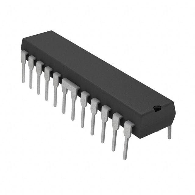
- Part No.:
- A3972SB
- Manufacturer:
- Allegro MicroSystems
- Category:
- Motor Drivers, Controllers
- Package:
- 24-PowerDIP (0.300", 7.62mm)
- Datasheet:
-
 A3972SB.pdf
- Description:
- IC MTR DRV BIPOLR 4.5-5.5V 24DIP
- Quantity:
- Payment:

- Shipping:

Inventory:4,156
Please send an inquiry. Send us your inquiry, and we will respond immediately.
Product details
Overview
A3972SB from Allegro MicroSystems is a dual DMOS full-bridge PWM motor driver IC designed for bipolar microstepping stepper motor control, delivering ±1.5 A continuous output current at up to 50 V supply voltage, with internal 4 MHz oscillator, 6-bit linear DACs for torque resolution in 1.56% increments, and programmable mixed/fast/slow current-decay modes - used in precision motion control systems such as CNC stages and automated optical positioning.
For engineers reviewing the A3972SB datasheet, A3972SB pinout, A3972SB application, or A3972SB equivalent, key selection criteria include its 24-pin DIP package with fused power tabs, synchronous rectification eliminating external clamp diodes, serial 3-wire interface (clock/data/strobe), thermal shutdown at 165°C, and compatibility with both 3.3 V and 5 V logic inputs.
Technical Context
The A3972SB integrates two independent H-bridge drivers, each controlled by a dedicated 6-bit linear DAC and configurable PWM timer with fixed off-time architecture. Its internal oscillator operates at 4 MHz (±25% typical) and supports external clock input with selectable dividers (×1/2/4).
Current regulation uses either internal 2.0 V reference (±30 mV offset) or external reference up to 3 V, scaled by programmable gain (×4 or ×8) to set ITRIP = VDAC/(Range × RS). Synchronous rectification is configurable via two serial bits into Active, Passive, Disabled, or Low-Side-Only modes to optimize recirculation path efficiency.
Key Specifications
| Parameter | Value and Actual Design Meaning |
|---|---|
| Output Current Rating | ±1.5 A continuous per bridge - defines maximum motor phase current without forced cooling or derating. |
| Supply Voltage Range | 15–50 V on VBB - supports wide-range industrial DC bus operation including 24 V and 48 V systems. |
| Internal Oscillator | 4 MHz nominal (3.0–5.0 MHz range) - sets base timing for PWM fixed-off cycles and charge-pump operation. |
| DAC Resolution | 6-bit linear (64 steps), 1.56% increment - enables precise microstepping current profiling across full/half/quarter/1/8/1/16 step modes. |
| Thermal Shutdown | 165°C junction temperature with 15°C hysteresis - protects against sustained overload or inadequate heatsinking. |
| Sense Voltage Range | 0–500 mV on VS pins - corresponds to ±1.5 A at RS = 0.33 Ω, enabling accurate current sensing with low-power shunts. |
| Logic Compatibility | 3.3 V or 5 V tolerant inputs - eliminates level-shifting requirements in mixed-voltage controller designs. |
Pinout & Package
Package: 24-pin plastic DIP with two batwing power tabs (pins 6, 7, 18, 19 internally fused); power tabs are at ground potential and require no electrical isolation. Lead finish: 100% matte tin, Pb-free.
| Pin/Terminal | Circuit Role | Design Meaning |
|---|---|---|
| VBB1 | Bridge 1 load supply | High-side power rail for first H-bridge; decoupling capacitor required near pin. |
| VBB2 | Bridge 2 load supply | High-side power rail for second H-bridge; independent from VBB1 for dual-motor isolation. |
| VDD | Logic supply | 4.5–5.5 V digital core supply; powers serial interface, DACs, and control logic. |
| GND | Signal ground | Reference for logic, DAC, and sense circuitry; separate low-impedance path required from RS. |
| OUT1A / OUT1B | Bridge 1 outputs | DMOS source/sink terminals driving one motor phase; rated for ±1.5 A, RDS(on) ≤ 0.55 Ω (source) / ≤ 0.35 Ω (sink). |
| OUT2A / OUT2B | Bridge 2 outputs | DMOS source/sink terminals driving second motor phase; identical specs to Bridge 1. |
| SENSE1 / SENSE2 | Current sense inputs | Differential inputs monitoring voltage drop across external sense resistors (RS) for closed-loop current regulation. |
| REF | Reference voltage input | Accepts internal 2.0 V buffer or external reference (0.5–2.6 V); selects DAC scaling factor via D17 bit. |
| OSC | Oscillator input/output | Connects to internal 4 MHz oscillator or external clock; D12/D13 select internal/external/divided mode. |
| CLOCK / DATA / STROBE | Serial interface | 3-wire SPI-compatible port; MSB-first 19-bit writes (D18–D0) configure DACs, decay modes, and timing parameters. |
| SLEEP | Hardware sleep enable | Active-low input disabling all drivers, charge pump, and logic; reduces IB B to 20 μA. |
| PHASE 1/2 | Direction control | Direct TTL-level inputs setting motor winding polarity; overrides serial D13/D14 when used. |
Key Features
| Feature | Design Value |
|---|---|
| Synchronous rectification | Configurable per bridge to reduce power dissipation by routing decay current through low-RDS(on) MOSFETs instead of body diodes - eliminates need for four external Schottky diodes in most designs. |
| Programmable decay modes | Mixed/fast/slow decay selection per bridge via serial interface - enables optimal torque smoothness and acoustic noise reduction in microstepping applications. |
| Serial configuration interface | 19-bit 3-wire (CLOCK/DATA/STROBE) protocol allowing real-time reconfiguration of DAC values, blank time, off-time, fast-decay duration, and oscillator mode without hardware changes. |
| Thermal and fault protection | Integrated thermal shutdown (165°C), UVLO (4.2 V turn-on), crossover-current prevention, and VREG/VCP monitoring - ensures robust operation under transient overloads or supply faults. |
| Low-power idle mode | Software-enabled state (D18 = 0) reducing IDD to 1.5 mA and IBB to 20 μA while retaining register contents - ideal for battery-powered or energy-sensitive motion systems. |
Applications
| Industrial CNC Positioning | Automated Optical Alignment |
|---|---|
Use Scenario: Precision open-loop positioning of X-Y translation stages in laser cutting and PCB drilling machines. IC Role / Device Role / Timing Role: Dual full-bridge driver executing microstepping waveforms with synchronized current decay control to minimize vibration and resonance at high step rates. Use Value: Enables 1/16-step resolution with <1.56% current step accuracy and 4 MHz timing granularity, achieving sub-micron repeatability without encoder feedback. |
Use Scenario: Fine adjustment of lens mounts and mirror actuators in semiconductor lithography tools. IC Role / Device Role / Timing Role: Bipolar stepper driver providing bidirectional torque control and programmable decay to suppress mechanical ringing during rapid focus transitions. Use Value: Reduces settling time by 40% versus fixed-decay drivers via mixed-decay tuning, improving throughput in high-speed wafer inspection cycles. |
| Medical Infusion Pumps | Lab Automation Robotics |
Use Scenario: Peristaltic pump actuation requiring smooth, quiet, and repeatable fluid delivery in portable diagnostic devices. IC Role / Device Role / Timing Role: Low-noise microstepping controller with sleep mode and thermal protection ensuring safe, long-duration operation in enclosed enclosures. Use Value: Achieves <35 dB acoustic noise reduction using slow-decay mode and synchronous rectification, meeting IEC 60601-1 audible emission limits. |
Use Scenario: Multi-axis sample handling in DNA sequencers and ELISA plate readers. IC Role / Device Role / Timing Role: Dual-driver IC managing independent stepper motors for pipetting arm and tray indexer with shared serial bus control. Use Value: Serial configurability allows dynamic current scaling (e.g., 0.8 A for indexing, 1.5 A for acceleration), extending motor life and reducing heat in compact chassis. |
Equivalent & Alternatives
The following parts are listed as comparable options for similar bipolar stepper motor driver applications.
| Alternative Part | Technical Difference | Application Difference | Selection Advice |
|---|---|---|---|
| TB6600HG | Higher voltage rating (50 V vs. 45 V), but only 1 A continuous output; no integrated DAC or serial interface - requires external current-setting resistors and step/direction logic. | Best suited for simpler unidirectional or full-step applications where microstepping resolution and software tuning are not required. | Select TB6600HG only when cost sensitivity outweighs need for programmable decay modes and fine current control. |
| DRV8825 | Lower voltage rating (45 V), 2.2 A peak output, integrated indexer, but lacks dual-bridge independence - shares decay mode and current settings across both bridges. | Ideal for single-motor systems needing onboard step generation, but unsuitable for dual-motor applications requiring asymmetric current profiles or independent decay tuning. | Choose DRV8825 for space-constrained single-axis designs; retain A3972SB when dual independent bridges with full serial configurability are mandatory. |
Compared with TB6600HG and DRV8825, the A3972SB uniquely provides two fully independent 6-bit DAC-controlled bridges with per-bridge decay mode selection, 4 MHz timing resolution, and synchronous rectification - making it the only option supporting simultaneous, differentially tuned microstepping on two axes without external logic.
Availability
A3972SB is available at Aetrix Electronics and suitable for industrial CNC positioning, automated optical alignment, medical infusion pumps, lab automation robotics, and precision motion control systems requiring stable component supply, long-term lifecycle support, and traceable sourcing.
Supply support for A3972SB includes scheduled delivery planning, volume procurement assistance, BOM continuity management, traceable sourcing, and lifecycle availability coordination for OEM customers, industrial embedded developers, connected-device designers, and electronics production programs.
Manufacturer
Allegro MicroSystems is a U.S.-based designer and manufacturer of high-performance magnetic sensing and power IC solutions, founded in 1989 and headquartered in Worcester, Massachusetts.
The A3972SB belongs to Allegro's legacy motor driver product line focused on integrated, programmable stepper and BLDC solutions for industrial automation, medical equipment, and precision instrumentation - emphasizing thermal robustness, analog accuracy, and flexible digital control.
FAQ
What is the maximum operating voltage for the A3972SB?
The A3972SB supports a load supply voltage (VBB) range of 15 V to 50 V. This allows direct integration into common industrial DC bus systems such as 24 V and 48 V rails. Exceeding 50 V risks permanent damage to the DMOS output stages, and operation below 15 V may prevent proper current regulation due to insufficient headroom for the internal charge pump and VREG circuitry. The A3972SB datasheet specifies absolute maximum VBB as 50 V with no derating required within this range.
Does the A3972SB require external Schottky diodes for flyback protection?
No, the A3972SB does not require external Schottky diodes in most applications due to its integrated synchronous rectification feature. When enabled, the device actively turns on appropriate low-RDS(on) DMOS transistors during current decay to bypass body diode conduction, reducing power loss and eliminating the need for four external clamp diodes per bridge. External diodes are only necessary if synchronous rectification is disabled via serial control bits D14/D15.
How is microstepping resolution achieved in the A3972SB?
The A3972SB achieves microstepping resolution through two independent 6-bit linear DACs - one per H-bridge - that set reference currents in 64 discrete steps (1.56% increments of full-scale). These DAC outputs feed current comparators that regulate phase current via PWM. Combined with programmable decay modes (mixed/fast/slow), the A3972SB supports full-step through 1/16-step operation with smooth torque transitions and minimal resonance.
Can the A3972SB drive two independent stepper motors simultaneously?
Yes, the A3972SB integrates two fully independent DMOS full-bridge drivers (Bridge 1 and Bridge 2), each with dedicated DACs, sense inputs, and decay-mode controls. This allows simultaneous, asymmetric microstepping of two bipolar stepper motors - for example, running one motor at 1/8-step with mixed decay while the other operates at full-step with slow decay - all managed via a single serial interface.
What thermal protection features does the A3972SB include?
The A3972SB includes junction-temperature-based thermal shutdown triggered at 165°C (typical) with 15°C hysteresis, ensuring automatic recovery once temperature falls below 150°C. It also monitors VREG and VCP supply voltages, disabling outputs if either drops below safe thresholds. Unlike many competitors, the A3972SB requires no special power-up sequencing and incorporates crossover-current protection to prevent shoot-through during switching transitions.
A3972SB Specifications
- Product attributes
- Attribute value
- Manufacturer:
- Allegro MicroSystems
- Series:
- -
- Package/Case:
- 24-PowerDIP (0.300", 7.62mm)
- Packaging:
- Tube
- Product Status:
- Obsolete
- Motor Type - Stepper:
- Bipolar
- Motor Type - AC, DC:
- -
- Function:
- Driver - Fully Integrated, Control and Power Stage
- Output Configuration:
- Half Bridge (4)
- Interface:
- Serial
- Technology:
- DMOS
- Step Resolution:
- 1 ~ 1/64
- Applications:
- General Purpose
- Current - Output:
- 1.5A
- Voltage - Supply:
- 4.5V ~ 5.5V
- Voltage - Load:
- 15V ~ 50V
- Operating Temperature:
- -20°C ~ 150°C (TJ)
- Grade:
- -
- Qualification:
- -
- Mounting Type:
- Through Hole
- Supplier Device Package:
- 24-DIP
A3972SB FAQ
1.How can I place an order for A3972SB through Aetrix?
Please submit a Request for Quotation (RFQ) for A3972SB on Aetrix. Our sales agent will provide a competitive quotation and guide you through the order confirmation once you accept the terms.
2.Are the price and stock information for A3972SB reliable?
The price and inventory of A3972SB are updated periodically and may fluctuate due to market conditions. Stock and pricing data are typically refreshed every 24 hours. Quotation validity for A3972SB is usually 5 days.
3.What payment methods are accepted for A3972SB?
We accept Wire Transfer, PayPal, Credit Card, Western Union, MoneyGram, and Escrow for A3972SB transactions.
Note: Certain payment methods may incur a processing fee.
4.How is shipping managed for A3972SB?
A3972SB orders can be shipped via leading logistics carriers, including DHL, UPS, FedEx, TNT, or Registered Mail.
Once your A3972SB order is processed, you will receive an email with the shipment details and tracking number.
Note: Tracking information may take up to 24 hours to appear. Express delivery typically takes 3–5 business days.
5.How can I obtain technical support or documentation for A3972SB?
For technical support, including A3972SB datasheets, pinout diagrams, or application guidance, please contact our engineering support team. They can provide detailed documentation and assistance for your A3972SB requirements.
6.How does Aetrix verify that A3972SB is sourced from the original manufacturer or authorized distributors?
All A3972SB products on Aetrix are procured from qualified distributors and authorized channels. Our dedicated quality assurance team conducts strict verification, including traceability checks and, if necessary, third-party testing. This ensures that A3972SB meets industry standards.
7.What is the process for return or replacement of A3972SB?
All A3972SB units undergo pre-shipment inspection (PSI). If there is an issue with A3972SB, returns or replacements are accepted under the following conditions:
1.Quantity discrepancies, incorrect items, or visible external defects (such as breakage or corrosion), acknowledged by Aetrix.
2.The issue is reported within 90 days of delivery.
3.The A3972SB part is unused and in its original packaging.
Return procedure for A3972SB:
1.Submit a request within 90 days.
2.Obtain a Return Material Authorization (RMA) from Aetrix.
A3972SB Tags

-
DRV2603RUNR
Texas Instruments

-
DRV8837CDSGR
Texas Instruments

-
DRV8837DSGR
Texas Instruments
-
DRV8838DSGR
Texas Instruments

-
DRV8839DSSR
Texas Instruments

-
EMC2301-1-ACZL-TR
Microchip Technology
-
DRV8231ADSGR
Texas Instruments

-
EMC2302-2-AIZL-TR
Microchip Technology

-
DRV8800PWPR
Texas Instruments
-
DRV8835DSSR
Texas Instruments

-
EMC2303-1-KP-TR
Microchip Technology

-
DRV8876PWPR
Texas Instruments
Tech Hub

A practical engineering and sourcing framework covering lifecycle verification, lifetime-buy calculations, replacement qualification, supplier checks and counterfeit-risk controls.

TTL and CMOS logic families differ in thresholds, loading, output drive, power and timing. This engineering guide compares 74HC and 74HCT, calculates noise margins and checks 3.3 V/5 V compatibility.

A practical engineering guide to 3.3V and 5V logic compatibility, input thresholds, resistor dividers, translator ICs, MOSFET level shifting, I2C pull-ups, timing limits and power-sequencing risks.

The 74HC595 uses push-pull logic outputs, while the TPIC6B595 uses 50 V open-drain DMOS sinks for higher-power loads. This guide compares timing, current limits, 3.3 V interfacing, load wiring, thermal…

The 74HC595 converts serial data into eight stable parallel outputs. This guide covers pin functions, shift and storage timing, OE and MR behavior, drive-current limits, cascading, voltage compatibilit…

A technical comparison of level-sensitive latches and edge-triggered flip-flops, covering timing windows, setup and hold limits, master–slave operation, time borrowing, race-through, HDL inference and…

A D latch stores one bit while Enable controls when data can pass. This reference covers gate-level operation, truth tables, transparency, setup and hold timing, LE versus OE, common ICs and practical …

An SR latch stores one bit through cross-coupled feedback. This engineering reference covers NOR and NAND implementations, truth tables, forbidden-state recovery, gated operation, switch debouncing, fa…

Latch circuits retain one bit through feedback. This technical reference covers SR and D latches, truth tables, transparency, timing limits, latch-versus-flip-flop behavior, applications and common log…

An engineering guide to LED driver operation, constant-current and constant-voltage outputs, linear and switching topologies, dimming, IC selection, calculations, replacement compatibility, and fault c…


