
 My Inquiry
 My Account


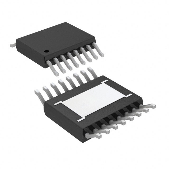
Allegro MicroSystems A4406KLPTR-T
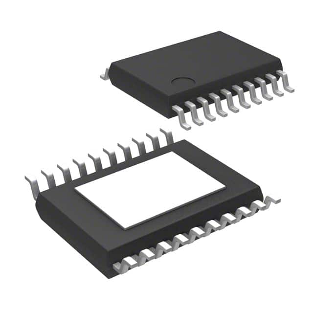
- Part No.:
- A4406KLPTR-T
- Manufacturer:
- Allegro MicroSystems
- Category:
- Voltage Regulators - Linear + Switching
- Package:
- 20-TSSOP (0.173", 4.40mm Width) Exposed Pad
- Datasheet:
-
 A4406KLPTR-T.pdf
- Description:
- IC REG TRIPLE BUCK/LNR 20TSSOP
- Quantity:
- Payment:

- Shipping:

Inventory:2,002
Please send an inquiry. Send us your inquiry, and we will respond immediately.
Product details
Overview
A4406KLPTR-T from Allegro MicroSystems is an AEC-Q100 Grade 0 automotive power management IC integrating a 2.2 MHz constant on-time buck pre-regulator (5.45 V output), internal 5 V LDO (V5P, 400 mA, short-to-battery protected), and external 3.3 V DMOS linear regulator driver (V33/G33, programmable up to 500 mA). It operates from 5.5–36 V input, supports cold-crank and load-dump conditions, and delivers stable dual-rail power for CAN and microprocessor subsystems in under-hood applications.
For engineers reviewing the A4406KLPTR-T datasheet, A4406KLPTR-T pinout, A4406KLPTR-T application, or A4406KLPTR-T equivalent, key selection considerations include its VIN range (5.5–36 V), junction temperature rating (−40°C to +150°C), integrated valley-current-sensing buck control, dual enable inputs (ENB/ENBAT), and NPOR with adjustable delay - all critical for automotive control module design and qualification.
Technical Context
The A4406KLPTR-T implements a valley-current-mode constant on-time (COT) buck architecture with dynamically adjusted switching period: nominal 450 ns at 13.5 V input, extending to 1.6 µs at low/high VIN extremes to maintain regulation across 5.5–46 V functional range. Its buck stage feeds both an internal 5 V tracking LDO (V5P) and a VREG output that powers an external N-channel FET driver for 3.3 V regulation.
Protection logic includes pulse-by-pulse valley current limiting (220 mV threshold), latched LX short-circuit detection (5 A peak), missing diode protection (−1.2 V @ 157 ns), thermal shutdown (170°C trip, 20°C hysteresis), and independent UVLO monitoring for VREG and V33 to assert NPOR. Power-on reset timing is set via CPOR capacitor (20 ms typical with 0.22 µF).
Key Specifications
| Parameter | Value and Actual Design Meaning |
|---|---|
| VIN Operating Range | 5.5 V to 36 V - supports automotive start-stop, cold crank (down to 5.5 V), and load dump (up to 50 V absolute max) |
| Buck Switching Frequency | 2.2 MHz nominal - enables use of small ceramic capacitors and avoids AM band EMI |
| V5P Output | 5.0 V ±1%, 400 mA - internally regulated, short-to-battery protected, tracks V33 with 1.515 ratio |
| V33 Driver Capability | Programmable 3.3 V output up to 500 mA - uses external MOSFET with G33 gate driver and CLV33 current sense |
| Junction Temperature Range | −40°C to +150°C - qualified per AEC-Q100 Grade 0 for under-hood deployment |
| Enable Inputs | ENB (logic-level, 2.0 V high threshold) and ENBAT (ignition-level, 4.0 V high threshold) - ORed internally for flexible system control |
| NPOR Delay | Adjustable via CPOR capacitor - 20 ms typical with 0.22 µF, ensures reliable microcontroller reset sequencing |
Pinout & Package
Package: 20-pin TSSOP with exposed thermal pad (suffix LP), 1.2 mm max height, lead-free with matte-tin plating.
| Pin/Terminal | Circuit Role | Design Meaning |
|---|---|---|
| VIN (Pin 1) | Main input supply | Accepts 5.5–36 V automotive battery rail; 50 V absolute max withstand |
| GND (Pin 2) | Power ground reference | Common return for buck, LDOs, and drivers; connects to exposed thermal pad |
| TON (Pin 3) | Buck on-time programming | Resistor to VIN sets tON (e.g., 412 kΩ → 200 ns typ at 13.5 V) |
| ENBAT (Pin 4) | High-voltage ignition enable | 1 kΩ series resistor required; 4.0 V threshold enables operation during key-on |
| ENB (Pin 5) | Logic-level enable | Microcontroller-driven; 2.0 V threshold; ORed with ENBAT for redundant control |
| ENBATS (Pin 6) | Ignition status indicator | Open-drain output pulled low when ENBAT active; 11 ms turn-on delay |
| NPOR (Pin 7) | Power-on reset signal | Active-low open drain; asserts when VREG or V33 drops below UVLO thresholds |
| CPOR (Pin 8) | NPOR delay capacitor | 0.22 µF sets ~20 ms delay; charges at −13 µA for precise reset timing |
| V5P (Pins 9,10) | 5 V protected LDO output | Dual-pin layout for high-current delivery; short-to-battery protected; 400 mA rated |
| VCP (Pin 20) | Charge pump reservoir | Generates ~6.6 V above VIN to drive external 3.3 V FET gate (G33) |
| LX (Pin 17) | Buck switching node | Connects to external inductor and freewheeling diode; monitored for short-circuit and missing-diode faults |
| ISEN+ / ISEN− (Pins 16,15) | Valley current sense inputs | 220 mV threshold triggers pulse-by-pulse current limiting; enables accurate valley-mode control |
| VREG (Pin 14) | Buck DC output | 5.45 V pre-regulated supply for V5P LDO and V33 driver; 733 mA valley current limit |
| CLV33 (Pin 13) | V33 current limit sense | 200 mV threshold sets V33 overcurrent trip; used with external RCL (e.g., 390 mΩ → 323 mA) |
| G33 (Pin 12) | External 3.3 V FET gate driver | Drives N-channel MOSFET gate; supports up to 15 V gate swing for low RDS(on) FETs |
| V33 (Pin 11) | 3.3 V linear regulator output | Externally generated via G33-driven FET and RDROP; accuracy ±2.1% (3.23–3.37 V) |
Key Features
| Feature | Design Value |
|---|---|
| AEC-Q100 Grade 0 qualification | Validated for −40°C to +150°C junction operation - meets stringent automotive under-hood reliability requirements |
| Valley-current sensing buck control | Enables shortest possible on-times (80 ns min) and stable operation across wide VIN range without slope compensation |
| Dual enable architecture (ENB + ENBAT) | Supports both microcontroller logic control and vehicle ignition-switch control - eliminates need for external level-shifting circuitry |
| V5P short-to-battery protection | Prevents damage when V5P output is shorted to battery voltage - critical for wiring harness fault tolerance |
| Adjustable NPOR with capacitor programming | CPOR pin allows precise reset delay tuning (e.g., 0.22 µF = 20 ms) to match microcontroller startup timing requirements |
| Missing asynchronous diode protection | Latches off if LX falls below −1.2 V for >157 ns - prevents destructive negative voltage transients due to diode failure or omission |
Applications
| Electronic Power Steering (EPS) | Transmission Control Unit (TCU) |
|---|---|
|
Use Scenario: High-temperature EPS motor control module requiring dual-rail power under hood with vibration, thermal cycling, and battery transients. IC Role / Device Role / Timing Role: Primary power manager supplying isolated 5 V (for MCU/CAN) and 3.3 V (for sensors/ASICs) from 12 V battery with cold-crank support. Use Value: A4406KLPTR-T's 150°C junction rating, 2.2 MHz switching, and short-to-battery protection ensure uninterrupted operation during steering assist events and load dumps. |
Use Scenario: TCU operating near engine block with ambient temperatures up to 135°C and exposure to 50 V load-dump surges. IC Role / Device Role / Timing Role: Central regulator delivering tightly tracked 5 V and 3.3 V rails to transmission solenoid drivers, position sensors, and communication interfaces. Use Value: A4406KLPTR-T's V5P/V33 tracking ratio (1.515) and independent UVLO monitoring guarantee synchronized power-up and fault-safe shutdown during gear shifts. |
| Antilock Braking System (ABS) | Emissions Control Module |
|
Use Scenario: ABS controller needing fast, deterministic reset signaling and robust power under aggressive braking-induced voltage sags. IC Role / Device Role / Timing Role: Provides NPOR with adjustable delay to coordinate MCU reset with hydraulic valve actuation timing after ignition-on. Use Value: A4406KLPTR-T's CPOR-programmable NPOR (20 ms typical) and ENBATS ignition status output enable precise brake system boot sequencing. |
Use Scenario: Emissions module (e.g., SCR dosing controller) deployed in exhaust proximity with extreme thermal gradients and EMI sensitivity. IC Role / Device Role / Timing Role: Supplies clean, low-noise 3.3 V for NOx sensor interface and 5 V for CAN FD communication, rejecting AM-band noise. Use Value: A4406KLPTR-T's 2.2 MHz constant-frequency operation avoids AM radio interference while maintaining efficiency at light loads via pulse-skipping mode. |
Equivalent & Alternatives
The following parts are listed as comparable options for similar automotive dual-output power management applications.
| Alternative Part | Technical Difference | Application Difference | Selection Advice |
|---|---|---|---|
| A4409KLPTR-T | Successor device with improved thermal performance (RθJA = 28°C/W vs. 32°C/W), extended VIN range (4.5–46 V), and enhanced V5P current capability (500 mA vs. 400 mA) | Designed for new designs requiring higher efficiency and longer lifetime in high-ambient environments; not pin-compatible with A4406KLPTR-T | Select A4409KLPTR-T for new automotive designs where higher output current, lower thermal resistance, and wider input range are required. |
| MPQ4333-AEC1 | Monolithic 3.3 V/5 V dual-output buck converter (no external LDO driver); 2.2 MHz fixed frequency; AEC-Q100 Grade 1 (−40°C to +125°C) | Lacks external 3.3 V FET driver and V5P short-to-battery protection; suitable for less demanding under-hood locations | Choose MPQ4333-AEC1 only when board space is constrained and full AEC-Q100 Grade 0 operation is not required. |
Compared with A4406KLPTR-T, the A4409KLPTR-T offers higher V5P current and better thermal metrics for next-gen modules, while the MPQ4333-AEC1 provides compact integration at the cost of reduced ruggedness and missing key protections like short-to-battery and missing-diode latch-off.
Availability
A4406KLPTR-T is available at Aetrix Electronics and suitable for automotive control modules, electronic power steering systems, and transmission control units requiring stable component supply despite discontinuation status for new designs.
Supply support for A4406KLPTR-T includes scheduled delivery planning, volume procurement assistance, BOM continuity management, traceable sourcing, and lifecycle availability coordination for OEM customers, industrial embedded developers, connected-device designers, and electronics production programs.
Manufacturer
Allegro MicroSystems is a global leader in magnetic sensing and power ICs, specializing in high-reliability semiconductor solutions for automotive, industrial, and consumer markets.
The A4406 product line was designed specifically for automotive under-hood power management, delivering integrated buck + dual-LDO architectures with AEC-Q100 Grade 0 qualification and comprehensive fault protection.
FAQ
Is the A4406KLPTR-T still recommended for new designs?
No. The A4406KLPTR-T is a discontinued product and should not be purchased for new design applications. Allegro explicitly recommends the A4409KLPTR-T as the designated replacement for both existing customer transitions and new designs. While Aetrix Electronics maintains limited legacy supply for continuity support, engineering teams are advised to migrate to A4409KLPTR-T to ensure long-term availability and access to updated specifications and technical support for the A4406KLPTR-T.
What is the function of the ENBAT and ENB pins on the A4406KLPTR-T?
The A4406KLPTR-T features two independent enable inputs: ENBAT accepts high-voltage ignition signals (4.0 V threshold) via a 1 kΩ series resistor, while ENB accepts standard logic-level signals (2.0 V threshold) from a microcontroller. These inputs are ORed internally - asserting either one enables the device. This dual-enable architecture allows seamless integration into vehicle architectures where power must be controlled by both the ignition switch and the MCU, eliminating the need for external level shifters or discrete logic in the A4406KLPTR-T system design.
How does the A4406KLPTR-T protect against short-to-battery faults on the V5P output?
The A4406KLPTR-T integrates dedicated short-to-battery protection on the V5P output. When a short occurs between V5P and the battery rail, internal circuitry limits current and clamps the output voltage to prevent damage to the regulator or downstream circuitry. This protection is distinct from general overcurrent foldback and is specifically designed to survive sustained battery shorts - a critical requirement for automotive wiring harness applications where V5P may drive long traces exposed to mechanical damage. The A4406KLPTR-T datasheet confirms this feature is implemented and tested per AEC-Q100 stress conditions.
Can the A4406KLPTR-T operate with input voltages below 5.5 V?
No. The A4406KLPTR-T has a minimum functional input voltage of 5.5 V, as specified in its Absolute Maximum Ratings and Electrical Characteristics tables. Below this threshold, the device enters undervoltage lockout (UVLO) and ceases regulation. Although the buck stage can enter 100% duty-cycle dropout mode at low VIN, this behavior is only guaranteed above 5.5 V. Operation below 5.5 V is outside specification and may result in unpredictable output behavior, loss of NPOR assertion, or failure to meet AEC-Q100 Grade 0 performance requirements for the A4406KLPTR-T.
What is the purpose of the CLV33 pin on the A4406KLPTR-T?
The CLV33 pin on the A4406KLPTR-T serves as the current limit sense input for the external 3.3 V linear regulator. It monitors the voltage drop across an external sense resistor (RCL) placed between the V33 output and the source of the external N-channel FET. When the voltage at CLV33 exceeds 200 mV (typical), the A4406KLPTR-T initiates overcurrent foldback on the V33 rail. This allows designers to precisely set the V33 current limit - for example, using a 390 mΩ resistor yields a 323 mA trip point - enabling robust protection tailored to the specific external FET and load requirements of the A4406KLPTR-T application.
A4406KLPTR-T Specifications
- Product attributes
- Attribute value
- Manufacturer:
- Allegro MicroSystems
- Series:
- -
- Package/Case:
- 20-TSSOP (0.173", 4.40mm Width) Exposed Pad
- Packaging:
- Tape & Reel (TR)
- Product Status:
- Obsolete
- Topology:
- Step-Down (Buck) (1), Linear (LDO) (2)
- Number of Outputs:
- 3
- Frequency - Switching:
- 2.2MHz
- Voltage/Current - Output 1:
- 5.45V, 2.5A
- Voltage/Current - Output 2:
- 5V
- Voltage/Current - Output 3:
- 3.3V, 500mA
- w/LED Driver:
- No
- w/Supervisor:
- No
- w/Sequencer:
- No
- Voltage - Supply:
- 5.5V ~ 36V
- Operating Temperature:
- -40°C ~ 150°C (TJ)
- Grade:
- Automotive
- Qualification:
- AEC-Q100
- Mounting Type:
- Surface Mount
- Supplier Device Package:
- 20-TSSOP-EP
A4406KLPTR-T FAQ
1.How can I place an order for A4406KLPTR-T through Aetrix?
Please submit a Request for Quotation (RFQ) for A4406KLPTR-T on Aetrix. Our sales agent will provide a competitive quotation and guide you through the order confirmation once you accept the terms.
2.Are the price and stock information for A4406KLPTR-T reliable?
The price and inventory of A4406KLPTR-T are updated periodically and may fluctuate due to market conditions. Stock and pricing data are typically refreshed every 24 hours. Quotation validity for A4406KLPTR-T is usually 5 days.
3.What payment methods are accepted for A4406KLPTR-T?
We accept Wire Transfer, PayPal, Credit Card, Western Union, MoneyGram, and Escrow for A4406KLPTR-T transactions.
Note: Certain payment methods may incur a processing fee.
4.How is shipping managed for A4406KLPTR-T?
A4406KLPTR-T orders can be shipped via leading logistics carriers, including DHL, UPS, FedEx, TNT, or Registered Mail.
Once your A4406KLPTR-T order is processed, you will receive an email with the shipment details and tracking number.
Note: Tracking information may take up to 24 hours to appear. Express delivery typically takes 3–5 business days.
5.How can I obtain technical support or documentation for A4406KLPTR-T?
For technical support, including A4406KLPTR-T datasheets, pinout diagrams, or application guidance, please contact our engineering support team. They can provide detailed documentation and assistance for your A4406KLPTR-T requirements.
6.How does Aetrix verify that A4406KLPTR-T is sourced from the original manufacturer or authorized distributors?
All A4406KLPTR-T products on Aetrix are procured from qualified distributors and authorized channels. Our dedicated quality assurance team conducts strict verification, including traceability checks and, if necessary, third-party testing. This ensures that A4406KLPTR-T meets industry standards.
7.What is the process for return or replacement of A4406KLPTR-T?
All A4406KLPTR-T units undergo pre-shipment inspection (PSI). If there is an issue with A4406KLPTR-T, returns or replacements are accepted under the following conditions:
1.Quantity discrepancies, incorrect items, or visible external defects (such as breakage or corrosion), acknowledged by Aetrix.
2.The issue is reported within 90 days of delivery.
3.The A4406KLPTR-T part is unused and in its original packaging.
Return procedure for A4406KLPTR-T:
1.Submit a request within 90 days.
2.Obtain a Return Material Authorization (RMA) from Aetrix.
A4406KLPTR-T Tags

-
TPS6521905RHBR
Texas Instruments
-
MIC3385YHL-TR
Microchip Technology
-
A4402ELPTR-T
Allegro MicroSystems

-
LM26480SQ-AA/NOPB
Texas Instruments
-
A4402KLPTR-T
Allegro MicroSystems
-
BD71847AMWV-E2
ROHM Semiconductor
-
ADP5040ACPZ-1-R7
Analog Devices Inc.
-
LT3048IDC#TRPBF
Analog Devices Inc.
-
ADP5037ACPZ-R7
Analog Devices Inc.

-
XRP7714ILB-F
MaxLinear, Inc.
-
LTC3260EDE#TRPBF
Analog Devices Inc.
-
LTC3260EMSE#PBF
Analog Devices Inc.
Tech Hub

A practical engineering and sourcing framework covering lifecycle verification, lifetime-buy calculations, replacement qualification, supplier checks and counterfeit-risk controls.

TTL and CMOS logic families differ in thresholds, loading, output drive, power and timing. This engineering guide compares 74HC and 74HCT, calculates noise margins and checks 3.3 V/5 V compatibility.

A practical engineering guide to 3.3V and 5V logic compatibility, input thresholds, resistor dividers, translator ICs, MOSFET level shifting, I2C pull-ups, timing limits and power-sequencing risks.

The 74HC595 uses push-pull logic outputs, while the TPIC6B595 uses 50 V open-drain DMOS sinks for higher-power loads. This guide compares timing, current limits, 3.3 V interfacing, load wiring, thermal…

The 74HC595 converts serial data into eight stable parallel outputs. This guide covers pin functions, shift and storage timing, OE and MR behavior, drive-current limits, cascading, voltage compatibilit…

A technical comparison of level-sensitive latches and edge-triggered flip-flops, covering timing windows, setup and hold limits, master–slave operation, time borrowing, race-through, HDL inference and…

A D latch stores one bit while Enable controls when data can pass. This reference covers gate-level operation, truth tables, transparency, setup and hold timing, LE versus OE, common ICs and practical …

An SR latch stores one bit through cross-coupled feedback. This engineering reference covers NOR and NAND implementations, truth tables, forbidden-state recovery, gated operation, switch debouncing, fa…

Latch circuits retain one bit through feedback. This technical reference covers SR and D latches, truth tables, transparency, timing limits, latch-versus-flip-flop behavior, applications and common log…

An engineering guide to LED driver operation, constant-current and constant-voltage outputs, linear and switching topologies, dimming, IC selection, calculations, replacement compatibility, and fault c…


