
 My Inquiry
 My Account


Allegro MicroSystems A4964KJPTR-T
- Part No.:
- A4964KJPTR-T
- Manufacturer:
- Allegro MicroSystems
- Category:
- Motor Drivers, Controllers
- Package:
- 32-LQFP Exposed Pad
- Datasheet:
-
 A4964KJPTR-T.pdf
- Description:
- IC MOTOR DRIVER 5.5V-50V 32QFP
- Quantity:
- Payment:

- Shipping:

Inventory:6,832
Please send an inquiry. Send us your inquiry, and we will respond immediately.
Product details
Overview
A4964KJPTR-T from Allegro MicroSystems is a three-phase, sensorless brushless DC (BLDC) motor controller IC designed for automotive fuel, oil, and urea pumps. It drives external N-channel MOSFETs using sinusoidal commutation, supports 5.5–50 V supply, integrates LIN/PWM physical interface with wake capability, and provides MCU watchdog/reset and diagnostics including undervoltage, overtemperature, and bridge fault detection.
For engineers reviewing the A4964KJPTR-T datasheet, A4964KJPTR-T pinout, A4964KJPTR-T application, or A4964KJPTR-T equivalent, this device is selected for high-reliability automotive BLDC motor control where sensorless startup, closed-loop speed/torque regulation, and integrated safety diagnostics are required - especially in constrained-space, thermally demanding pump modules.
Technical Context
The A4964KJPTR-T implements rotor position estimation via back-EMF zero-crossing detection without Hall sensors, enabling windmill detection, pre-rotation synchronization, and soft-start sinusoidal drive. Its gate drive architecture includes programmable slew-rate-controlled high-side (bootstrap) and low-side outputs with dead-time control (0.1–3.15 µs), supporting 3-phase PWM modulation with overmodulation handling.
Control is executed via SPI-compatible serial interface or LIN/PWM physical layer, allowing configuration of operating mode (stand-alone or MCU-coordinated), current limit (25–200 mV sense threshold), speed resolution (0.095–3.2 Hz), and diagnostic masks. Integrated regulators supply VLR (3.3/5.0 V logic), VREG (7.5–11.7 V gate drive), and bootstrap charge management.
Key Specifications
| Parameter | Value and Actual Design Meaning |
|---|---|
| Supply Voltage Range | 5.5 V to 50 V - supports full automotive battery range including cold-crank (5.5 V) and load-dump (50 V) conditions. |
| Motor Drive Type | Sensorless 3-phase sinusoidal commutation - eliminates need for Hall/encoder sensors while enabling smooth torque and low acoustic noise. |
| Control Interface | SPI-compatible serial + LIN/PWM physical layer - enables dual-mode communication: high-speed configuration (SPI) and robust low-pin-count bus control (LIN). |
| Diagnostic Coverage | Integrated VBB/VREG/VLR undervoltage, overtemperature (175 °C trip), VDS fault monitoring, and bootstrap UV detection - reduces external protection circuitry. |
| Thermal Performance | RθJA = 23 °C/W (JP package, 4-layer PCB) - enables operation up to 150 °C ambient with appropriate heatsinking for under-hood applications. |
| Gate Drive Capability | Programmable high-side (GHx) and low-side (GLx) currents (±5–75 mA) with 190 ns turn-on / 120 ns turn-off - ensures fast, controlled switching of external N-MOSFETs. |
| Startup Support | Windmill detection and synchronization - allows reliable restart of rotating motors (e.g., fuel pumps during engine cranking) without mechanical position feedback. |
Pinout & Package
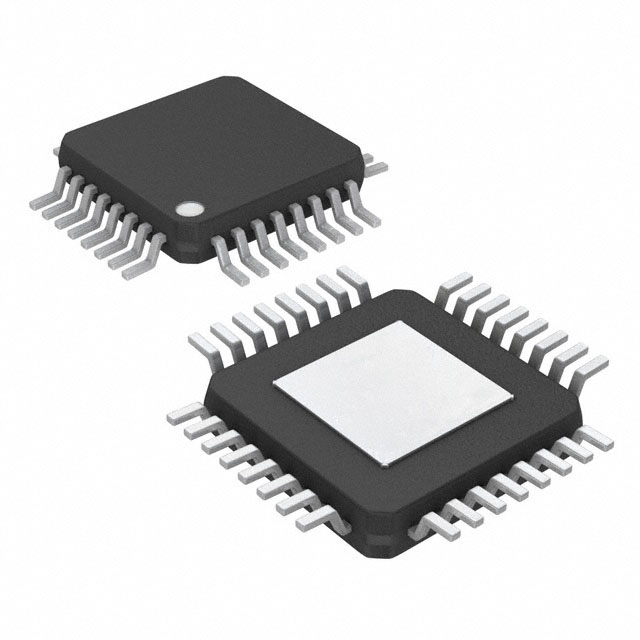
The A4964KJPTR-T is supplied in a 32-lead eQFP package with exposed thermal pad (suffix JP), measuring 7 mm × 7 mm × 1.6 mm max height. Thermal pad must be connected to GND for optimal power dissipation and EMI performance.
| Pin/Terminal | Circuit Role | Design Meaning |
|---|---|---|
| SA, SB, SC | Motor phase terminals | Connect directly to motor windings; support high-current 3-phase output with VBRG drain voltage sensing for fault detection. |
| GHA, GHB, GHC | High-side gate drive outputs | Drive external N-MOSFET gates via bootstrap capacitors (CA/CB/CC); regulated by internal charge pump and VREG. |
| GLA, GLB, GLC | Low-side gate drive outputs | Directly drive low-side N-MOSFET gates from VREG-regulated supply; enable synchronous rectification and braking. |
| CSP, CSM | Current sense amplifier inputs | Measure motor phase current via shunt resistor; provide peak limiting (25–200 mV threshold) and average current readback via SPI. |
| STRn, SCK, SDI, SDO | SPI interface signals | Enable full register access for configuration, status readback, and real-time control; support daisy-chaining in multi-controller systems. |
| LIN, LTX, LRX | LIN bus physical interface | Provide ISO 17987-compliant wake-up, diagnostics, and command transmission over single-wire bus; tolerate ±40 V transients. |
| IG, WDOG, MRSTn | Ignition interface & MCU supervision | IG monitors ignition switch state; WDOG resets device if MCU fails to refresh; MRSTn asserts reset to MCU on fault or POR. |
| DIAG, VBRG, VLR, VREG | Diagnostics & supply outputs | DIAG provides programmable open-drain fault signaling; VBRG monitors high-side drain voltage; VLR/VREG supply regulated logic/gate drive rails. |
Key Features
| Feature | Design Value |
|---|---|
| Sensorless sinusoidal commutation | Enables smooth, low-noise motor operation without position sensors - critical for automotive cabin comfort and pump longevity. |
| Windmill detection & synchronization | Allows safe restart of spinning loads (e.g., fuel flow inertia) without forced alignment - prevents torque shock and MOSFET stress. |
| Integrated LIN physical layer | Eliminates need for external LIN transceiver; supports wake-on-bus and single-wire diagnostic feedback (e.g., speed, current, faults). |
| Programmable gate drive slew rate | Reduces EMI and dv/dt-induced shoot-through risk by tuning GHx/GLx current limits - essential for high-voltage automotive systems. |
| VDS fault qualification with blanking | Detects short-circuit and overcurrent events at MOSFET drains with configurable blank time (1–6.6 µs) to ignore switching transients. |
| Multi-rail regulation (VLR/VREG) | Provides independent 3.3/5.0 V logic supply and 7.5–11.7 V gate drive supply - simplifies system BOM and improves noise isolation. |
Applications
| Automotive Fuel Pumps | Automotive Urea (AdBlue®) Pumps |
|---|---|
Use Scenario: High-pressure diesel fuel delivery in modern common-rail engines requiring precise flow control and fail-safe shutdown. IC Role / Device Role / Timing Role: Primary motor controller managing sinusoidal drive, closed-loop speed regulation, and real-time diagnostics including VDS fault detection on each phase. Use Value: Enables compliance with ISO 26262 ASIL-B requirements through integrated watchdog, reset, and fault reporting via DIAG/LIN - reducing system-level safety hardware. | Use Scenario: Metered injection of aqueous urea solution into diesel exhaust for SCR NOx reduction, operating in harsh under-hood environments. IC Role / Device Role / Timing Role: Stand-alone BLDC controller with windmill restart, temperature monitoring (–40 to 150 °C), and LIN-based diagnostics for OEM telematics integration. Use Value: Eliminates external position sensors and transceivers - shrinking PCB area by >30% while maintaining ASIL-A functional safety integrity. |
| Engine Cooling Fans | Oil Circulation Pumps |
Use Scenario: Variable-speed radiator fan control responding to coolant temperature and vehicle speed, subject to wide input voltage swings and EMI. IC Role / Device Role / Timing Role: Sensorless motor controller with 5.5–50 V operation, bootstrap gate drive, and LIN wake-up - enabling ultra-low sleep current (10 µA). Use Value: Reduces system power consumption during idle/stop-start cycles while maintaining rapid response to thermal events via programmable speed ramp rates. | Use Scenario: Lubrication system pump in electric powertrain gearboxes, requiring continuous operation at elevated temperatures and vibration resistance. IC Role / Device Role / Timing Role: Robust motor driver with overtemperature lockout (175 °C), VBRG drain monitoring, and thermal pad-connected QFP package for enhanced reliability. Use Value: Extends service life beyond 15,000 hours MTBF by eliminating thermal runaway risks through integrated junction temperature measurement (±5 °C accuracy). |
Equivalent & Alternatives
The following parts are listed as comparable options for similar three-phase sensorless BLDC motor controller applications.
| Alternative Part | Technical Difference | Application Difference | Selection Advice |
|---|---|---|---|
| MP6532GQ-Z | Integrated MOSFETs (40 V, 3 A), no external FET support; lacks LIN interface and ignition switch input. | Targeted at low-power fans/blowers (<100 W); unsuitable for high-voltage automotive pumps requiring external 100 V+ FETs. | Select only for space-constrained, low-power applications where integrated drivers suffice and LIN is not required. |
| DRV3212AQPWPRQ1 | Higher voltage rating (65 V), supports both sensored and sensorless modes, but requires external current sense amplifier and separate LIN transceiver. | Better suited for hybrid/electric vehicle traction auxiliary systems needing higher voltage margin and flexible position sensing. | Choose when design requires >50 V operation or dual-mode (Hall + BEMF) flexibility - adds BOM cost but increases functional safety coverage. |
Compared with MP6532GQ-Z and DRV3212AQPWPRQ1, the A4964KJPTR-T uniquely combines external N-FET support, integrated LIN PHY, ignition interface, and automotive-grade diagnostics in a single 32-pin QFP - making it optimal for cost-sensitive, high-reliability 12/24 V pump modules where board space and component count are critical.
Availability
A4964KJPTR-T is available at Aetrix Electronics and suitable for automotive fuel pumps, urea dosing systems, and engine cooling fans requiring stable component supply across extended temperature ranges and long production lifecycles.
Supply support for A4964KJPTR-T includes scheduled delivery planning, volume procurement assistance, BOM continuity management, traceable sourcing, and lifecycle availability coordination for OEM customers, industrial embedded developers, connected-device designers, and electronics production programs.
Manufacturer
Allegro MicroSystems is a global leader in precision sensing and power ICs, headquartered in Manchester, NH, with deep expertise in magnetic sensing, motor control, and automotive-grade mixed-signal solutions.
The A4964 product line was engineered specifically for automotive BLDC motor control in fluid-handling applications - emphasizing sensorless reliability, integrated safety, and seamless integration with vehicle communication buses like LIN.
FAQ
What is the primary function of the A4964KJPTR-T in an automotive system?
The A4964KJPTR-T serves as a dedicated three-phase sensorless BLDC motor controller for automotive fluid pumps and fans. It manages sinusoidal commutation using back-EMF sensing, regulates motor speed/torque via SPI or LIN, and delivers integrated diagnostics including VDS fault detection, overtemperature shutdown, and undervoltage protection - all within the A4964KJPTR-T's 32-lead eQFP package.
Does the A4964KJPTR-T require external position sensors for motor commutation?
No, the A4964KJPTR-T performs sensorless commutation by continuously monitoring motor back-EMF zero-crossings on phases SA, SB, and SC. It includes dedicated circuitry for windmill detection and synchronization, enabling reliable startup and operation of rotating loads without Hall effect sensors or encoders - a core feature of the A4964KJPTR-T design.
What communication interfaces does the A4964KJPTR-T support?
The A4964KJPTR-T supports two independent interfaces: a 4-wire SPI-compatible serial interface (STRn, SCK, SDI, SDO) for full register configuration and diagnostics readback, and a LIN 2.2-compliant physical layer (LIN, LTX, LRX) for wake-up, command transmission, and single-wire diagnostic feedback - both fully implemented within the A4964KJPTR-T silicon.
How does the A4964KJPTR-T handle fault conditions such as overtemperature or MOSFET short circuits?
The A4964KJPTR-T integrates chip-level and motor-level fault detection: overtemperature triggers at 175 °C with 15 °C hysteresis; VDS faults are qualified using programmable blank time (1–6.6 µs) on VBRG inputs; undervoltage lockouts act on VBB, VREG, and VLR rails. All faults assert the DIAG pin and can force MRSTn reset - behavior defined in the A4964KJPTR-T's diagnostic register map.
What is the thermal pad connection requirement for the A4964KJPTR-T's 32-lead eQFP package?
The thermal pad on the A4964KJPTR-T's 32-lead eQFP package must be soldered to a solid GND plane on the PCB to ensure effective heat dissipation and electromagnetic compatibility. This connection is mandatory for achieving the specified RθJA of 23 °C/W (4-layer board) and maintaining junction temperature below 165 °C under continuous 150 °C ambient operation - a key requirement validated for the A4964KJPTR-T.
A4964KJPTR-T Specifications
- Product attributes
- Attribute value
- Manufacturer:
- Allegro MicroSystems
- Series:
- -
- Package/Case:
- 32-LQFP Exposed Pad
- Packaging:
- Tape & Reel (TR)
- Product Status:
- Active
- Motor Type - Stepper:
- -
- Motor Type - AC, DC:
- Brushless DC (BLDC)
- Function:
- Controller - Commutation, Direction Management
- Output Configuration:
- -
- Interface:
- SPI
- Technology:
- -
- Step Resolution:
- -
- Applications:
- -
- Current - Output:
- -
- Voltage - Supply:
- 5.5V ~ 50V
- Voltage - Load:
- -
- Operating Temperature:
- -40°C ~ 150°C (TA)
- Grade:
- Automotive
- Qualification:
- -
- Mounting Type:
- Surface Mount
- Supplier Device Package:
- 32-QFP (7x7)
A4964KJPTR-T FAQ
1.How can I place an order for A4964KJPTR-T through Aetrix?
Please submit a Request for Quotation (RFQ) for A4964KJPTR-T on Aetrix. Our sales agent will provide a competitive quotation and guide you through the order confirmation once you accept the terms.
2.Are the price and stock information for A4964KJPTR-T reliable?
The price and inventory of A4964KJPTR-T are updated periodically and may fluctuate due to market conditions. Stock and pricing data are typically refreshed every 24 hours. Quotation validity for A4964KJPTR-T is usually 5 days.
3.What payment methods are accepted for A4964KJPTR-T?
We accept Wire Transfer, PayPal, Credit Card, Western Union, MoneyGram, and Escrow for A4964KJPTR-T transactions.
Note: Certain payment methods may incur a processing fee.
4.How is shipping managed for A4964KJPTR-T?
A4964KJPTR-T orders can be shipped via leading logistics carriers, including DHL, UPS, FedEx, TNT, or Registered Mail.
Once your A4964KJPTR-T order is processed, you will receive an email with the shipment details and tracking number.
Note: Tracking information may take up to 24 hours to appear. Express delivery typically takes 3–5 business days.
5.How can I obtain technical support or documentation for A4964KJPTR-T?
For technical support, including A4964KJPTR-T datasheets, pinout diagrams, or application guidance, please contact our engineering support team. They can provide detailed documentation and assistance for your A4964KJPTR-T requirements.
6.How does Aetrix verify that A4964KJPTR-T is sourced from the original manufacturer or authorized distributors?
All A4964KJPTR-T products on Aetrix are procured from qualified distributors and authorized channels. Our dedicated quality assurance team conducts strict verification, including traceability checks and, if necessary, third-party testing. This ensures that A4964KJPTR-T meets industry standards.
7.What is the process for return or replacement of A4964KJPTR-T?
All A4964KJPTR-T units undergo pre-shipment inspection (PSI). If there is an issue with A4964KJPTR-T, returns or replacements are accepted under the following conditions:
1.Quantity discrepancies, incorrect items, or visible external defects (such as breakage or corrosion), acknowledged by Aetrix.
2.The issue is reported within 90 days of delivery.
3.The A4964KJPTR-T part is unused and in its original packaging.
Return procedure for A4964KJPTR-T:
1.Submit a request within 90 days.
2.Obtain a Return Material Authorization (RMA) from Aetrix.
A4964KJPTR-T Tags

-
DRV2603RUNR
Texas Instruments

-
DRV8837CDSGR
Texas Instruments

-
DRV8837DSGR
Texas Instruments
-
DRV8838DSGR
Texas Instruments

-
DRV8839DSSR
Texas Instruments

-
EMC2301-1-ACZL-TR
Microchip Technology
-
DRV8231ADSGR
Texas Instruments

-
EMC2302-2-AIZL-TR
Microchip Technology

-
DRV8800PWPR
Texas Instruments
-
DRV8835DSSR
Texas Instruments

-
EMC2303-1-KP-TR
Microchip Technology

-
DRV8876PWPR
Texas Instruments
Tech Hub

A practical engineering and sourcing framework covering lifecycle verification, lifetime-buy calculations, replacement qualification, supplier checks and counterfeit-risk controls.

TTL and CMOS logic families differ in thresholds, loading, output drive, power and timing. This engineering guide compares 74HC and 74HCT, calculates noise margins and checks 3.3 V/5 V compatibility.

A practical engineering guide to 3.3V and 5V logic compatibility, input thresholds, resistor dividers, translator ICs, MOSFET level shifting, I2C pull-ups, timing limits and power-sequencing risks.

The 74HC595 uses push-pull logic outputs, while the TPIC6B595 uses 50 V open-drain DMOS sinks for higher-power loads. This guide compares timing, current limits, 3.3 V interfacing, load wiring, thermal…

The 74HC595 converts serial data into eight stable parallel outputs. This guide covers pin functions, shift and storage timing, OE and MR behavior, drive-current limits, cascading, voltage compatibilit…

A technical comparison of level-sensitive latches and edge-triggered flip-flops, covering timing windows, setup and hold limits, master–slave operation, time borrowing, race-through, HDL inference and…

A D latch stores one bit while Enable controls when data can pass. This reference covers gate-level operation, truth tables, transparency, setup and hold timing, LE versus OE, common ICs and practical …

An SR latch stores one bit through cross-coupled feedback. This engineering reference covers NOR and NAND implementations, truth tables, forbidden-state recovery, gated operation, switch debouncing, fa…

Latch circuits retain one bit through feedback. This technical reference covers SR and D latches, truth tables, transparency, timing limits, latch-versus-flip-flop behavior, applications and common log…

An engineering guide to LED driver operation, constant-current and constant-voltage outputs, linear and switching topologies, dimming, IC selection, calculations, replacement compatibility, and fault c…


