
 My Inquiry
 My Account


Allegro MicroSystems A5364CA-T
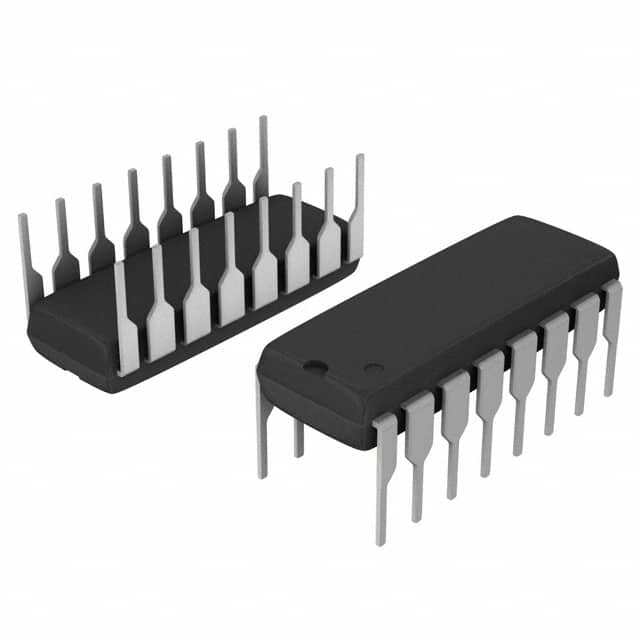
- Part No.:
- A5364CA-T
- Manufacturer:
- Allegro MicroSystems
- Category:
- Sensor and Detector Interfaces
- Package:
- 16-DIP (0.300", 7.62mm)
- Datasheet:
-
 A5364CA-T.pdf
- Description:
- IC SMOKE DETECTOR ION 16DIP
- Quantity:
- Payment:

- Shipping:

Inventory:1,873
Please send an inquiry. Send us your inquiry, and we will respond immediately.
Product details
Overview
A5364CA-T from Allegro MicroSystems is a low-current CMOS ionization smoke detector ASIC with interconnect capability, 16-pin DIP package, UL217 recognition (File #S2113), temporal horn pattern compliance (UL217/NFPA72/ISO8201), and integrated active guard amplifiers for chamber leakage suppression. It enables battery-operated residential smoke alarms with up to 125-unit networking.
For engineers reviewing the A5364CA-T datasheet, A5364CA-T pinout, A5364CA-T application, or A5364CA-T equivalent, key selection criteria include standby current (5.0 μA typ. at 9 V), sensitivity/low-battery threshold adjustability via external resistors, piezoelectric horn drive capability (±16 mA), and UL-recognized functional safety architecture for ionization chamber interfaces.
Technical Context
The A5364CA-T integrates a 1.67 s strobed oscillator that powers circuitry for only 10 ms per cycle to minimize average current draw, with built-in power-on reset and reverse battery protection. Its dual active guard outputs (GUARD1/GUARD2) maintain voltage within ±100 mV of DETECT IN to suppress surface leakage in ionization chambers.
Smoke detection uses comparator-based threshold comparison (VDETECTIN < VSENSITIVITYSET) with 130 mV typical hysteresis, while low-battery sensing occurs every 24 cycles (~40 s) using an internal reference and adjustable LOW-V SET pin. Horn outputs (HORN1/HORN2) deliver temporal patterns compliant with UL217: 500 ms on / 500 ms off ×3, then 1500 ms off.
Key Specifications
| Parameter | Value and Actual Design Meaning |
|---|---|
| Supply Voltage | 6.0–12.0 V - supports standard 9 V alkaline battery operation with margin for aging and temperature drift |
| Standby Current | 5.0 μA typ. at 9 V - enables >5 years battery life in residential smoke alarms without frequent replacement |
| Oscillator Period (no smoke) | 1.67 s - defines ultra-low-power sampling interval for ionization chamber monitoring |
| Horn Output Drive | ±16 mA - directly drives common piezoelectric horns without external amplification |
| Hysteresis | 130 mV typ. - reduces false alarms by preventing oscillation near trip threshold during marginal smoke conditions |
| UL Recognition | UL217 File #S2113 - certifies suitability for use in UL-listed residential smoke alarm products |
| Operating Temp | 0°C to 50°C - matches indoor residential ambient requirements without derating |
| Package | 16-pin DIP (0.300" wide) - compatible with through-hole assembly and legacy smoke alarm PCB layouts |
Pinout & Package
Package: 16-pin plastic dual in-line package (DIP), 0.300" body width, Pb-free matte tin leadframe plating (suffix –T).
| Pin/Terminal | Circuit Role | Design Meaning |
|---|---|---|
| 1, 4 | No Connection | Unused pins; must remain unconnected to avoid parasitic coupling or latch-up risk |
| 2 | I/O Interconnect | Open-drain output with internal pulldown; enables daisy-chained alarm propagation across ≤125 units |
| 3 | LOW-V SET | Adjusts low-battery threshold (7.2–7.8 V) via resistor to VDD/VSS; enables field calibration for battery chemistry |
| 5 | LED Driver | Sinks up to 10 mA; pulses per UL217 timing (10 ms on / 40 s off) for status indication |
| 6 | VDD | Main supply input; includes internal reverse-battery protection diode |
| 7 | TIMING RES | Sets internal bias current; 8.2 MΩ resistor establishes 1.67 s oscillator period |
| 8 | FEEDBACK | Horn feedback input; monitors piezo impedance to stabilize drive waveform |
| 9 | VSS | Ground reference; return path for all analog/digital blocks and horn outputs |
| 10, 11 | HORN1 / HORN2 | Complementary push-pull outputs; generate differential voltage across piezo element for efficient acoustic output |
| 12 | OSC CAP | Connects to 0.1 μF low-leakage capacitor (PTFE/polystyrene); defines oscillator timing accuracy and stability |
| 13 | SENSITIVITY SET | Adjusts smoke trip point via resistor to VDD/VSS; compensates for chamber geometry and alpha source decay |
| 14, 16 | GUARD1 / GUARD2 | Active guard buffers; track DETECT IN within ±100 mV to eliminate PCB surface leakage errors |
| 15 | DETECT IN | High-impedance (±1.0 pA) input from ionization chamber; requires guarded routing per UL217 |
Key Features
| Feature | Design Value |
|---|---|
| UL217 Temporal Horn Pattern | Hardware-enforced 0.5 s on / 0.5 s off ×3, then 1.5 s off - eliminates need for external timing logic in certified designs |
| Dual Active Guard Amplifiers | GUARD1/GUARD2 maintain ±100 mV tracking of DETECT IN - prevents false alarms from humidity-induced PCB leakage |
| Strobed Power Architecture | 10 ms active window every 1.67 s - achieves 5 μA typical standby current without sacrificing detection reliability |
| Interconnect I/O with 3 s Delay | Drives high after 3 s local alarm confirmation - prevents nuisance triggering from EMI or transient noise on shared bus |
| Low-Battery Pulse Test | Integrated check every ~40 s during LED pulse - avoids dedicated test circuitry and preserves BOM simplicity |
| Pb-Free Matte Tin Leadframe | RoHS-compliant 100% matte tin plating - ensures solderability and long-term corrosion resistance in humid environments |
Applications
| Residential Ionization Smoke Alarm | Multi-Unit Interconnected System |
|---|---|
Use Scenario: Standalone ceiling-mounted smoke detector powered by 9 V alkaline battery in single-family dwelling. IC Role / Device Role / Timing Role: Primary smoke sensing ASIC performing chamber voltage sampling, temporal horn pattern generation, and LED status signaling. Use Value: 5 μA standby current extends battery life beyond 5 years; UL217 recognition enables direct listing without additional system-level certification effort. | Use Scenario: 12-unit apartment building with hardwired interconnect wiring between detectors. IC Role / Device Role / Timing Role: Network node using I/O pin to propagate alarm signals across shared bus; suppresses local LED during remote alarms. Use Value: Eliminates need for external microcontroller or communication IC; 3 s delay prevents false network-wide alarms from EMI spikes. |
| Smoke Detector with Adjustable Sensitivity | Low-Power Safety Sensor Platform |
Use Scenario: Detector deployed in high-humidity coastal environment requiring reduced false-alarm rate. IC Role / Device Role / Timing Role: Sensitivity calibrated via SENSITIVITY SET resistor to compensate for chamber contamination and alpha source decay. Use Value: Field-adjustable trip point maintains consistent response over 10-year product lifetime without hardware revision. | Use Scenario: Battery-powered carbon monoxide detector reusing A5364CA-T's low-power architecture with modified sensor interface. IC Role / Device Role / Timing Role: General-purpose ultra-low-power analog front-end with guarded inputs, strobed sampling, and programmable thresholds. Use Value: Reduces development time by reusing proven UL-certified timing, power management, and horn drive subsystems. |
Equivalent & Alternatives
The following parts are listed as comparable options for similar ionization smoke detector ASIC applications.
| Alternative Part | Technical Difference | Application Difference | Selection Advice |
|---|---|---|---|
| ISL28134CAZ-T7A | Higher standby current (12 μA), no UL217 recognition, no interconnect I/O, 8-pin SOIC package | Requires external timing logic and microcontroller for horn pattern; not suitable for UL-listed standalone alarms | Select only for non-certified prototypes or CO detector variants where UL compliance is deferred to system level |
| SM550A-16 | Same 16-pin DIP footprint, but lacks active guard outputs and UL217 temporal pattern hardware; 8 μA standby | Needs external op-amps for guarded inputs and discrete timer IC for horn pattern - increases BOM cost and board area | Consider only when redesigning legacy systems with existing SM550A-16 footprints and no UL217 requirement |
Compared with ISL28134CAZ-T7A and SM550A-16, the A5364CA-T delivers certified temporal horn timing, dual active guards, and 5 μA standby in a drop-in UL-recognized package-reducing design validation effort and enabling faster time-to-certification for residential smoke alarms.
Availability
A5364CA-T is available at Aetrix Electronics and suitable for residential smoke alarms, interconnected safety systems, and low-power battery-operated safety sensors requiring stable component supply and UL217 compliance.
Supply support for A5364CA-T includes scheduled delivery planning, volume procurement assistance, BOM continuity management, traceable sourcing, and lifecycle availability coordination for OEM customers, industrial embedded developers, connected-device designers, and electronics production programs.
Manufacturer
Allegro MicroSystems is a U.S.-based semiconductor company specializing in magnetic sensing, power ICs, and safety-critical analog devices for automotive and industrial markets.
The A5364CA-T belongs to Allegro's smoke detector ASIC product line, designed specifically to integrate UL217-compliant timing, interconnect logic, and ultra-low-power analog front-ends into single-chip solutions for residential fire safety equipment.
FAQ
What is the minimum supply voltage required for reliable operation of the A5364CA-T?
The A5364CA-T operates reliably from 6.0 V to 12.0 V. At 6.0 V, all specifications-including 5.0 μA standby current, 130 mV hysteresis, and temporal horn pattern timing-remain valid per the datasheet. Operation below 6.0 V risks failure of the internal power-on reset and may cause erratic behavior during low-battery transitions. The A5364CA-T is engineered for 9 V alkaline batteries, which typically deliver 6.0–9.5 V over their service life.
How does the A5364CA-T implement active guarding on the DETECT IN pin?
The A5364CA-T implements active guarding using two dedicated amplifier outputs: GUARD1 (Pin 14) and GUARD2 (Pin 16). These outputs track the voltage at DETECT IN (Pin 15) within ±100 mV across the full operating temperature range. This eliminates surface leakage currents on PCB traces adjacent to the high-impedance ionization chamber input, a critical requirement for UL217 compliance. Unlike passive guarding, the A5364CA-T's active guards remain powered continuously-not strobed-ensuring constant protection during both standby and alarm states.
Can the A5364CA-T drive piezoelectric horns directly without external components?
Yes, the A5364CA-T drives piezoelectric horns directly via complementary HORN1 (Pin 10) and HORN2 (Pin 11) outputs, each capable of sourcing/sinking ±16 mA at 9.0 V. The device includes internal feedback (FEEDBACK, Pin 8) to stabilize drive waveforms across varying horn impedances. External components are only needed for tuning: a 0.1 μF low-leakage capacitor on OSC CAP (Pin 12) sets timing, and optional resistors on SENSITIVITY SET (Pin 13) and LOW-V SET (Pin 3) calibrate thresholds. No external transistors, drivers, or timing ICs are required for basic UL217-compliant operation.
What is the purpose of the 3-second delay on the I/O pin during alarm propagation?
The 3-second delay on the I/O pin (Pin 2) of the A5364CA-T prevents false interconnect alarms caused by electrical transients, EMI, or momentary chamber disturbances. After local smoke detection is confirmed across multiple sampling cycles, the I/O pin transitions high only after this fixed delay. This ensures that only sustained, validated alarm conditions trigger network-wide horn activation-meeting UL217's reliability requirements for interconnected systems. During the delay, local horn and LED remain fully active, providing immediate occupant warning while preventing spurious propagation.
Is the A5364CA-T RoHS-compliant and suitable for modern manufacturing processes?
Yes, the A5364CA-T is RoHS-compliant with 100% matte tin leadframe plating (Pb-free), as indicated by the "–T" suffix. It meets JEDEC MS-001 BB mechanical standards for 16-pin DIP packages and is qualified for reflow and wave soldering per IPC-J-STD-020. The matte tin finish ensures robust solderability, resistance to whisker growth, and long-term reliability in humid residential environments-critical for safety-critical smoke alarm applications where field failures are unacceptable. Aetrix Electronics guarantees full traceability and lifecycle support for the A5364CA-T in production programs.
A5364CA-T Specifications
- Product attributes
- Attribute value
- Manufacturer:
- Allegro MicroSystems
- Package/Case:
- 16-DIP (0.300", 7.62mm)
- Series:
- -
- Packaging:
- Tube
- Product Status:
- Obsolete
- Programmable:
- Not Verified
- Type:
- Smoke Detector
- Input Type:
- Ionization
- Output Type:
- Voltage
- Current - Supply:
- 12 µA
- Operating Temperature:
- -25°C ~ 75°C
- Grade:
- -
- Qualification:
- -
- Mounting Type:
- Through Hole
- Supplier Device Package:
- 16-DIP
A5364CA-T FAQ
1.How can I place an order for A5364CA-T through Aetrix?
Please submit a Request for Quotation (RFQ) for A5364CA-T on Aetrix. Our sales agent will provide a competitive quotation and guide you through the order confirmation once you accept the terms.
2.Are the price and stock information for A5364CA-T reliable?
The price and inventory of A5364CA-T are updated periodically and may fluctuate due to market conditions. Stock and pricing data are typically refreshed every 24 hours. Quotation validity for A5364CA-T is usually 5 days.
3.What payment methods are accepted for A5364CA-T?
We accept Wire Transfer, PayPal, Credit Card, Western Union, MoneyGram, and Escrow for A5364CA-T transactions.
Note: Certain payment methods may incur a processing fee.
4.How is shipping managed for A5364CA-T?
A5364CA-T orders can be shipped via leading logistics carriers, including DHL, UPS, FedEx, TNT, or Registered Mail.
Once your A5364CA-T order is processed, you will receive an email with the shipment details and tracking number.
Note: Tracking information may take up to 24 hours to appear. Express delivery typically takes 3–5 business days.
5.How can I obtain technical support or documentation for A5364CA-T?
For technical support, including A5364CA-T datasheets, pinout diagrams, or application guidance, please contact our engineering support team. They can provide detailed documentation and assistance for your A5364CA-T requirements.
6.How does Aetrix verify that A5364CA-T is sourced from the original manufacturer or authorized distributors?
All A5364CA-T products on Aetrix are procured from qualified distributors and authorized channels. Our dedicated quality assurance team conducts strict verification, including traceability checks and, if necessary, third-party testing. This ensures that A5364CA-T meets industry standards.
7.What is the process for return or replacement of A5364CA-T?
All A5364CA-T units undergo pre-shipment inspection (PSI). If there is an issue with A5364CA-T, returns or replacements are accepted under the following conditions:
1.Quantity discrepancies, incorrect items, or visible external defects (such as breakage or corrosion), acknowledged by Aetrix.
2.The issue is reported within 90 days of delivery.
3.The A5364CA-T part is unused and in its original packaging.
Return procedure for A5364CA-T:
1.Submit a request within 90 days.
2.Obtain a Return Material Authorization (RMA) from Aetrix.
A5364CA-T Tags

-
RE46C100S8TF
Microchip Technology

-
XTR111AIDRCR
Texas Instruments

-
XTR111AIDGQR
Texas Instruments

-
XTR117AIDGKR
Texas Instruments
-
XTR111AIDGQT
Texas Instruments

-
XTR115UA/2K5
Texas Instruments

-
MAX14626ETT+T
Analog Devices Inc./Maxim Integrated
-
XTR116UA/2K5
Texas Instruments
-
XTR115U/2K5
Texas Instruments
-
XTR116U/2K5
Texas Instruments

-
PGA308AIDGSR
Texas Instruments

-
XTR300AIRGWR
Texas Instruments
Tech Hub

A practical engineering and sourcing framework covering lifecycle verification, lifetime-buy calculations, replacement qualification, supplier checks and counterfeit-risk controls.

TTL and CMOS logic families differ in thresholds, loading, output drive, power and timing. This engineering guide compares 74HC and 74HCT, calculates noise margins and checks 3.3 V/5 V compatibility.

A practical engineering guide to 3.3V and 5V logic compatibility, input thresholds, resistor dividers, translator ICs, MOSFET level shifting, I2C pull-ups, timing limits and power-sequencing risks.

The 74HC595 uses push-pull logic outputs, while the TPIC6B595 uses 50 V open-drain DMOS sinks for higher-power loads. This guide compares timing, current limits, 3.3 V interfacing, load wiring, thermal…

The 74HC595 converts serial data into eight stable parallel outputs. This guide covers pin functions, shift and storage timing, OE and MR behavior, drive-current limits, cascading, voltage compatibilit…

A technical comparison of level-sensitive latches and edge-triggered flip-flops, covering timing windows, setup and hold limits, master–slave operation, time borrowing, race-through, HDL inference and…

A D latch stores one bit while Enable controls when data can pass. This reference covers gate-level operation, truth tables, transparency, setup and hold timing, LE versus OE, common ICs and practical …

An SR latch stores one bit through cross-coupled feedback. This engineering reference covers NOR and NAND implementations, truth tables, forbidden-state recovery, gated operation, switch debouncing, fa…

Latch circuits retain one bit through feedback. This technical reference covers SR and D latches, truth tables, transparency, timing limits, latch-versus-flip-flop behavior, applications and common log…

An engineering guide to LED driver operation, constant-current and constant-voltage outputs, linear and switching topologies, dimming, IC selection, calculations, replacement compatibility, and fault c…


