
 My Inquiry
 My Account


Allegro MicroSystems A5366CA
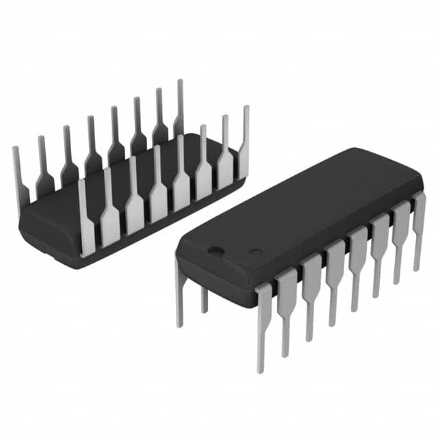
- Part No.:
- A5366CA
- Manufacturer:
- Allegro MicroSystems
- Category:
- Sensor and Detector Interfaces
- Package:
- 16-DIP (0.300", 7.62mm)
- Datasheet:
-
 A5366CA.pdf
- Description:
- IC SMOKE DETECTOR PHOTO 16DIP
- Quantity:
- Payment:

- Shipping:

Inventory:1,893
Please send an inquiry. Send us your inquiry, and we will respond immediately.
Product details
Overview
A5366CA from Allegro MicroSystems is a BiCMOS photoelectric smoke detector IC with integrated photoamplifier, strobe driver, IRED control, piezoelectric horn interface, interconnect logic, and UL217/UL268-compliant temporal alarm pattern generation. It operates from 6–12 V, draws only 12 μA average standby current, supports up to 50-unit networking, and delivers calibrated smoke detection in residential and commercial fire-safety systems.
For engineers reviewing the A5366CA datasheet, A5366CA pinout, A5366CA application, or A5366CA equivalent, this page provides verified technical context, UL-recognized functional specifications, validated 16-pin DIP package mapping, real-world timing behavior (e.g., 100 μs smoke sampling every 10 s), and confirmed alternatives for smoke detector design and replacement.
Technical Context
The A5366CA implements a three-stage speedup sensing scheme that requires two consecutive degraded sensitivity cycles before issuing a chirp warning and mandates three valid smoke samples before triggering full alarm - reducing false alarms while maintaining rapid response. Its variable-gain photoamplifier uses external C1 (0.047 μF) and C2 (4700 pF) capacitors to switch between supervisory (high-gain) and standby (low-gain +10% post-alarm) modes under precise internal timing control.
Internal oscillator sets core timing: nominal 10.4 ms period (tosc), 105 μs IRED pulse width (thigh), and synchronized 9.5–11.5 ms STROBE/LED pulse widths. The I/O pin supports noise-immune interconnect via 42 ms sampling intervals and 95–137 ms high-level persistence requirement to prevent spurious remote alarms.
Key Specifications
| Parameter | Value and Actual Design Meaning |
|---|---|
| Supply Voltage Range | 6–12 V - Enables direct use with standard 9 V alkaline batteries without regulation |
| Standby Current | 12 μA typical - Extends battery life to >10 years in typical smoke detector deployments |
| Operating Temperature | –25°C to +75°C - Validated for indoor residential and commercial ceiling-mount environments |
| UL Recognition | UL217 & UL268 per file #S2113 - Certified for use in listed smoke alarms without additional system-level requalification |
| Interconnect Capacity | Up to 50 units - Supports large-scale residential complexes or multi-unit buildings via wired daisy-chain |
| Smoke Sampling Interval | 100 μs every 10 s - Minimizes power consumption while maintaining reliable particle detection duty cycle |
| Temporal Horn Pattern | 0.5 s on / 0.5 s off / 0.5 s on / 0.5 s off / 0.5 s on / 1.5 s off - Complies with NFPA72 and ISO8201 audible alarm requirements |
Pinout & Package
Package: 16-pin plastic dual in-line package (DIP), through-hole mount, Pb-free option available (suffix –T). Thermal resistance RθJA = 38°C/W on 4-layer JEDEC PCB.
| Pin/Terminal | Circuit Role | Design Meaning |
|---|---|---|
| 1 C1 | Photoamplifier gain capacitor input (supervisory mode) | Sets high gain (Ae = 1 + C1/10 pF) during push-to-test and chamber monitoring; max 0.1 μF |
| 2 C2 | Photoamplifier gain capacitor input (standby mode) | Sets low gain with series resistor; gain increases ~10% after local alarm detection |
| 3 DETECT | Photodiode cathode input | Zero-bias input for low-dark-current photodiode; requires parallel shunt resistor |
| 4 STROBE | Strobed reference voltage output | Provides regulated VDD – 5 V reference for photoamplifier circuitry during sampling |
| 5 VDD | Positive supply input | Accepts 6–12 V DC; powers all internal blocks including horn drivers and IRED control |
| 6 IRED | Infrared LED driver output | Pulsed NPN base drive (2.85–3.35 V @ –6 mA); inactive during horn/LED activation to reduce noise |
| 7 I/O | Interconnect input/output | Drives high during local alarm to trigger networked units; samples every 42 ms with noise filtering |
| 8 HORN1 | Piezo transducer electrode output | Drives metal support electrode of self-resonating piezoelectric horn |
| 9 HORN2 | Piezo transducer complementary output | Drives ceramic electrode; works with HORN1 and FEEDBACK for resonant oscillation |
| 10 FEEDBACK | Piezo feedback electrode input | Enables self-oscillation; must be tied to VSS if unused |
| 11 LED | Visible LED driver (open-drain) | Indicates status: standby (43 s), local smoke (0.5 s), timer mode (10 s); also loads battery during low-VDD test |
| 12 OSC CAP | Oscillator capacitor connection | With TIMING RES, sets internal clock low time (Tlow = 0.693 × R × C) |
| 13 TIMING RES | Oscillator timing resistor connection | With OSC CAP, sets internal clock high time/IRED pulse width (Thigh = 0.693 × R × C) |
| 14 VSS | Negative supply (ground) | Reference for all analog and digital circuitry; connects to battery negative terminal |
| 15 HUSH | Timer mode enable/reference | Enables 10-minute "hush" mode when >1.5 V; sets reduced-sensitivity comparator reference during timer |
| 16 TEST | Push-to-test and diagnostic entry | Triggers calibration mode (400 μA sink) or push-to-test (VDD pull-up); resets hush timer on falling edge |
Key Features
| Feature | Design Value |
|---|---|
| Low-power smoke sampling | 100 μs active window every 10 s reduces average current to 12 μA - enables decade-long battery life |
| Three-stage speedup sensing | Requires 3 valid smoke samples before alarm, but reduces time-to-audible-alert by optimizing strobe/IRED timing sequence |
| Integrated UL-compliant horn driver | Generates exact temporal pattern (0.5/0.5/0.5/0.5/0.5/1.5 s) without external microcontroller or timing components |
| Self-calibrating chamber monitoring | Automatically tests sensitivity every 43 s using C1 gain; triggers chirp after 2 consecutive failures - detects dirty/obstructed chambers |
| Networked interconnect logic | I/O pin handles up to 50-unit daisy-chain with built-in 95–137 ms noise immunity window - eliminates need for external bus arbitration |
| Single-pin push-to-test & diagnostics | TEST pin supports both user-activated smoke simulation and factory calibration mode via current-sink entry - no extra test pads required |
Applications
| Residential Smoke Alarms | Commercial Ceiling-Mount Detectors |
|---|---|
Use Scenario: Battery-powered ceiling-mounted unit in single-family home bedrooms and hallways. IC Role / Device Role / Timing Role: Primary smoke detection engine performing periodic chamber sampling, low-battery monitoring, and UL217-compliant audible alarm generation. Use Value: 12 μA standby current extends 9 V battery life beyond 10 years; integrated hush mode suppresses nuisance alarms from cooking steam without disabling detection. |
Use Scenario: Interconnected detectors across office floors with centralized alarm notification. IC Role / Device Role / Timing Role: Network node in daisy-chained topology; receives remote I/O signals and triggers local horn/LED per UL268 requirements. Use Value: Supports up to 50-unit interconnect with hardware-level noise filtering - eliminates false alarms from EMI or line transients in shared wiring. |
| Multi-Unit Apartment Systems | Serviceable Detector Modules |
Use Scenario: Retrofit installation in aging apartment buildings requiring minimal rewiring. IC Role / Device Role / Timing Role: Standalone detector with wired I/O interconnect enabling retrofit without new control panel infrastructure. Use Value: Uses existing 2-wire interconnect cabling; internal charge-dump circuit on I/O pin handles distributed capacitance from long cable runs. |
Use Scenario: Field-replaceable detector module with factory-calibrated sensitivity and self-test capability. IC Role / Device Role / Timing Role: Embedded calibration engine using C1/C2 gain switching and TEST-pin diagnostic mode for end-of-line verification. Use Value: Diagnostic Test/Calibration Mode allows production-line validation of chamber response without external test equipment or firmware. |
Equivalent & Alternatives
The following parts are listed as comparable options for similar photoelectric smoke detector IC applications.
| Alternative Part | Technical Difference | Application Difference | Selection Advice |
|---|---|---|---|
| A5366CLWTR-T | Identical functionality and pinout; SOICW surface-mount package (16-pin), tape-and-reel packaging (1000/reel), Pb-free matte-tin plating | Designed for automated SMT assembly; requires PCB redesign from through-hole to SOICW footprint | Select for high-volume manufacturing where automated placement and smaller board area are priorities |
| SL1301 | Lower integration: lacks built-in temporal horn pattern generator, requires external microcontroller for alarm timing; no integrated hush mode or chamber test logic | Needs external MCU and timing components to meet UL217; not drop-in compatible for A5366CA-based designs | Choose only when cost-sensitive designs can accommodate added BOM complexity and firmware development |
Compared with A5366CLWTR-T, the A5366CA offers identical electrical and functional behavior but in a through-hole DIP package optimized for prototyping and low-volume assembly; compared with SL1301, the A5366CA eliminates external timing and control circuitry, reduces qualification effort via UL file #S2113, and enables faster time-to-market for certified smoke alarms.
Availability
A5366CA is available at Aetrix Electronics and suitable for residential fire-safety systems, commercial building alarm networks, multi-unit housing interconnects, and serviceable detector modules requiring stable component supply and long-lifecycle support.
Supply support for A5366CA includes scheduled delivery planning, volume procurement assistance, BOM continuity management, traceable sourcing, and lifecycle availability coordination for OEM customers, industrial embedded developers, connected-device designers, and electronics production programs.
Manufacturer
Allegro MicroSystems is a U.S.-based semiconductor company specializing in magnetic sensing, motor driver, and safety-critical analog ICs, headquartered in Worcester, Massachusetts.
The A5366CA belongs to Allegro's photoelectric smoke detector IC product line, engineered specifically to integrate UL217/UL268-compliant signal conditioning, interconnect logic, and temporal alarm generation into a single BiCMOS device for battery-operated life-safety applications.
FAQ
What is the operating voltage range for the A5366CA?
The A5366CA operates from 6 V to 12 V DC referenced to VSS. This range accommodates standard 9 V alkaline batteries across their full discharge curve - including down to the 6.9–7.5 V low-battery threshold where the device initiates chirp warnings. Operation outside this range may damage the IC or invalidate UL recognition.
How does the A5366CA achieve UL217 and UL268 compliance?
The A5366CA is UL Recognized under file #S2113 for use in smoke alarms complying with UL217 (residential) and UL268 (commercial) standards. Compliance is achieved through on-die temporal horn pattern generation, three-stage smoke confirmation logic, built-in low-battery and chamber degradation detection, and validated 100 μs/10 s sampling architecture - all verified by Underwriters Laboratories.
Can the A5366CA drive a piezoelectric horn directly?
Yes, the A5366CA drives self-resonating piezoelectric horns directly via HORN1, HORN2, and FEEDBACK pins. It generates the full UL217 temporal pattern (0.5/0.5/0.5/0.5/0.5/1.5 s) without external components. External passive components (e.g., 8.2 kΩ resistor, 22 Ω series resistor) are required per the typical application diagram to match horn impedance and ensure reliable startup.
What is the purpose of the C1 and C2 pins on the A5366CA?
C1 and C2 set photoamplifier gain for different operational modes: C1 (0.047 μF typical) configures high gain during push-to-test and chamber monitoring; C2 (4700 pF typical) sets low gain during standby. Gain is calculated as Ae = 1 + C/10 pF. The A5366CA internally switches between them and boosts C2 gain by ~10% after local alarm detection to reduce false triggers.
Does the A5366CA support interconnection with other smoke detectors?
Yes, the A5366CA supports wired interconnection of up to 50 units via its I/O pin. When any unit detects smoke, it drives I/O high, triggering alarms in all connected devices. The I/O interface includes hardware noise filtering requiring 95–137 ms of sustained high level to register - preventing false alarms from EMI or contact bounce in shared wiring.
A5366CA Specifications
- Product attributes
- Attribute value
- Manufacturer:
- Allegro MicroSystems
- Package/Case:
- 16-DIP (0.300", 7.62mm)
- Series:
- -
- Packaging:
- Tube
- Product Status:
- Obsolete
- Programmable:
- Not Verified
- Type:
- Smoke Detector
- Input Type:
- Photoelectric
- Output Type:
- Voltage
- Current - Supply:
- 12 mA
- Operating Temperature:
- -25°C ~ 75°C
- Grade:
- -
- Qualification:
- -
- Mounting Type:
- Through Hole
- Supplier Device Package:
- 16-DIP
A5366CA FAQ
1.How can I place an order for A5366CA through Aetrix?
Please submit a Request for Quotation (RFQ) for A5366CA on Aetrix. Our sales agent will provide a competitive quotation and guide you through the order confirmation once you accept the terms.
2.Are the price and stock information for A5366CA reliable?
The price and inventory of A5366CA are updated periodically and may fluctuate due to market conditions. Stock and pricing data are typically refreshed every 24 hours. Quotation validity for A5366CA is usually 5 days.
3.What payment methods are accepted for A5366CA?
We accept Wire Transfer, PayPal, Credit Card, Western Union, MoneyGram, and Escrow for A5366CA transactions.
Note: Certain payment methods may incur a processing fee.
4.How is shipping managed for A5366CA?
A5366CA orders can be shipped via leading logistics carriers, including DHL, UPS, FedEx, TNT, or Registered Mail.
Once your A5366CA order is processed, you will receive an email with the shipment details and tracking number.
Note: Tracking information may take up to 24 hours to appear. Express delivery typically takes 3–5 business days.
5.How can I obtain technical support or documentation for A5366CA?
For technical support, including A5366CA datasheets, pinout diagrams, or application guidance, please contact our engineering support team. They can provide detailed documentation and assistance for your A5366CA requirements.
6.How does Aetrix verify that A5366CA is sourced from the original manufacturer or authorized distributors?
All A5366CA products on Aetrix are procured from qualified distributors and authorized channels. Our dedicated quality assurance team conducts strict verification, including traceability checks and, if necessary, third-party testing. This ensures that A5366CA meets industry standards.
7.What is the process for return or replacement of A5366CA?
All A5366CA units undergo pre-shipment inspection (PSI). If there is an issue with A5366CA, returns or replacements are accepted under the following conditions:
1.Quantity discrepancies, incorrect items, or visible external defects (such as breakage or corrosion), acknowledged by Aetrix.
2.The issue is reported within 90 days of delivery.
3.The A5366CA part is unused and in its original packaging.
Return procedure for A5366CA:
1.Submit a request within 90 days.
2.Obtain a Return Material Authorization (RMA) from Aetrix.
A5366CA Tags

-
RE46C100S8TF
Microchip Technology

-
XTR111AIDRCR
Texas Instruments

-
XTR111AIDGQR
Texas Instruments

-
XTR117AIDGKR
Texas Instruments
-
XTR111AIDGQT
Texas Instruments

-
XTR115UA/2K5
Texas Instruments

-
MAX14626ETT+T
Analog Devices Inc./Maxim Integrated
-
XTR116UA/2K5
Texas Instruments
-
XTR115U/2K5
Texas Instruments
-
XTR116U/2K5
Texas Instruments

-
PGA308AIDGSR
Texas Instruments

-
XTR300AIRGWR
Texas Instruments
Tech Hub

A practical engineering and sourcing framework covering lifecycle verification, lifetime-buy calculations, replacement qualification, supplier checks and counterfeit-risk controls.

TTL and CMOS logic families differ in thresholds, loading, output drive, power and timing. This engineering guide compares 74HC and 74HCT, calculates noise margins and checks 3.3 V/5 V compatibility.

A practical engineering guide to 3.3V and 5V logic compatibility, input thresholds, resistor dividers, translator ICs, MOSFET level shifting, I2C pull-ups, timing limits and power-sequencing risks.

The 74HC595 uses push-pull logic outputs, while the TPIC6B595 uses 50 V open-drain DMOS sinks for higher-power loads. This guide compares timing, current limits, 3.3 V interfacing, load wiring, thermal…

The 74HC595 converts serial data into eight stable parallel outputs. This guide covers pin functions, shift and storage timing, OE and MR behavior, drive-current limits, cascading, voltage compatibilit…

A technical comparison of level-sensitive latches and edge-triggered flip-flops, covering timing windows, setup and hold limits, master–slave operation, time borrowing, race-through, HDL inference and…

A D latch stores one bit while Enable controls when data can pass. This reference covers gate-level operation, truth tables, transparency, setup and hold timing, LE versus OE, common ICs and practical …

An SR latch stores one bit through cross-coupled feedback. This engineering reference covers NOR and NAND implementations, truth tables, forbidden-state recovery, gated operation, switch debouncing, fa…

Latch circuits retain one bit through feedback. This technical reference covers SR and D latches, truth tables, transparency, timing limits, latch-versus-flip-flop behavior, applications and common log…

An engineering guide to LED driver operation, constant-current and constant-voltage outputs, linear and switching topologies, dimming, IC selection, calculations, replacement compatibility, and fault c…


