
 My Inquiry
 My Account


Allegro MicroSystems A5366CLWTR-T
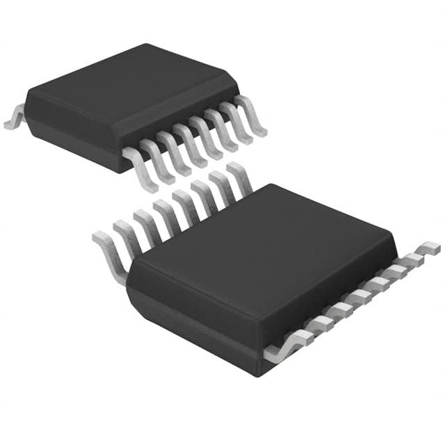
- Part No.:
- A5366CLWTR-T
- Manufacturer:
- Allegro MicroSystems
- Category:
- Sensor and Detector Interfaces
- Package:
- 16-SOIC (0.295", 7.50mm Width)
- Datasheet:
-
 A5366CLWTR-T.pdf
- Description:
- IC SMOKE DETECTOR PHOTO 16SOIC
- Quantity:
- Payment:

- Shipping:

Inventory:4,428
Please send an inquiry. Send us your inquiry, and we will respond immediately.
Product details
Overview
A5366CLWTR-T from Allegro MicroSystems is a BiCMOS photoelectric smoke detector IC with integrated photoamplifier, IR LED driver, piezoelectric horn interface, interconnect logic, and UL217/UL268-compliant temporal alarm pattern generation. It operates from 6–12 V, draws only 12 μA average standby current, supports up to 50-unit networking, and delivers calibrated chamber sensitivity monitoring for residential and commercial smoke alarms.
For engineers reviewing the A5366CLWTR-T datasheet, A5366CLWTR-T pinout, A5366CLWTR-T application, or A5366CLWTR-T equivalent, key selection considerations include its 16-pin SOICW package, internal strobe-regulated photoamplifier reference (VDD – 5 V), programmable gain via C1/C2 capacitors, UL-recognized low-battery detection, and three-stage speedup sensing architecture minimizing time-to-alarm while suppressing false triggers.
Technical Context
The A5366CLWTR-T integrates a variable-gain photoamplifier whose gain is set by external capacitors C1 (supervisory mode) and C2 (standby mode), with internal 10% gain boost during local alarm to reduce false triggering. Its internal oscillator drives synchronized STROBE, IRED, and LED timing with nominal periods of 10.4 ms (oscillator), 10 s (standby sampling), and 252 ms (test pulse).
It implements a deterministic interconnect protocol requiring three consecutive high samples on the I/O pin (≈95–137 ms minimum high time) to trigger remote alarm, plus built-in charge-dump circuitry for distributed capacitance immunity. The HUSH pin enables timer mode with reduced sensitivity, and TEST pin initiates push-to-test, diagnostic calibration, or timer reset-all without external microcontroller support.
Key Specifications
| Parameter | Value and Actual Design Meaning |
|---|---|
| Supply Voltage | 6–12 V - Enables direct operation from 9 V alkaline or 12 V sealed lead-acid batteries without regulation. |
| Standby Current | 12 μA typical - Achieved via 100 μs smoke-sensing bursts every 10 s, maximizing battery life in battery-powered alarms. |
| Operating Temp | –25°C to +75°C - Rated for indoor residential and commercial environments including attics and garages. |
| UL Recognition | UL217 & UL268 per file #S2113 - Certified for use in listed photoelectric smoke alarms meeting U.S. safety standards. |
| Oscillator Period | 9.4–11.5 ms - Sets base timing for STROBE, IRED, LED, and horn outputs; adjustable via OSC CAP and TIMING RES pins. |
| Interconnect Capacity | Up to 50 units - Uses open-drain I/O pin with internal NMOS charge dump for noise-immune daisy-chaining. |
| Horn Drive | HORN1/HORN2/FEEDBACK - Direct interface to self-resonant piezoelectric transducers generating UL-compliant temporal pattern (0.5 s on / 0.5 s off ×3, then 1.5 s off). |
Pinout & Package
Package: 16-pin SOICW (suffix LW), Pb-free with 100% matte-tin leadframe plating, JEDEC-standard footprint (MS-013AA), RθJA = 48°C/W on 4-layer PCB.
| Pin/Terminal | Circuit Role | Design Meaning |
|---|---|---|
| 1 C1 | Photoamplifier gain capacitor (supervisory) | Sets high gain (Ae = 1 + C1/10, C1 in pF) during push-to-test and chamber monitor; max 0.1 μF. |
| 2 C2 | Photoamplifier gain capacitor (standby) | Sets low gain during standby; increases ~10% after local alarm; requires series resistor. |
| 3 DETECT | Photodiode input | Zero-bias cathode connection; requires shunt resistor; sensitive to scattered IR light from smoke particles. |
| 4 STROBE | Strobed reference voltage output | Provides regulated VDD – 5 V reference for photoamplifier low-side; active only during sensing windows. |
| 5 VDD | Positive supply | 6–12 V input; powers all internal circuits; low-battery threshold at 6.9–7.5 V. |
| 6 IRED | IR LED driver output | Pulsed NPN base drive (2.85–3.35 V, –6 mA); inactive during horn/LED activation to minimize noise coupling. |
| 7 I/O | Interconnect input/output | Open-drain bidirectional node; samples every 42 ms; requires external series resistor to other detectors. |
| 8 HORN1 | Piezo transducer electrode drive | Connects to metal support electrode; works with HORN2 and FEEDBACK to generate resonant tone. |
| 9 HORN2 | Piezo transducer complementary drive | Connects to ceramic electrode; complements HORN1 for self-resonant oscillation. |
| 10 FEEDBACK | Piezo feedback input | Connects to feedback electrode; must tie to VSS if unused. |
| 11 LED | Visible LED driver | Open-drain NMOS; blinks every 0.5 s during local alarm; applies load for low-battery test. |
| 12 OSC CAP | Oscillator capacitor connection | With parallel resistor, sets clock low time (Tlow = 0.693 × ROSCCAP × COSCCAP). |
| 13 TIMING RES | Oscillator timing resistor | With OSC CAP, sets clock high time/IRED pulse width (Thigh = 0.693 × RTIMINGRES × COSCCAP). |
| 14 VSS | Negative supply | Ground reference for all analog and digital circuitry; common return for photodiode, IRED, horn, and LED. |
| 15 HUSH | Timer mode enable/reference | Internal pull-down; >1.5 V enables 10-minute hush mode; sets reduced sensitivity comparator reference during timer. |
| 16 TEST | Mode control input | Internal pull-down; high voltage initiates push-to-test; negative current (>400 μA) enters diagnostic calibration mode. |
Key Features
| Feature | Design Value |
|---|---|
| Three-stage speedup sensing | Reduces time-to-alarm by dynamically shortening STROBE/IRED intervals after first smoke detection, while requiring two consecutive degraded sensitivity cycles before chirp warning. |
| Self-contained interconnect logic | Eliminates need for external microcontroller or bus transceiver; supports 50-unit daisy-chain with built-in noise filtering and charge-dump recovery. |
| Programmable photoamplifier gain | Independent C1/C2 capacitor selection allows precise tuning of chamber sensitivity for different optical designs-no trimming resistors or firmware required. |
| UL-compliant temporal horn pattern | Internally generates exact NFPA72/ISO8201 temporal-3 pattern (0.5/0.5/0.5/0.5/0.5/1.5 s) on HORN1/HORN2 without external timing components. |
| Integrated low-battery and chamber health monitoring | Automatically runs periodic tests every ~43 s: LED flash indicates standby; chirp + LED flash = low battery; chirp offset from LED = degraded chamber. |
Applications
| Residential Smoke Alarms | Commercial Ceiling-Mounted Detectors |
|---|---|
|
Use Scenario: Battery-powered ceiling-mounted unit in bedrooms or hallways, interconnected with up to 49 other units across multiple floors. IC Role / Device Role / Timing Role: Central signal processor managing photoamplifier gain, IR pulsing, inter-unit communication, and UL-compliant horn/LED signaling. Use Value: Enables 10+ year battery life via 12 μA standby current and eliminates need for external microcontroller or timing ICs. |
Use Scenario: Hardwired 12 V smoke detector in office buildings or hotels, with optional battery backup and centralized alarm reporting. IC Role / Device Role / Timing Role: Standalone smoke sensing engine providing chamber sensitivity calibration, hush mode, and fault diagnostics without host MCU. Use Value: Reduces BOM count by integrating piezo driver, LED driver, interconnect logic, and UL-certified alarm pattern generator. |
| Interconnected Multi-Unit Systems | Smoke Detector Calibration & Test Platforms |
|
Use Scenario: Retrofit installation where existing detectors are upgraded with A5366CLWTR-T-based modules to add networking capability. IC Role / Device Role / Timing Role: Interconnect node implementing deterministic I/O arbitration and noise-immune alarm propagation across legacy wiring. Use Value: Supports up to 50-unit networks using simple twisted-pair wiring; no protocol stack or network configuration required. |
Use Scenario: Factory calibration station verifying chamber sensitivity, low-battery response, and horn output timing before final assembly. IC Role / Device Role / Timing Role: Enters diagnostic mode via TEST pin current injection, reconfiguring pins (e.g., HORN1 as integrator output) for automated test verification. Use Value: Eliminates need for external test equipment; enables pass/fail validation of photochamber performance using only the A5366CLWTR-T itself. |
Equivalent & Alternatives
The following parts are listed as comparable options for similar photoelectric smoke detector IC applications.
| Alternative Part | Technical Difference | Application Difference | Selection Advice |
|---|---|---|---|
| ISL28134IRZ-T7A | Single-channel precision op-amp with rail-to-rail I/O and 10 nV/√Hz noise; no integrated smoke logic, oscillator, or horn drive. | Requires full custom design of gain stages, timing, interconnect, and alarm generation; not UL-recognized. | Select only when full analog signal chain customization is needed and certification responsibility lies with end manufacturer. |
| SM555CDR | General-purpose timer IC; lacks photoamplifier, IRED driver, interconnect logic, UL-compliant horn pattern, or low-battery detection. | Cannot implement smoke detection algorithm or meet UL217 timing/sensitivity requirements without extensive external circuitry. | Use only for non-certified prototyping or auxiliary timing functions-not as a drop-in replacement for A5366CLWTR-T. |
Compared with ISL28134IRZ-T7A and SM555CDR, the A5366CLWTR-T delivers complete, UL-recognized smoke detection functionality in a single IC-including calibrated photoamplifier gain control, deterministic interconnect, temporal horn pattern, and autonomous chamber health monitoring-reducing design cycle time and certification risk.
Availability
A5366CLWTR-T is available at Aetrix Electronics and suitable for residential fire safety systems, commercial building alarm networks, and battery-powered smoke detector manufacturing requiring stable component supply and long-lifecycle support.
Supply support for A5366CLWTR-T includes scheduled delivery planning, volume procurement assistance, BOM continuity management, traceable sourcing, and lifecycle availability coordination for OEM customers, industrial embedded developers, connected-device designers, and electronics production programs.
Manufacturer
Allegro MicroSystems is a U.S.-based semiconductor company specializing in magnetic sensing, power ICs, and safety-critical sensor interfaces, with decades of experience in smoke detector ASICs.
The A5366 product line was designed specifically for photoelectric smoke alarms requiring UL217/UL268 recognition, low-power operation, and integrated interconnect-eliminating reliance on discrete op-amps, timers, and microcontrollers.
FAQ
What is the operating voltage range for the A5366CLWTR-T?
The A5366CLWTR-T operates from 6 V to 12 V referenced to VSS. This range supports standard 9 V alkaline batteries and 12 V backup supplies commonly used in residential and commercial smoke alarms. The device includes an internal low-battery detection circuit that triggers a warning chirp when VDD falls below 6.9–7.5 V, ensuring reliable end-of-life indication without external components.
How does the A5366CLWTR-T achieve UL217 and UL268 recognition?
The A5366CLWTR-T is UL Recognized under file #S2113 for use in smoke alarms complying with UL217 (residential) and UL268 (commercial) standards. Recognition covers its integrated temporal horn pattern generation, three-stage speedup sensing algorithm, chamber sensitivity monitoring, and deterministic interconnect logic-all validated per UL test protocols. The IC itself is not a certified alarm but enables full compliance when implemented per Allegro's reference design and layout guidelines.
What is the function of the C1 and C2 pins on the A5366CLWTR-T?
On the A5366CLWTR-T, C1 sets photoamplifier gain during push-to-test and chamber monitor modes (high-gain supervisory), while C2 sets gain during standby (low-gain). Gain is calculated as Ae = 1 + C/10 (C in pF), with C1 typically 0.047 μF and C2 typically 4700 pF. C2 also receives a 10% internal gain boost after local alarm detection to suppress false triggers, and both capacitors require careful layout to avoid noise coupling into the DETECT path.
Can the A5366CLWTR-T drive a piezoelectric horn directly?
Yes, the A5366CLWTR-T directly drives self-resonant piezoelectric horns using its HORN1, HORN2, and FEEDBACK pins. These outputs generate the UL-compliant temporal-3 pattern (0.5 s on / 0.5 s off ×3, then 1.5 s off) without external timing components. The FEEDBACK pin must be connected to the horn's feedback electrode; if unused, it must be tied to VSS. External passive components (e.g., 8.2 kΩ resistor) are required per Allegro's typical application diagram.
How does the interconnect feature work on the A5366CLWTR-T?
The A5366CLWTR-T uses its open-drain I/O pin to interconnect up to 50 units on a shared bus. When any unit detects smoke, it drives I/O high, and all connected units sample this signal every 42 ms. An alarm requires three consecutive high samples plus one additional cycle (≈95–137 ms total high time), providing strong noise immunity. Internal NMOS charge-dump circuitry clears distributed bus capacitance after alarm events, ensuring reliable multi-unit synchronization without external transceivers.
A5366CLWTR-T Specifications
- Product attributes
- Attribute value
- Manufacturer:
- Allegro MicroSystems
- Package/Case:
- 16-SOIC (0.295", 7.50mm Width)
- Series:
- -
- Packaging:
- Tape & Reel (TR)
- Product Status:
- Not For New Designs
- Programmable:
- Not Verified
- Type:
- Smoke Detector
- Input Type:
- Photoelectric
- Output Type:
- Voltage
- Current - Supply:
- 12 mA
- Operating Temperature:
- -25°C ~ 75°C
- Grade:
- -
- Qualification:
- -
- Mounting Type:
- Surface Mount
- Supplier Device Package:
- 16-SOIC
A5366CLWTR-T FAQ
1.How can I place an order for A5366CLWTR-T through Aetrix?
Please submit a Request for Quotation (RFQ) for A5366CLWTR-T on Aetrix. Our sales agent will provide a competitive quotation and guide you through the order confirmation once you accept the terms.
2.Are the price and stock information for A5366CLWTR-T reliable?
The price and inventory of A5366CLWTR-T are updated periodically and may fluctuate due to market conditions. Stock and pricing data are typically refreshed every 24 hours. Quotation validity for A5366CLWTR-T is usually 5 days.
3.What payment methods are accepted for A5366CLWTR-T?
We accept Wire Transfer, PayPal, Credit Card, Western Union, MoneyGram, and Escrow for A5366CLWTR-T transactions.
Note: Certain payment methods may incur a processing fee.
4.How is shipping managed for A5366CLWTR-T?
A5366CLWTR-T orders can be shipped via leading logistics carriers, including DHL, UPS, FedEx, TNT, or Registered Mail.
Once your A5366CLWTR-T order is processed, you will receive an email with the shipment details and tracking number.
Note: Tracking information may take up to 24 hours to appear. Express delivery typically takes 3–5 business days.
5.How can I obtain technical support or documentation for A5366CLWTR-T?
For technical support, including A5366CLWTR-T datasheets, pinout diagrams, or application guidance, please contact our engineering support team. They can provide detailed documentation and assistance for your A5366CLWTR-T requirements.
6.How does Aetrix verify that A5366CLWTR-T is sourced from the original manufacturer or authorized distributors?
All A5366CLWTR-T products on Aetrix are procured from qualified distributors and authorized channels. Our dedicated quality assurance team conducts strict verification, including traceability checks and, if necessary, third-party testing. This ensures that A5366CLWTR-T meets industry standards.
7.What is the process for return or replacement of A5366CLWTR-T?
All A5366CLWTR-T units undergo pre-shipment inspection (PSI). If there is an issue with A5366CLWTR-T, returns or replacements are accepted under the following conditions:
1.Quantity discrepancies, incorrect items, or visible external defects (such as breakage or corrosion), acknowledged by Aetrix.
2.The issue is reported within 90 days of delivery.
3.The A5366CLWTR-T part is unused and in its original packaging.
Return procedure for A5366CLWTR-T:
1.Submit a request within 90 days.
2.Obtain a Return Material Authorization (RMA) from Aetrix.
A5366CLWTR-T Tags

-
RE46C100S8TF
Microchip Technology

-
XTR111AIDRCR
Texas Instruments

-
XTR111AIDGQR
Texas Instruments

-
XTR117AIDGKR
Texas Instruments
-
XTR111AIDGQT
Texas Instruments

-
XTR115UA/2K5
Texas Instruments

-
MAX14626ETT+T
Analog Devices Inc./Maxim Integrated
-
XTR116UA/2K5
Texas Instruments
-
XTR115U/2K5
Texas Instruments
-
XTR116U/2K5
Texas Instruments

-
PGA308AIDGSR
Texas Instruments

-
XTR300AIRGWR
Texas Instruments
Tech Hub

A practical engineering and sourcing framework covering lifecycle verification, lifetime-buy calculations, replacement qualification, supplier checks and counterfeit-risk controls.

TTL and CMOS logic families differ in thresholds, loading, output drive, power and timing. This engineering guide compares 74HC and 74HCT, calculates noise margins and checks 3.3 V/5 V compatibility.

A practical engineering guide to 3.3V and 5V logic compatibility, input thresholds, resistor dividers, translator ICs, MOSFET level shifting, I2C pull-ups, timing limits and power-sequencing risks.

The 74HC595 uses push-pull logic outputs, while the TPIC6B595 uses 50 V open-drain DMOS sinks for higher-power loads. This guide compares timing, current limits, 3.3 V interfacing, load wiring, thermal…

The 74HC595 converts serial data into eight stable parallel outputs. This guide covers pin functions, shift and storage timing, OE and MR behavior, drive-current limits, cascading, voltage compatibilit…

A technical comparison of level-sensitive latches and edge-triggered flip-flops, covering timing windows, setup and hold limits, master–slave operation, time borrowing, race-through, HDL inference and…

A D latch stores one bit while Enable controls when data can pass. This reference covers gate-level operation, truth tables, transparency, setup and hold timing, LE versus OE, common ICs and practical …

An SR latch stores one bit through cross-coupled feedback. This engineering reference covers NOR and NAND implementations, truth tables, forbidden-state recovery, gated operation, switch debouncing, fa…

Latch circuits retain one bit through feedback. This technical reference covers SR and D latches, truth tables, transparency, timing limits, latch-versus-flip-flop behavior, applications and common log…

An engineering guide to LED driver operation, constant-current and constant-voltage outputs, linear and switching topologies, dimming, IC selection, calculations, replacement compatibility, and fault c…


