
 My Inquiry
 My Account


Allegro MicroSystems A6217KLJTR-1-T
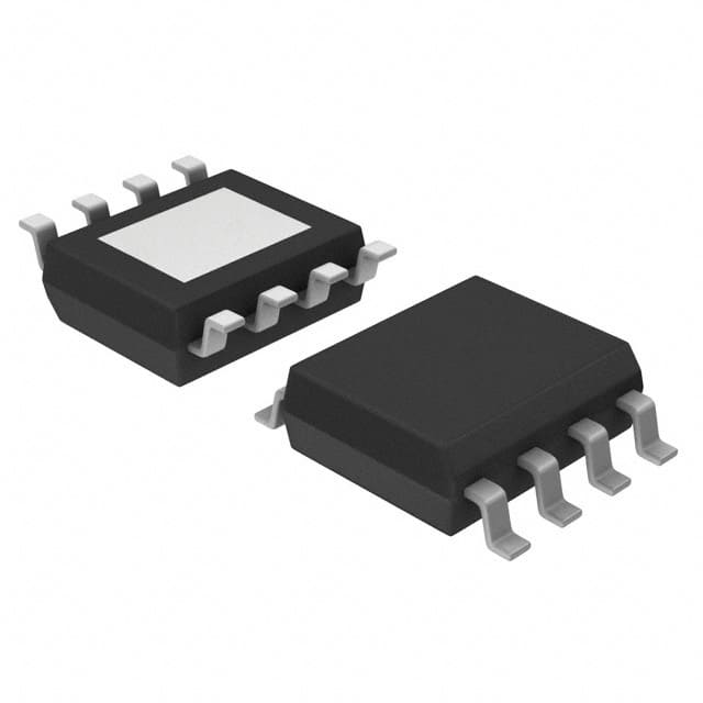
- Part No.:
- A6217KLJTR-1-T
- Manufacturer:
- Allegro MicroSystems
- Category:
- LED Drivers
- Package:
- 8-SOIC (0.154", 3.90mm Width) Exposed Pad
- Datasheet:
-
 A6217KLJTR-1-T.pdf
- Description:
- IC LED DRVR RGLTR PWM 1.5A 8SOIC
- Quantity:
- Payment:

- Shipping:

Inventory:5,900
Please send an inquiry. Send us your inquiry, and we will respond immediately.
Product details
Overview
A6217KLJTR-1-T from Allegro MicroSystems is an automotive-grade, constant-current PWM-dimmable buck LED driver IC with integrated high-side N-channel DMOS switch. It delivers 1.5 A true average output current across 6–48 V input, supports up to 2.2 MHz switching (dithered ±5%), and regulates LED string voltage automatically for optimal efficiency in single-string configurations. Used in daytime running lights and rear fog lamps.
For engineers reviewing the A6217KLJTR-1-T datasheet, A6217KLJTR-1-T pinout, A6217KLJTR-1-T application, or A6217KLJTR-1-T equivalent, key selection criteria include its AEC-Q100 qualification, 1.5 A max output current at full temperature range, SOICN-8 wettable flank package with exposed thermal pad, and direct logic-level PWM dimming via EN pin (100 Hz–2 kHz).
Technical Context
The A6217KLJTR-1-T employs fixed on-time, average current mode control with cycle-by-cycle current limiting. Its internal 5.3 V linear regulator powers gate drive circuitry, while dithered oscillator (±5% range, ~11 kHz modulation) reduces EMI peaks.
It integrates UVLO (5.3 V threshold, 150 mV hysteresis), thermal shutdown (165 °C, 25 °C hysteresis), and robust fault protection-including adjacent pin shorts, pin-to-GND shorts, and open/short detection on CS and SW nodes.
Key Specifications
| Parameter | Value and Actual Design Meaning |
|---|---|
| Max Output Current | 1.5 A over full operating temperature range (–40°C to +125°C junction) |
| Input Voltage Range | 6 V to 48 V - supports 12 V and 24 V automotive battery rails with transient tolerance |
| Switching Frequency | Programmable via RON; typical 1 MHz at RON = 73.2 kΩ, dithered ±5% to suppress EMI harmonics |
| Current Sense Threshold | 200 mV typical - sets LED current as iLED = 0.2 V / RSENSE, enabling precise external programming |
| Thermal Resistance | RθJA = 35 °C/W on 4-layer JEDEC PCB - enabled by exposed thermal pad in SOICN-8 (LJ) package |
| PWM Dimming Range | 100 Hz to 2 kHz input frequency; supports ≥1% dimming ratio with <50 µs minimum on-time |
| Shutdown Current | 1 µA typical - enables ultra-low power state during EN low >20 ms |
Pinout & Package
Package: 8-pin narrow SOIC (SOICN-8) with wettable flank leads and exposed thermal pad (suffix LJ); Pb-free, 100% matte-tin leadframe plating.
| Pin/Terminal | Circuit Role | Design Meaning |
|---|---|---|
| VIN (pins 1,2) | Supply voltage input | Accepts 6–48 V DC; connects to bulk and ceramic input capacitors for stable rail |
| TON (pin 3) | On-time setting resistor terminal | Determines switching frequency via external RON between VIN and TON |
| EN (pin 4) | Enable / PWM dimming input | Logic-level compatible (VIH ≥ 1.8 V); directly accepts 100 Hz–2 kHz PWM for brightness control |
| CS (pin 5) | Current sense feedback | Monitors voltage across RSENSE; regulated at 200 mV for true average current control |
| VCC (pin 6) | Internal LDO output | 5.4 V typical regulated supply for internal circuitry; requires 0.1 µF decoupling to GND |
| GND (pin 7) | Ground reference | Primary signal and power return; connects to exposed thermal pad for thermal conduction |
| BOOT (pin 8) | Bootstrap gate drive | Charges high-side MOSFET gate driver; requires 0.1 µF ceramic capacitor to SW |
| SW (pin 9,10) | Switched output node | Drives external inductor and freewheeling diode; transitions rapidly between 0 V and VIN |
Key Features
| Feature | Design Value |
|---|---|
| AEC-Q100 Grade-1 qualified | Validated for automotive ambient temperatures (–40°C to +125°C) and stress testing per automotive reliability standard |
| Integrated high-side DMOS switch | RDS(on) = 0.25 Ω typical - eliminates need for external high-voltage switch and associated gate drive complexity |
| True average current regulation | Maintains consistent LED brightness independent of forward voltage drift or temperature variation across LED string |
| Dithered switching frequency | ±5% spread spectrum modulation at ~11 kHz - reduces peak EMI by distributing energy across narrow band |
| Robust fault protection suite | Detects and shuts down on pin-to-GND short, adjacent pin short, CS open/short, and SW overcurrent (>2.2 A for A6217-1 variant) |
Applications
| Daytime Running Lights (DRL) | Rear Fog Lights |
|---|---|
Use Scenario: Continuous 12–24 V automotive DRL operation requiring stable 1.5 A LED current under wide temperature and input voltage variation. IC Role / Device Role / Timing Role: Constant-current buck controller regulating single high-brightness LED string; manages dynamic load during cold crank (6 V) and load dump (48 V). Use Value: Maintains uniform luminance without thermal derating or brightness droop, leveraging 1.5 A rated output and 35 °C/W thermal resistance in SOICN-8 package. |
Use Scenario: High-intensity rear fog lamp in adverse weather, driven from 24 V commercial vehicle systems with strict EMC requirements. IC Role / Device Role / Timing Role: PWM-dimmable LED driver with dithered switching; enables compliance with UNECE R112 photometric stability and conducted emission limits. Use Value: ±5% frequency dithering reduces 1 MHz harmonic peaks by >10 dBµV, easing filter design and meeting CISPR 25 Class 3 limits without added ferrites. |
| Turn/Stop Lights | Dimmable Interior Map Lights |
Use Scenario: Dual-function turn/brake lamp where same LED array must flash at 1–4 Hz (turn) and sustain 1.5 A (brake), with fast startup response. IC Role / Device Role / Timing Role: Enable-controlled buck regulator with 70 µs startup delay; supports immediate reactivation during PWM dimming without full restart. Use Value: Eliminates visible latency between brake activation and full brightness-critical for safety-critical stop lamp response time (<100 ms). |
Use Scenario: Cabin map light with user-adjustable brightness via microcontroller-generated 200 Hz PWM signal. IC Role / Device Role / Timing Role: Direct logic-level EN pin interface accepting MCU GPIO; supports 1%–100% dimming with no external level-shifting or optocouplers. Use Value: Reduces BOM count by integrating dimming interface, eliminating external driver ICs or resistive dividers required by non-PWM-capable LED drivers. |
Equivalent & Alternatives
The following parts are listed as comparable options for similar constant-current buck LED driver applications.
| Alternative Part | Technical Difference | Application Difference | Selection Advice |
|---|---|---|---|
| AL8862SP-13 | Non-AEC-Q100; 1.2 A max output; no dithering; requires external bootstrap diode | Targeted at industrial/commercial lighting; lacks automotive thermal and EMC hardening | Choose for cost-sensitive non-automotive designs where 1.2 A and absence of dithering are acceptable |
| LM3409QMY/NOPB | AEC-Q100 Grade 1; 1.5 A max; no integrated MOSFET (external FET required); no dithering | Requires external high-side switch and gate driver; higher layout complexity and component count | Prefer when system-level thermal management demands discrete FET placement or when programmable current limit is needed beyond 1.5 A |
Compared with AL8862SP-13 and LM3409QMY/NOPB, the A6217KLJTR-1-T uniquely combines AEC-Q100 qualification, integrated 1.5 A switch, and ±5% dithering in a thermally enhanced SOICN-8 package-enabling drop-in automotive LED lighting designs with minimal external components and proven EMC performance.
Availability
A6217KLJTR-1-T is available at Aetrix Electronics and suitable for automotive lighting, daytime running lights, and rear fog lamps requiring stable component supply with AEC-Q100 assurance and long-term production continuity.
Supply support for A6217KLJTR-1-T includes scheduled delivery planning, volume procurement assistance, BOM continuity management, traceable sourcing, and lifecycle availability coordination for OEM customers, industrial embedded developers, connected-device designers, and electronics production programs.
Manufacturer
Allegro MicroSystems is a U.S.-based designer and manufacturer of high-performance power ICs and magnetic sensors, founded in 1989 and headquartered in Manchester, NH.
The A6217 product line delivers automotive-grade constant-current LED drivers optimized for safety-critical exterior lighting, emphasizing thermal robustness, EMI resilience, and functional safety-ready protection features.
FAQ
What is the maximum continuous output current of the A6217KLJTR-1-T?
The A6217KLJTR-1-T is rated for 1.5 A maximum true average output current across its full operating junction temperature range of –40°C to +125°C. This is confirmed in the Selection Guide and Electrical Characteristics table, where the A6217-1 variant specifies ISWLIM min/typ/max values of 1.9/2.2/2.7 A, supporting 1.5 A continuous operation with margin. The A6217KLJTR-1-T part number explicitly maps to the "A6217-1" variant per Allegro's packaging and current rating documentation.
Does the A6217KLJTR-1-T require an external MOSFET?
No, the A6217KLJTR-1-T integrates a high-side N-channel DMOS switch with RDS(on) = 0.25 Ω typical, eliminating the need for an external MOSFET. This is stated in the DESCRIPTION section ("integrates a high-side N-channel DMOS switch") and confirmed in the ELECTRICAL CHARACTERISTICS table under "Buck Switch On-Resistance." The functional block diagram also shows the internal "Buck Switch" and "IC and Driver" blocks feeding directly to the SW pin.
What package type does the A6217KLJTR-1-T use, and is it RoHS compliant?
The A6217KLJTR-1-T uses the 8-pin narrow SOIC (SOICN-8) package with wettable flank leads and an exposed thermal pad (suffix LJ). It is lead (Pb) free and features 100% matte-tin leadframe plating, satisfying RoHS Directive 2011/65/EU requirements. This is documented in the PACKAGE section and confirmed in the Selection Guide, which lists "8-pin SOICN with exposed thermal pad" for A6217KLJTR-1-T.
How is PWM dimming implemented on the A6217KLJTR-1-T?
PWM dimming on the A6217KLJTR-1-T is implemented directly via the EN pin, which accepts logic-level signals from 100 Hz to 2 kHz. The IC interprets the duty cycle of this signal to proportionally control LED brightness, with no external components required. The Functional Description confirms EN is "high-voltage tolerant" and "logic-level compatible," and Figure 2 demonstrates clean PWM waveforms at 200 Hz with 50% and 2% duty cycles.
Is the A6217KLJTR-1-T qualified to AEC-Q100, and what grade does it meet?
Yes, the A6217KLJTR-1-T is AEC-Q100 qualified and meets Grade 1 requirements (operating ambient temperature range –40°C to +125°C). This is explicitly listed under "FEATURES AND BENEFITS" and reinforced in the Selection Guide and Functional Description sections. The device's thermal shutdown threshold (165°C) and hysteresis (25°C), along with RθJA = 35 °C/W, support reliable operation within Grade 1 ambient limits.
A6217KLJTR-1-T Specifications
- Product attributes
- Attribute value
- Manufacturer:
- Allegro MicroSystems
- Series:
- -
- Package/Case:
- 8-SOIC (0.154", 3.90mm Width) Exposed Pad
- Packaging:
- Tape & Reel (TR)
- Product Status:
- Active
- Type:
- DC DC Regulator
- Topology:
- Step-Down (Buck)
- Internal Switch(s):
- Yes
- Number of Outputs:
- 1
- Voltage - Supply (Min):
- 6V
- Voltage - Supply (Max):
- 48V
- Voltage - Output:
- -
- Current - Output / Channel:
- 1.5A
- Frequency:
- -
- Dimming:
- PWM
- Applications:
- -
- Operating Temperature:
- -40°C ~ 125°C (TJ)
- Grade:
- Automotive
- Qualification:
- AEC-Q100
- Mounting Type:
- Surface Mount
- Supplier Device Package:
- 8-SOIC-EP
A6217KLJTR-1-T FAQ
1.How can I place an order for A6217KLJTR-1-T through Aetrix?
Please submit a Request for Quotation (RFQ) for A6217KLJTR-1-T on Aetrix. Our sales agent will provide a competitive quotation and guide you through the order confirmation once you accept the terms.
2.Are the price and stock information for A6217KLJTR-1-T reliable?
The price and inventory of A6217KLJTR-1-T are updated periodically and may fluctuate due to market conditions. Stock and pricing data are typically refreshed every 24 hours. Quotation validity for A6217KLJTR-1-T is usually 5 days.
3.What payment methods are accepted for A6217KLJTR-1-T?
We accept Wire Transfer, PayPal, Credit Card, Western Union, MoneyGram, and Escrow for A6217KLJTR-1-T transactions.
Note: Certain payment methods may incur a processing fee.
4.How is shipping managed for A6217KLJTR-1-T?
A6217KLJTR-1-T orders can be shipped via leading logistics carriers, including DHL, UPS, FedEx, TNT, or Registered Mail.
Once your A6217KLJTR-1-T order is processed, you will receive an email with the shipment details and tracking number.
Note: Tracking information may take up to 24 hours to appear. Express delivery typically takes 3–5 business days.
5.How can I obtain technical support or documentation for A6217KLJTR-1-T?
For technical support, including A6217KLJTR-1-T datasheets, pinout diagrams, or application guidance, please contact our engineering support team. They can provide detailed documentation and assistance for your A6217KLJTR-1-T requirements.
6.How does Aetrix verify that A6217KLJTR-1-T is sourced from the original manufacturer or authorized distributors?
All A6217KLJTR-1-T products on Aetrix are procured from qualified distributors and authorized channels. Our dedicated quality assurance team conducts strict verification, including traceability checks and, if necessary, third-party testing. This ensures that A6217KLJTR-1-T meets industry standards.
7.What is the process for return or replacement of A6217KLJTR-1-T?
All A6217KLJTR-1-T units undergo pre-shipment inspection (PSI). If there is an issue with A6217KLJTR-1-T, returns or replacements are accepted under the following conditions:
1.Quantity discrepancies, incorrect items, or visible external defects (such as breakage or corrosion), acknowledged by Aetrix.
2.The issue is reported within 90 days of delivery.
3.The A6217KLJTR-1-T part is unused and in its original packaging.
Return procedure for A6217KLJTR-1-T:
1.Submit a request within 90 days.
2.Obtain a Return Material Authorization (RMA) from Aetrix.
A6217KLJTR-1-T Tags

-
BCR402RE6327HTSA1
Infineon Technologies

-
BCR430UXTSA2
Infineon Technologies

-
BCR420UE6433HTMA1
Infineon Technologies
-
BCR420UE6327HTSA1
Infineon Technologies
-
BCR421UE6327HTSA1
Infineon Technologies

-
LYT1604D-TL
Power Integrations

-
HV9910CLG-G
Microchip Technology

-
CL2N8-G
Microchip Technology

-
BCR420UW6-7
Diodes Incorporated
-
BCR421UW6-7
Diodes Incorporated

-
BCR420UFD-7
Diodes Incorporated
-
BCR421UFD-7
Diodes Incorporated
Tech Hub

A practical engineering and sourcing framework covering lifecycle verification, lifetime-buy calculations, replacement qualification, supplier checks and counterfeit-risk controls.

TTL and CMOS logic families differ in thresholds, loading, output drive, power and timing. This engineering guide compares 74HC and 74HCT, calculates noise margins and checks 3.3 V/5 V compatibility.

A practical engineering guide to 3.3V and 5V logic compatibility, input thresholds, resistor dividers, translator ICs, MOSFET level shifting, I2C pull-ups, timing limits and power-sequencing risks.

The 74HC595 uses push-pull logic outputs, while the TPIC6B595 uses 50 V open-drain DMOS sinks for higher-power loads. This guide compares timing, current limits, 3.3 V interfacing, load wiring, thermal…

The 74HC595 converts serial data into eight stable parallel outputs. This guide covers pin functions, shift and storage timing, OE and MR behavior, drive-current limits, cascading, voltage compatibilit…

A technical comparison of level-sensitive latches and edge-triggered flip-flops, covering timing windows, setup and hold limits, master–slave operation, time borrowing, race-through, HDL inference and…

A D latch stores one bit while Enable controls when data can pass. This reference covers gate-level operation, truth tables, transparency, setup and hold timing, LE versus OE, common ICs and practical …

An SR latch stores one bit through cross-coupled feedback. This engineering reference covers NOR and NAND implementations, truth tables, forbidden-state recovery, gated operation, switch debouncing, fa…

Latch circuits retain one bit through feedback. This technical reference covers SR and D latches, truth tables, transparency, timing limits, latch-versus-flip-flop behavior, applications and common log…

An engineering guide to LED driver operation, constant-current and constant-voltage outputs, linear and switching topologies, dimming, IC selection, calculations, replacement compatibility, and fault c…


