
 My Inquiry
 My Account


Allegro MicroSystems A6269KLJTR-T
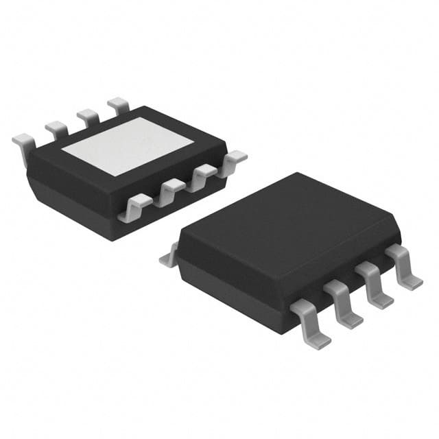
- Part No.:
- A6269KLJTR-T
- Manufacturer:
- Allegro MicroSystems
- Category:
- LED Drivers
- Package:
- 8-SOIC (0.154", 3.90mm Width) Exposed Pad
- Datasheet:
-
 A6269KLJTR-T.pdf
- Description:
- IC LED DRVR LIN PWM 200MA 8SOIC
- Quantity:
- Payment:

- Shipping:

Inventory:2,053
Please send an inquiry. Send us your inquiry, and we will respond immediately.
Product details
Overview
A6269KLJTR-T from Allegro MicroSystems is an AEC-Q100-qualified, linear, dual-channel automotive LED array driver providing programmable constant current up to 200 mA per channel with ±4% accuracy, 5% current matching between outputs, and integrated short-to-ground and thermal protection. It operates from 6–50 V supply and drives 1–3 LEDs per string in dome, map, and mood lighting systems.
For engineers reviewing the A6269KLJTR-T datasheet, A6269KLJTR-T pinout, A6269KLJTR-T application, or A6269KLJTR-T equivalent, key selection considerations include its 8-pin SOICN (LJ) package with exposed thermal pad, adjustable thermal foldback via THTH pin, PWM-enabled EN input, debounced SW toggle control, and automotive-grade reliability for interior lighting.
Technical Context
The A6269KLJTR-T integrates two matched linear current regulators with independent LA1/LA2 anode outputs, each sourcing up to −200 mA with dropout voltage as low as 660 mV at −80 mA. Its thermal monitor dynamically reduces output current above TJM (adjustable 95–130°C) at −2.5%/°C slope until overtemperature shutdown at 170°C.
Short detection disables individual outputs when LAx falls below 1.2 V (short-to-ground), resuming regulation automatically upon fault removal. The device supports direct PWM dimming via EN and mechanical on/off toggling via SW, with 30 ms debounce and internal 100 µA pull-up.
Key Specifications
| Parameter | Value and Actual Design Meaning |
|---|---|
| LED Outputs | 2 independent channels, each sourcing up to −200 mA with ±4% accuracy |
| Supply Voltage Range | 6–50 V - supports full automotive battery range including load dump |
| Current Matching | Better than 5% between LA1 and LA2 without ballast resistors |
| Thermal Protection | Adjustable activation threshold (95–130°C) with −2.5%/°C current reduction slope |
| Short Detection | LAx disable at <1.2 V; auto-resume when voltage rises >1.9 V |
| Package | 8-pin SOICN (LJ), 3.9 × 4.9 mm with exposed thermal pad (RθJP = 2°C/W) |
| Operating Temperature | −40°C to +125°C ambient - qualified per AEC-Q100 Grade 1 |
Pinout & Package
Package: 8-pin SOICN (LJ) with exposed thermal pad (PAD), 3.9 × 4.9 mm case size, lead-free with 100% matte tin plating. Designed for high-power dissipation on 4-layer PCBs (RθJA = 35°C/W).
| Pin/Terminal | Circuit Role | Design Meaning |
|---|---|---|
| 1 - THTH | Thermal threshold adjust | Resistor divider sets TJM (95–130°C); open = default TJM; GND = disable thermal monitor |
| 2 - IREF | Reference current input | 1.2 V reference node; RREF to GND sets output current (e.g., 167 Ω → 180 mA) |
| 3 - GND | Ground reference | Primary return path for control circuitry and current regulators |
| 4 - LA1 | LED anode output 1 | Sinks up to −200 mA; connects directly to first LED anode in string 1 |
| 5 - LA2 | LED anode output 2 | Sinks up to −200 mA; connects directly to first LED anode in string 2 |
| 6 - VIN | Power supply input | 6–50 V input for control logic and current regulators; bypass with 100 nF ceramic |
| 7 - EN | Enable input | Active-high logic input for direct PWM dimming; 150–350 mV hysteresis |
| 8 - SW | Debounced switch input | Pull-up to ~3 V; 30 ms debounce; ground toggle enables on/off state change |
| PAD | Exposed thermal pad | Internally connected to GND; requires soldered copper area for RθJP = 2°C/W |
Key Features
| Feature | Design Value |
|---|---|
| AEC-Q100 qualification | Grade 1 (−40°C to +125°C ambient) ensures reliability in automotive interior lighting |
| Dual matched current regulation | ±4% accuracy per channel and <5% inter-channel mismatch enable uniform brightness without ballast resistors |
| Configurable thermal foldback | THTH pin allows precise setting of current-reduction onset temperature (95–130°C) to match system thermal limits |
| Integrated short-to-ground protection | Per-output fault detection disables only affected channel, preserving operation of remaining LED string |
| Dual control interface | EN pin enables fast PWM dimming; SW pin provides robust mechanical toggle with 30 ms debounce |
Applications
| Dome Light Control | Map Light Dimming |
|---|---|
|
Use Scenario: Interior overhead lighting activated by door opening or vehicle ignition. IC Role / Device Role / Timing Role: Dual-channel constant-current driver powering two parallel LED strings with synchronized on/off and PWM dimming. Use Value: Ensures consistent luminance across both strings (≤5% mismatch) and survives 50 V load dump transients without derating. |
Use Scenario: Driver/passenger reading lights controlled by discrete push-button switches. IC Role / Device Role / Timing Role: SW-input-debounced on/off toggle controller with EN-enabled smooth PWM fade-in/fade-out. Use Value: Eliminates contact bounce artifacts and enables flicker-free dimming down to 100 Hz without external RC filtering. |
| Mood Lighting System | Space Lighting Module |
|
Use Scenario: Ambient cabin lighting with color-mixing via independently dimmed warm/cool white LEDs. IC Role / Device Role / Timing Role: Precision current source for two independent LED channels, each driven by separate PWM signals. Use Value: Maintains chromatic consistency under varying supply (6–16 V) due to tight current regulation (±4%) and low dropout (660 mV). |
Use Scenario: Overhead console lighting in commercial vehicles requiring extended thermal endurance. IC Role / Device Role / Timing Role: Thermally adaptive driver with THTH-configured foldback to sustain 200 mA/channel at 85°C ambient. Use Value: Prevents thermal runaway by reducing current at junction temperatures >115°C, enabling continuous operation where passive heatsinking is constrained. |
Equivalent & Alternatives
The following parts are listed as comparable options for similar LED driver applications.
| Alternative Part | Technical Difference | Application Difference | Selection Advice |
|---|---|---|---|
| A6261KLJTR-T | Single-channel, 200 mA output; no SW toggle input; identical thermal and short-protection features | Suitable only for single-string designs; lacks dual-output synchronization and independent channel control | Select when cost-sensitive single-string lighting suffices and SW functionality is unnecessary |
| A6262KLPTR-T | 2-channel, 200 mA/channel; 16-pin TSSOP package (LP); includes diagnostic flag output not present in A6269KLJTR-T | Requires larger PCB footprint and different thermal layout; diagnostic output enables fault reporting in centralized lighting controllers | Choose for new designs needing fault status feedback and higher pin-count flexibility, accepting larger package size |
Compared with A6269KLJTR-T, A6261KLJTR-T reduces channel count and control interface while maintaining core protection; A6262KLPTR-T adds diagnostics and uses a larger package, trading compactness for system-level monitoring capability.
Availability
A6269KLJTR-T is available at Aetrix Electronics and suitable for automotive dome light, map light, and mood lighting applications requiring stable component supply, AEC-Q100 compliance, and thermal resilience in harsh environments.
Supply support for A6269KLJTR-T includes scheduled delivery planning, volume procurement assistance, BOM continuity management, traceable sourcing, and lifecycle availability coordination for OEM customers, industrial embedded developers, connected-device designers, and electronics production programs.
Manufacturer
Allegro MicroSystems is a U.S.-based semiconductor company specializing in magnetic sensing, power ICs, and precision motion control solutions for automotive and industrial markets.
The A6269 product line delivers AEC-Q100-qualified linear LED drivers optimized for interior automotive lighting, emphasizing thermal adaptability, fault resilience, and dual-control interface flexibility.
FAQ
What is the maximum continuous LED current per channel for the A6269KLJTR-T?
The A6269KLJTR-T delivers up to −200 mA per channel (LA1 and LA2) under specified conditions: VIN ≥ 7 V, TA ≤ 125°C, and adequate thermal management. At IREF = 8 mA, typical output is −200 mA; maximum rated is −220 mA with IREF = 9.2 mA. Current is reduced above TJM due to thermal foldback.
How does the THTH pin configure thermal protection on the A6269KLJTR-T?
The THTH pin on the A6269KLJTR-T sets the thermal monitor activation temperature (TJM) via external resistor networks. Open-circuit yields TJM = 115°C (typ); connecting to GND disables thermal foldback; pulling up/down adjusts TJM between 95°C and 130°C. This directly controls the onset of current reduction to prevent thermal runaway.
Can the A6269KLJTR-T drive more than three LEDs per string?
No - the A6269KLJTR-T is optimized for 1–3 LEDs per string. Driving more than three increases forward voltage beyond practical dropout margins, especially at low VIN (e.g., 6 V). For 4+ LED strings, higher supply or switching architecture is required; the A6269KLJTR-T's minimum dropout is 660 mV at −80 mA, limiting usable headroom.
What happens during a short-to-ground fault on LA1 of the A6269KLJTR-T?
When LA1 is shorted to ground, the A6269KLJTR-T detects voltage <1.2 V and disables only LA1 output while maintaining full regulation on LA2. A small monitoring current (−1.6 mA typ) sustains fault detection; once LA1 voltage rises >1.9 V, regulation resumes automatically - no reset or intervention required.
Is the A6269KLJTR-T still recommended for new designs?
No - the A6269KLJTR-T is discontinued per Allegro documentation dated December 28, 2019. It is not recommended for new designs. Allegro recommends A6261KLJTR-T (single-channel) or A6262KLPTR-T (dual-channel with diagnostics) as transition paths. Samples are no longer available.
A6269KLJTR-T Specifications
- Product attributes
- Attribute value
- Manufacturer:
- Allegro MicroSystems
- Series:
- -
- Package/Case:
- 8-SOIC (0.154", 3.90mm Width) Exposed Pad
- Packaging:
- Tape & Reel (TR)
- Product Status:
- Obsolete
- Type:
- Linear
- Topology:
- -
- Internal Switch(s):
- Yes
- Number of Outputs:
- 2
- Voltage - Supply (Min):
- 6V
- Voltage - Supply (Max):
- 50V
- Voltage - Output:
- -
- Current - Output / Channel:
- 200mA
- Frequency:
- -
- Dimming:
- PWM
- Applications:
- -
- Operating Temperature:
- -40°C ~ 125°C (TA)
- Grade:
- Automotive
- Qualification:
- AEC-Q100
- Mounting Type:
- Surface Mount
- Supplier Device Package:
- 8-SOIC-EP
A6269KLJTR-T FAQ
1.How can I place an order for A6269KLJTR-T through Aetrix?
Please submit a Request for Quotation (RFQ) for A6269KLJTR-T on Aetrix. Our sales agent will provide a competitive quotation and guide you through the order confirmation once you accept the terms.
2.Are the price and stock information for A6269KLJTR-T reliable?
The price and inventory of A6269KLJTR-T are updated periodically and may fluctuate due to market conditions. Stock and pricing data are typically refreshed every 24 hours. Quotation validity for A6269KLJTR-T is usually 5 days.
3.What payment methods are accepted for A6269KLJTR-T?
We accept Wire Transfer, PayPal, Credit Card, Western Union, MoneyGram, and Escrow for A6269KLJTR-T transactions.
Note: Certain payment methods may incur a processing fee.
4.How is shipping managed for A6269KLJTR-T?
A6269KLJTR-T orders can be shipped via leading logistics carriers, including DHL, UPS, FedEx, TNT, or Registered Mail.
Once your A6269KLJTR-T order is processed, you will receive an email with the shipment details and tracking number.
Note: Tracking information may take up to 24 hours to appear. Express delivery typically takes 3–5 business days.
5.How can I obtain technical support or documentation for A6269KLJTR-T?
For technical support, including A6269KLJTR-T datasheets, pinout diagrams, or application guidance, please contact our engineering support team. They can provide detailed documentation and assistance for your A6269KLJTR-T requirements.
6.How does Aetrix verify that A6269KLJTR-T is sourced from the original manufacturer or authorized distributors?
All A6269KLJTR-T products on Aetrix are procured from qualified distributors and authorized channels. Our dedicated quality assurance team conducts strict verification, including traceability checks and, if necessary, third-party testing. This ensures that A6269KLJTR-T meets industry standards.
7.What is the process for return or replacement of A6269KLJTR-T?
All A6269KLJTR-T units undergo pre-shipment inspection (PSI). If there is an issue with A6269KLJTR-T, returns or replacements are accepted under the following conditions:
1.Quantity discrepancies, incorrect items, or visible external defects (such as breakage or corrosion), acknowledged by Aetrix.
2.The issue is reported within 90 days of delivery.
3.The A6269KLJTR-T part is unused and in its original packaging.
Return procedure for A6269KLJTR-T:
1.Submit a request within 90 days.
2.Obtain a Return Material Authorization (RMA) from Aetrix.
A6269KLJTR-T Tags

-
BCR402RE6327HTSA1
Infineon Technologies

-
BCR430UXTSA2
Infineon Technologies

-
BCR420UE6433HTMA1
Infineon Technologies
-
BCR420UE6327HTSA1
Infineon Technologies
-
BCR421UE6327HTSA1
Infineon Technologies

-
LYT1604D-TL
Power Integrations

-
HV9910CLG-G
Microchip Technology

-
CL2N8-G
Microchip Technology

-
BCR420UW6-7
Diodes Incorporated
-
BCR421UW6-7
Diodes Incorporated

-
BCR420UFD-7
Diodes Incorporated
-
BCR421UFD-7
Diodes Incorporated
Tech Hub

A practical engineering and sourcing framework covering lifecycle verification, lifetime-buy calculations, replacement qualification, supplier checks and counterfeit-risk controls.

TTL and CMOS logic families differ in thresholds, loading, output drive, power and timing. This engineering guide compares 74HC and 74HCT, calculates noise margins and checks 3.3 V/5 V compatibility.

A practical engineering guide to 3.3V and 5V logic compatibility, input thresholds, resistor dividers, translator ICs, MOSFET level shifting, I2C pull-ups, timing limits and power-sequencing risks.

The 74HC595 uses push-pull logic outputs, while the TPIC6B595 uses 50 V open-drain DMOS sinks for higher-power loads. This guide compares timing, current limits, 3.3 V interfacing, load wiring, thermal…

The 74HC595 converts serial data into eight stable parallel outputs. This guide covers pin functions, shift and storage timing, OE and MR behavior, drive-current limits, cascading, voltage compatibilit…

A technical comparison of level-sensitive latches and edge-triggered flip-flops, covering timing windows, setup and hold limits, master–slave operation, time borrowing, race-through, HDL inference and…

A D latch stores one bit while Enable controls when data can pass. This reference covers gate-level operation, truth tables, transparency, setup and hold timing, LE versus OE, common ICs and practical …

An SR latch stores one bit through cross-coupled feedback. This engineering reference covers NOR and NAND implementations, truth tables, forbidden-state recovery, gated operation, switch debouncing, fa…

Latch circuits retain one bit through feedback. This technical reference covers SR and D latches, truth tables, transparency, timing limits, latch-versus-flip-flop behavior, applications and common log…

An engineering guide to LED driver operation, constant-current and constant-voltage outputs, linear and switching topologies, dimming, IC selection, calculations, replacement compatibility, and fault c…


