
 My Inquiry
 My Account


Allegro MicroSystems A6272KLPTR-T
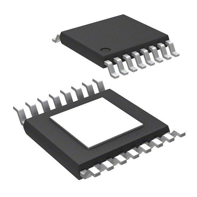
- Part No.:
- A6272KLPTR-T
- Manufacturer:
- Allegro MicroSystems
- Category:
- LED Drivers
- Package:
- 16-TSSOP (0.173", 4.40mm Width) Exposed Pad
- Datasheet:
-
 A6272KLPTR-T.pdf
- Description:
- IC LED DRVR LINEAR PWM 16ETSSOP
- Quantity:
- Payment:

- Shipping:

Inventory:3,943
Please send an inquiry. Send us your inquiry, and we will respond immediately.
Product details
Overview
A6272KLPTR-T from Allegro MicroSystems is an AEC-Q100-qualified automotive two-channel linear LED controller with internal PWM dimming, designed for stop/tail and DRL/position lighting. It regulates LED current via external N-channel MOSFETs with ±4% reference accuracy per channel, operates from 5.3 V to 40 V, and integrates drain short-to-ground/VIN, open-LED, thermal, and VIN derating protections.
For engineers reviewing the A6272KLPTR-T datasheet, A6272KLPTR-T pinout, A6272KLPTR-T application, or A6272KLPTR-T equivalent, this page delivers verified technical context, validated pin functions, confirmed fault-handling behavior in MODE = VBIAS vs. MODE = LOW, real-world dimming control options (internal resistor-set, external PWM, analog DR voltage), and precise thermal/VIN derating thresholds derived from VTHTH configuration.
Technical Context
The A6272KLPTR-T implements dual independent current regulation loops using internal 200 mV reference voltage applied to SENSE1/SENSE2 pins, enabling programmable peak LED current (ILED = 200 mA / RSENSE). Its PWM generator supports internal frequency setting (180–220 Hz via RFPWM) and analog duty cycle control (7–92% via DR pin voltage ratio to VBIAS).
Fault management is split by MODE pin state: when MODE = VBIAS, drain short-to-VIN and open-LED faults latch GATE1 low while maintaining 100% duty on the faulty channel; when MODE = LOW, only FF flag asserts low while both gates continue switching normally. Thermal derating begins at TJ = TJF – 21°C and full shutdown occurs at 170°C with 30°C hysteresis.
Key Specifications
| Parameter | Value and Actual Design Meaning |
|---|---|
| Supply Voltage Range | 5.3 V to 40 V - supports wide automotive battery range; operates down to 5.1 V during enable |
| Current Reference Accuracy | ±4% per channel - ensures consistent brightness across dual LED strings without calibration |
| PWM Dimming Frequency | 180–220 Hz (typ. 200 Hz) - set by resistor on PWM_IN; avoids audible noise and visible flicker |
| Reference Voltage (VREF) | 192–208 mV - stable 200 mV nominal; enables accurate current setting with external sense resistors |
| Thermal Shutdown Threshold | 170°C (typ.) - disables outputs to prevent damage; auto-restarts at 140°C |
| VIN Derating Threshold | Adjustable 16–36 V via VTHTH pin - reduces LED current above threshold to limit MOSFET power dissipation |
| Drain Short Detection | VIN – VDx < 0.8 V - detects MOSFET drain shorted to supply rail before catastrophic failure |
Pinout & Package
Package: 16-pin TSSOP (LP) with exposed thermal pad - Pb-free, matte-tin leadframe plating; optimized for automotive thermal cycling and solder joint reliability.
| Pin/Terminal | Circuit Role | Design Meaning |
|---|---|---|
| VIN | Power input | Primary supply input (5.3–40 V); powers internal bias and gate drivers |
| GATE1 / GATE2 | N-channel MOSFET gate drive | High-side gate drivers (6–9 V swing) controlling external FETs for each LED string |
| SENSE1 / SENSE2 | Current sense input | Inputs for external sense resistors; regulate LED current via 200 mV reference |
| D1 / D2 | Drain fault sensing | Monitor MOSFET drain voltage for short-to-GND, short-to-VIN, and open-LED conditions |
| DR | Analog dimming control | Accepts 0–3.6 V DC to set PWM duty cycle ratiometrically to VBIAS (7–92%) |
| PWM_IN | Dimming clock input | Accepts external PWM signal or resistor-set oscillator for internal dimming frequency |
| MODE | Fault response mode select | Configures fault behavior: VBIAS = latched protection; LOW = non-latching FF-only flag |
| FF | Fault flag output | Open-drain output pulled low during any active fault condition (short, open, thermal, VIN) |
| VTHTH | VIN derating & open-LED disable threshold | Sets VIN foldback start point (VINth(L) = 10 × VVTHTH + 0.7 V) and VOLED_dis = 5 × VVTHTH |
Key Features
| Feature | Design Value |
|---|---|
| Dual independent current regulation | Enables separate brightness control for stop/tail and DRL/position LED strings using two external MOSFETs |
| Three dimming control modes | Internal resistor-set PWM, external microcontroller PWM, or analog voltage on DR pin - supports flexible system architecture |
| Comprehensive fault detection | Simultaneous monitoring of drain short-to-GND, drain short-to-VIN, open-LED, overtemperature, and overvoltage - no external supervision needed |
| Programmable VIN derating | Reduces LED current above user-defined input voltage threshold to maintain safe MOSFET power dissipation |
| Thermal foldback with hysteresis | Gradually reduces LED current starting at TJ ≈ 149°C and shuts down completely at 170°C with 30°C recovery margin |
Applications
| Rear Combination Lamp (Stop/Tail) | Front Position/DRL Module |
|---|---|
Use Scenario: Dual-function rear lamp where one channel drives high-brightness stop LEDs and the other drives lower-brightness tail LEDs. IC Role / Device Role / Timing Role: Linear current controller managing two independent LED strings with full/partial duty cycle selection via FULL pin and DR voltage. Use Value: Enables single-chip implementation of ECE R7/SAE J585-compliant stop/tail functionality with ±4% current matching and fault-safe operation. |
Use Scenario: Daytime running light with position lamp fallback, requiring smooth dimming transitions and thermal stability under hood temperatures. IC Role / Device Role / Timing Role: Analog-controlled PWM dimmer using DR pin voltage to achieve precise luminance levels across ambient light conditions. Use Value: Delivers flicker-free, thermally compensated DRL output with automatic current reduction above 149°C junction temperature. |
| Multi-IC Parallel Lighting Array | Automotive Signal Lighting with Fault Reporting |
Use Scenario: High-power front/rear lighting module using multiple A6272KLPTR-T ICs in parallel to scale total LED current capacity. IC Role / Device Role / Timing Role: Synchronized current regulator where FF pins wire-OR to a central microcontroller for system-level fault aggregation. Use Value: Enables scalable, modular lighting designs with shared thermal derating and coordinated VIN foldback across all ICs. |
Use Scenario: Safety-critical exterior lighting requiring ISO 26262 ASIL-B-compatible fault reporting to vehicle body controller. IC Role / Device Role / Timing Role: Fault-aware LED driver providing real-time status via FF pin and configurable MODE pin behavior for diagnostic strategy. Use Value: Supports fail-operational design by distinguishing latched (MODE = VBIAS) vs. transient (MODE = LOW) faults for appropriate ECU response. |
Equivalent & Alternatives
The following parts are listed as comparable options for similar two-channel automotive LED controller applications.
| Alternative Part | Technical Difference | Application Difference | Selection Advice |
|---|---|---|---|
| A6270KLPTR-T | Lacks internal PWM generator; requires external PWM signal on PWM_IN; no DR pin for analog dimming control | Suitable for systems with existing MCU-based dimming timing; not usable for standalone analog dimming | Select when external microcontroller provides precise PWM timing and analog dimming is unnecessary |
| A6270-1KLPTR-T | Same base architecture as A6270 but adds integrated VBIAS LDO; no change to PWM or DR functionality | Reduces external BOM count by eliminating need for external VBIAS decoupling capacitor | Prefer for new designs seeking simplified layout and guaranteed VBIAS regulation stability |
Compared with A6272KLPTR-T, the A6270 variants omit internal PWM generation and DR-based analog dimming-making them less flexible for standalone lighting modules but more suitable for tightly controlled MCU-driven systems where timing precision and BOM minimization are prioritized over analog interface simplicity.
Availability
A6272KLPTR-T is available at Aetrix Electronics and suitable for automotive rear combination lamps, front DRL/position modules, multi-IC parallel lighting arrays, and safety-critical signal lighting requiring AEC-Q100 qualification and comprehensive fault reporting.
Supply support for A6272KLPTR-T includes scheduled delivery planning, volume procurement assistance, BOM continuity management, traceable sourcing, and lifecycle availability coordination for OEM customers, industrial embedded developers, connected-device designers, and electronics production programs.
Manufacturer
Allegro MicroSystems is a U.S.-based semiconductor company specializing in high-performance magnetic sensing, power ICs, and motor control solutions for automotive and industrial markets.
The A6272 product line was engineered specifically for AEC-Q100-compliant automotive LED lighting systems requiring dual-channel current regulation, robust fault handling, and flexible dimming interfaces - targeting stop/tail, DRL, and position lamp applications.
FAQ
What is the function of the DR pin on the A6272KLPTR-T?
The DR pin on the A6272KLPTR-T accepts an analog DC voltage (0–3.6 V) to set PWM dimming duty cycle ratiometrically to VBIAS, enabling precise luminance control without external clock signals. When DR is connected to VBIAS, the A6272KLPTR-T switches to external PWM mode and uses the PWM_IN pin for frequency and duty cycle. This dual-mode flexibility makes the A6272KLPTR-T adaptable to both standalone and microcontroller-coordinated lighting architectures.
How does the A6272KLPTR-T handle drain short-to-VIN faults?
The A6272KLPTR-T detects drain short-to-VIN when VIN – VDx falls below 0.8 V while both GATEs are asserted high. In MODE = VBIAS, it latches GATE1 low while maintaining 100% duty on the faulty channel and pulls FF low; in MODE = LOW, only FF asserts low while both gates continue normal switching. The A6272KLPTR-T's fault logic ensures safe operation without requiring external supervision, and recovery is automatic upon fault removal.
Can the A6272KLPTR-T be used in parallel configurations?
Yes, the A6272KLPTR-T supports parallel operation for higher-current LED arrays. All ICs synchronize via shared VIN, VTHTH, and MODE connections; FF pins are wire-OR'd to report aggregate system faults. Current matching remains within ±4% per channel, and thermal/VIN derating applies uniformly across parallel units. This capability allows scalable lighting designs without redesigning core driver architecture - a key advantage of the A6272KLPTR-T in modular automotive platforms.
What is the purpose of the VTHTH pin on the A6272KLPTR-T?
The VTHTH pin on the A6272KLPTR-T sets both the VIN derating threshold (VINth(L) = 10 × VVTHTH + 0.7 V) and the open-LED disable voltage (VOLED_dis = 5 × VVTHTH). By adjusting VTHTH voltage (1.6–3.6 V), designers configure the input voltage level at which LED current begins folding back to protect external MOSFETs, and simultaneously prevent false open-LED faults during cold cranking or low-battery conditions - a critical feature for robust automotive deployment of the A6272KLPTR-T.
Is the A6272KLPTR-T still in production?
No, the A6272KLPTR-T is a discontinued product as of September 30, 2024 and is no longer in production. Allegro MicroSystems advises against using the A6272KLPTR-T in new design applications. Samples are unavailable. For existing customer transition and new applications, Allegro recommends the A6270 and A6270-1 families as direct functional alternatives with updated feature sets and ongoing production support.
A6272KLPTR-T Specifications
- Product attributes
- Attribute value
- Manufacturer:
- Allegro MicroSystems
- Series:
- -
- Package/Case:
- 16-TSSOP (0.173", 4.40mm Width) Exposed Pad
- Packaging:
- Tape & Reel (TR)
- Product Status:
- Obsolete
- Type:
- Linear
- Topology:
- -
- Internal Switch(s):
- Yes
- Number of Outputs:
- 2
- Voltage - Supply (Min):
- 5.3V
- Voltage - Supply (Max):
- 40V
- Voltage - Output:
- -
- Current - Output / Channel:
- -
- Frequency:
- -
- Dimming:
- PWM
- Applications:
- Lighting
- Operating Temperature:
- 150°C (TJ)
- Grade:
- Automotive
- Qualification:
- AEC-Q100
- Mounting Type:
- Surface Mount
- Supplier Device Package:
- 16-eTSSOP-EP
A6272KLPTR-T FAQ
1.How can I place an order for A6272KLPTR-T through Aetrix?
Please submit a Request for Quotation (RFQ) for A6272KLPTR-T on Aetrix. Our sales agent will provide a competitive quotation and guide you through the order confirmation once you accept the terms.
2.Are the price and stock information for A6272KLPTR-T reliable?
The price and inventory of A6272KLPTR-T are updated periodically and may fluctuate due to market conditions. Stock and pricing data are typically refreshed every 24 hours. Quotation validity for A6272KLPTR-T is usually 5 days.
3.What payment methods are accepted for A6272KLPTR-T?
We accept Wire Transfer, PayPal, Credit Card, Western Union, MoneyGram, and Escrow for A6272KLPTR-T transactions.
Note: Certain payment methods may incur a processing fee.
4.How is shipping managed for A6272KLPTR-T?
A6272KLPTR-T orders can be shipped via leading logistics carriers, including DHL, UPS, FedEx, TNT, or Registered Mail.
Once your A6272KLPTR-T order is processed, you will receive an email with the shipment details and tracking number.
Note: Tracking information may take up to 24 hours to appear. Express delivery typically takes 3–5 business days.
5.How can I obtain technical support or documentation for A6272KLPTR-T?
For technical support, including A6272KLPTR-T datasheets, pinout diagrams, or application guidance, please contact our engineering support team. They can provide detailed documentation and assistance for your A6272KLPTR-T requirements.
6.How does Aetrix verify that A6272KLPTR-T is sourced from the original manufacturer or authorized distributors?
All A6272KLPTR-T products on Aetrix are procured from qualified distributors and authorized channels. Our dedicated quality assurance team conducts strict verification, including traceability checks and, if necessary, third-party testing. This ensures that A6272KLPTR-T meets industry standards.
7.What is the process for return or replacement of A6272KLPTR-T?
All A6272KLPTR-T units undergo pre-shipment inspection (PSI). If there is an issue with A6272KLPTR-T, returns or replacements are accepted under the following conditions:
1.Quantity discrepancies, incorrect items, or visible external defects (such as breakage or corrosion), acknowledged by Aetrix.
2.The issue is reported within 90 days of delivery.
3.The A6272KLPTR-T part is unused and in its original packaging.
Return procedure for A6272KLPTR-T:
1.Submit a request within 90 days.
2.Obtain a Return Material Authorization (RMA) from Aetrix.
A6272KLPTR-T Tags

-
BCR402RE6327HTSA1
Infineon Technologies

-
BCR430UXTSA2
Infineon Technologies

-
BCR420UE6433HTMA1
Infineon Technologies
-
BCR420UE6327HTSA1
Infineon Technologies
-
BCR421UE6327HTSA1
Infineon Technologies

-
LYT1604D-TL
Power Integrations

-
HV9910CLG-G
Microchip Technology

-
CL2N8-G
Microchip Technology

-
BCR420UW6-7
Diodes Incorporated
-
BCR421UW6-7
Diodes Incorporated

-
BCR420UFD-7
Diodes Incorporated
-
BCR421UFD-7
Diodes Incorporated
Tech Hub

A practical engineering and sourcing framework covering lifecycle verification, lifetime-buy calculations, replacement qualification, supplier checks and counterfeit-risk controls.

TTL and CMOS logic families differ in thresholds, loading, output drive, power and timing. This engineering guide compares 74HC and 74HCT, calculates noise margins and checks 3.3 V/5 V compatibility.

A practical engineering guide to 3.3V and 5V logic compatibility, input thresholds, resistor dividers, translator ICs, MOSFET level shifting, I2C pull-ups, timing limits and power-sequencing risks.

The 74HC595 uses push-pull logic outputs, while the TPIC6B595 uses 50 V open-drain DMOS sinks for higher-power loads. This guide compares timing, current limits, 3.3 V interfacing, load wiring, thermal…

The 74HC595 converts serial data into eight stable parallel outputs. This guide covers pin functions, shift and storage timing, OE and MR behavior, drive-current limits, cascading, voltage compatibilit…

A technical comparison of level-sensitive latches and edge-triggered flip-flops, covering timing windows, setup and hold limits, master–slave operation, time borrowing, race-through, HDL inference and…

A D latch stores one bit while Enable controls when data can pass. This reference covers gate-level operation, truth tables, transparency, setup and hold timing, LE versus OE, common ICs and practical …

An SR latch stores one bit through cross-coupled feedback. This engineering reference covers NOR and NAND implementations, truth tables, forbidden-state recovery, gated operation, switch debouncing, fa…

Latch circuits retain one bit through feedback. This technical reference covers SR and D latches, truth tables, transparency, timing limits, latch-versus-flip-flop behavior, applications and common log…

An engineering guide to LED driver operation, constant-current and constant-voltage outputs, linear and switching topologies, dimming, IC selection, calculations, replacement compatibility, and fault c…


