
 My Inquiry
 My Account


Allegro MicroSystems A6275ELWTR
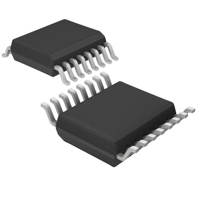
- Part No.:
- A6275ELWTR
- Manufacturer:
- Allegro MicroSystems
- Category:
- LED Drivers
- Package:
- 16-SOIC (0.295", 7.50mm Width)
- Datasheet:
-
 A6275ELWTR.pdf
- Description:
- IC LED DRVR LINEAR 75.5MA 16SOIC
- Quantity:
- Payment:

- Shipping:

Inventory:1,915
Please send an inquiry. Send us your inquiry, and we will respond immediately.
Product details
Overview
A6275ELWTR from Allegro MicroSystems is an 8-bit serial-input constant-current latched LED driver with eight NPN sink outputs, 90 mA max per channel, undervoltage lockout (UVLO), and CMOS-compatible 5 V logic interface - designed for multiplexed LED displays requiring precise current regulation and microprocessor-controlled blanking.
For engineers reviewing the A6275ELWTR datasheet, A6275ELWTR pinout, A6275ELWTR application, or A6275ELWTR equivalent, this page delivers verified technical context, real-world timing constraints (10 MHz max clock), thermal derating guidance, REXT-based current setting, and cascade-capable serial data output - all critical for display driver selection and layout validation.
Technical Context
The A6275ELWTR integrates a 8-bit CMOS shift register, parallel latches, and eight bipolar NPN constant-current sink drivers in a single BiCMOS die. It operates with 4.5–5.5 V logic supply and supports serial data rates up to 10 MHz under cascade conditions, with propagation delays ≤1000 ns across CLOCK/LATCH/ENABLE-to-OUT paths.
Current regulation is set externally via REXT (e.g., 250 Ω yields 75.5 mA typ at VCE = 0.7 V), and output enable (active-low) provides inter-digit blanking. Undervoltage lockout triggers at 3.4–4.0 V to prevent erratic operation during power ramp-up.
Key Specifications
| Parameter | Value and Actual Design Meaning |
|---|---|
| Output Type | Eight NPN constant-current sink drivers, each rated 90 mA continuous at 85°C |
| Logic Supply | 4.5–5.5 V - compatible with standard 5 V microcontroller I/O without level shifting |
| Max Clock Frequency | 10 MHz - enables fast refresh in high-resolution LED matrices with minimal serial overhead |
| UVLO Threshold | 3.4–4.0 V - ensures stable initialization and prevents partial latch activation during brownout |
| Output Current Matching | ±1.5% typical (REXT = 250 Ω) - maintains uniform LED brightness across all 8 channels |
| Thermal Resistance | RθJA = 48 °C/W (SOICW package) - requires PCB copper area planning for >50 mA sustained loads |
| Serial Data Output | CMOS-compatible - allows daisy-chaining multiple A6275ELWTR devices without external buffers |
Pinout & Package
Package: 16-pin SOICW (wide-body surface-mount), lead-free with 100% matte tin plating, JEDEC MS-013 AA compliant.
| Pin/Terminal | Circuit Role | Design Meaning |
|---|---|---|
| 1, 2, 3, 4, 8, 9, 10, 11 | GND | Common logic and power ground reference - must be low-impedance to avoid latch mis-triggering from switching noise |
| 2 | SERIAL DATA IN | CMOS input accepting 0–5 V serial data; data loaded on rising edge of CLOCK |
| 3 | CLOCK | CMOS input; rising-edge triggered shift register clock (max 10 MHz) |
| 4 | LATCH ENABLE | CMOS input; high level transfers shift register contents to output latches (transparent mode if held high) |
| 5–12 | OUT0–OUT7 | NPN open-collector sink outputs; each drives one LED cathode with user-set current via REXT |
| 13 | OUTPUT ENABLE | Active-low CMOS input; disables all outputs simultaneously for inter-digit blanking |
| 14 | SERIAL DATA OUT | CMOS output; forwards shifted-out bit to next device in cascade chain |
| 15 | REXT | Analog input; connects external resistor to set identical current for all 8 outputs (e.g., 250 Ω → 75.5 mA) |
| 16 | VDD | 5 V logic supply input; powers internal CMOS logic, latches, and UVLO circuitry |
Key Features
| Feature | Design Value |
|---|---|
| Constant-current sink outputs | Each output delivers tightly matched current (±1.5% typ) independent of VCE variation - eliminates need for per-LED resistors |
| Undervoltage lockout (UVLO) | Prevents erroneous data latching or partial output activation during power-up/down sequences below 3.4 V |
| High-speed serial interface | Supports 10 MHz clock with 300–1000 ns propagation delay - enables sub-100 µs full 8-bit update for flicker-free display refresh |
| Cascade-capable serial output | CMOS-level SERIAL DATA OUT allows direct connection to next A6275ELWTR's SERIAL DATA IN - no glue logic required for multi-device chains |
| Inter-digit blanking control | Single active-low OUTPUT ENABLE pin disables all 8 outputs simultaneously - essential for time-multiplexed LED matrix scanning |
Applications
| LED Matrix Displays | Industrial Panel Indicators |
|---|---|
|
Use Scenario: Driving 8×N segmented LED matrices in point-of-sale terminals and instrumentation panels using time-multiplexed scanning. IC Role / Device Role / Timing Role: Constant-current sink driver providing synchronized digit blanking and per-segment current regulation via REXT. Use Value: Eliminates 64 individual current-limiting resistors while maintaining ±1.5% brightness uniformity across all segments at 10 MHz update rate. |
Use Scenario: Controlling status LEDs on programmable logic controllers (PLCs) with microcontroller-based serial command streams. IC Role / Device Role / Timing Role: Serial-to-parallel latched driver translating SPI-like commands into stable LED on/off states with glitch-free transitions. Use Value: Reduces GPIO count by 8× and removes software timing dependency for LED state updates - improves firmware determinism. |
| Automotive Dashboard Modules | Appliance Control Panels |
|
Use Scenario: Illuminating segmented warning indicators (e.g., oil pressure, brake, battery) in automotive instrument clusters operating from 12 V supply rails. IC Role / Device Role / Timing Role: High-side LED driver interface (with external PNP/MOSFET) enabling common-anode LED configurations and UVLO-protected startup. Use Value: Ensures reliable indicator activation only after system voltage stabilizes above 3.4 V - prevents false warnings during ignition crank. |
Use Scenario: Managing backlight and function LEDs on microwave oven or washing machine control panels exposed to temperature cycling (-20 to +85°C). IC Role / Device Role / Timing Role: Temperature-stable current sink delivering consistent LED intensity across ambient range without recalibration. Use Value: Maintains 90 mA output capability at 85°C ambient with SOICW package - avoids brightness drift in thermally stressed enclosures. |
Equivalent & Alternatives
The following parts are listed as comparable options for similar constant-current LED driver applications.
| Alternative Part | Technical Difference | Application Difference | Selection Advice |
|---|---|---|---|
| A6279 | Successor device with enhanced ESD rating (Class 3), improved thermal performance (RθJA = 42 °C/W), and extended current range (up to 100 mA) | Pin-compatible replacement with same SOICW-16 footprint and identical functional block diagram; supports legacy A6275 designs with no layout change | Select A6279 for new designs requiring longer product lifecycle support and higher reliability in industrial environments. |
| TB62705CP | Pin-compatible 8-bit LED driver from Toshiba; similar 90 mA rating but lacks UVLO and has lower max clock (5 MHz) | Requires external UVLO circuitry and limits display refresh rate; not suitable for high-speed multiplexing or brownout-prone systems | Consider TB62705CP only if sourcing A6275ELWTR is unavailable and UVLO/timing requirements are relaxed. |
Compared with A6275ELWTR, the A6279 offers drop-in compatibility with better thermal margin and ESD robustness, while TB62705CP requires design compromises in reliability and speed - making A6279 the preferred upgrade path for continuity-critical applications.
Availability
A6275ELWTR is available at Aetrix Electronics and suitable for LED matrix displays, industrial panel indicators, automotive dashboard modules, appliance control panels, and time-multiplexed signage requiring stable component supply despite its Last Time Buy status.
Supply support for A6275ELWTR includes scheduled delivery planning, volume procurement assistance, BOM continuity management, traceable sourcing, and lifecycle availability coordination for OEM customers, industrial embedded developers, connected-device designers, and electronics production programs.
Manufacturer
Allegro MicroSystems is a U.S.-based designer and manufacturer of high-performance magnetic sensors, motor drivers, and power ICs, founded in 1989 and headquartered in Worcester, Massachusetts.
The A6275 product line was developed specifically for cost-sensitive, high-reliability LED display systems requiring integrated constant-current sinking, serial control, and thermal robustness in industrial and automotive environments.
FAQ
What is the maximum continuous output current per channel for the A6275ELWTR?
The A6275ELWTR supports up to 90 mA continuous current per output channel (OUT0–OUT7) when operated within its specified ambient temperature range (–40 to +85°C) and with proper PCB thermal design. This rating assumes VCE ≤ 0.9 V and is validated for the SOICW package at 85°C ambient with RθJA = 48 °C/W. Derating applies above 85°C or with higher VCE.
Does the A6275ELWTR include undervoltage lockout, and what is its threshold?
Yes, the A6275ELWTR includes built-in undervoltage lockout (UVLO) that disables internal logic and outputs when VDD falls below 3.4 V (typical) and re-enables operation once VDD rises above 4.0 V (typical). This feature prevents erratic behavior during power-up or brownout conditions and is confirmed in the Electrical Characteristics table on page 4 of the official Allegro datasheet for A6275ELWTR.
How is output current set on the A6275ELWTR, and what resistor value yields ~75 mA?
Output current on the A6275ELWTR is set by a single external resistor (REXT) connected between pin 15 and ground. At VCE = 0.7 V, a 250 Ω resistor yields 75.5 mA typical output current per channel, as specified in the Electrical Characteristics table. The relationship is inverse-linear: lower REXT increases current, higher REXT decreases it - with 470 Ω yielding ~40 mA typical.
Is the A6275ELWTR pin-compatible with the A6279, and can it be used as a drop-in replacement?
Yes, the A6275ELWTR is pin-compatible with the A6279 and functions as a direct drop-in replacement in existing designs. Both share identical SOICW-16 pinout, electrical interface, and functional architecture. The A6279 adds Class 3 ESD protection and improved thermal resistance (42 °C/W vs. 48 °C/W), but requires no PCB or firmware changes - making it the recommended successor for new production runs of A6275ELWTR-based systems.
What is the maximum allowable clock frequency for the A6275ELWTR in cascade mode?
The A6275ELWTR supports a maximum clock frequency of 10 MHz in cascade mode, as specified in the Recommended Operating Conditions table. This limit accounts for cumulative propagation delay and signal integrity across chained devices. At 25°C and VDD = 5 V, timing parameters (e.g., tsu(D) = 50 ns, tw(CK) = 50 ns) confirm reliable operation up to this rate - exceeding it risks setup/hold violations and data corruption in the shift register.
A6275ELWTR Specifications
- Product attributes
- Attribute value
- Manufacturer:
- Allegro MicroSystems
- Series:
- -
- Package/Case:
- 16-SOIC (0.295", 7.50mm Width)
- Packaging:
- Tape & Reel (TR)
- Product Status:
- Obsolete
- Type:
- Linear
- Topology:
- Shift Register
- Internal Switch(s):
- Yes
- Number of Outputs:
- 8
- Voltage - Supply (Min):
- 4.5V
- Voltage - Supply (Max):
- 5.5V
- Voltage - Output:
- 4V
- Current - Output / Channel:
- 75.5mA
- Frequency:
- 20MHz
- Dimming:
- -
- Applications:
- -
- Operating Temperature:
- -40°C ~ 85°C (TA)
- Grade:
- -
- Qualification:
- -
- Mounting Type:
- Surface Mount
- Supplier Device Package:
- 16-SOIC
A6275ELWTR FAQ
1.How can I place an order for A6275ELWTR through Aetrix?
Please submit a Request for Quotation (RFQ) for A6275ELWTR on Aetrix. Our sales agent will provide a competitive quotation and guide you through the order confirmation once you accept the terms.
2.Are the price and stock information for A6275ELWTR reliable?
The price and inventory of A6275ELWTR are updated periodically and may fluctuate due to market conditions. Stock and pricing data are typically refreshed every 24 hours. Quotation validity for A6275ELWTR is usually 5 days.
3.What payment methods are accepted for A6275ELWTR?
We accept Wire Transfer, PayPal, Credit Card, Western Union, MoneyGram, and Escrow for A6275ELWTR transactions.
Note: Certain payment methods may incur a processing fee.
4.How is shipping managed for A6275ELWTR?
A6275ELWTR orders can be shipped via leading logistics carriers, including DHL, UPS, FedEx, TNT, or Registered Mail.
Once your A6275ELWTR order is processed, you will receive an email with the shipment details and tracking number.
Note: Tracking information may take up to 24 hours to appear. Express delivery typically takes 3–5 business days.
5.How can I obtain technical support or documentation for A6275ELWTR?
For technical support, including A6275ELWTR datasheets, pinout diagrams, or application guidance, please contact our engineering support team. They can provide detailed documentation and assistance for your A6275ELWTR requirements.
6.How does Aetrix verify that A6275ELWTR is sourced from the original manufacturer or authorized distributors?
All A6275ELWTR products on Aetrix are procured from qualified distributors and authorized channels. Our dedicated quality assurance team conducts strict verification, including traceability checks and, if necessary, third-party testing. This ensures that A6275ELWTR meets industry standards.
7.What is the process for return or replacement of A6275ELWTR?
All A6275ELWTR units undergo pre-shipment inspection (PSI). If there is an issue with A6275ELWTR, returns or replacements are accepted under the following conditions:
1.Quantity discrepancies, incorrect items, or visible external defects (such as breakage or corrosion), acknowledged by Aetrix.
2.The issue is reported within 90 days of delivery.
3.The A6275ELWTR part is unused and in its original packaging.
Return procedure for A6275ELWTR:
1.Submit a request within 90 days.
2.Obtain a Return Material Authorization (RMA) from Aetrix.
A6275ELWTR Tags

-
BCR402RE6327HTSA1
Infineon Technologies

-
BCR430UXTSA2
Infineon Technologies

-
BCR420UE6433HTMA1
Infineon Technologies
-
BCR420UE6327HTSA1
Infineon Technologies
-
BCR421UE6327HTSA1
Infineon Technologies

-
LYT1604D-TL
Power Integrations

-
HV9910CLG-G
Microchip Technology

-
CL2N8-G
Microchip Technology

-
BCR420UW6-7
Diodes Incorporated
-
BCR421UW6-7
Diodes Incorporated

-
BCR420UFD-7
Diodes Incorporated
-
BCR421UFD-7
Diodes Incorporated
Tech Hub

A practical engineering and sourcing framework covering lifecycle verification, lifetime-buy calculations, replacement qualification, supplier checks and counterfeit-risk controls.

TTL and CMOS logic families differ in thresholds, loading, output drive, power and timing. This engineering guide compares 74HC and 74HCT, calculates noise margins and checks 3.3 V/5 V compatibility.

A practical engineering guide to 3.3V and 5V logic compatibility, input thresholds, resistor dividers, translator ICs, MOSFET level shifting, I2C pull-ups, timing limits and power-sequencing risks.

The 74HC595 uses push-pull logic outputs, while the TPIC6B595 uses 50 V open-drain DMOS sinks for higher-power loads. This guide compares timing, current limits, 3.3 V interfacing, load wiring, thermal…

The 74HC595 converts serial data into eight stable parallel outputs. This guide covers pin functions, shift and storage timing, OE and MR behavior, drive-current limits, cascading, voltage compatibilit…

A technical comparison of level-sensitive latches and edge-triggered flip-flops, covering timing windows, setup and hold limits, master–slave operation, time borrowing, race-through, HDL inference and…

A D latch stores one bit while Enable controls when data can pass. This reference covers gate-level operation, truth tables, transparency, setup and hold timing, LE versus OE, common ICs and practical …

An SR latch stores one bit through cross-coupled feedback. This engineering reference covers NOR and NAND implementations, truth tables, forbidden-state recovery, gated operation, switch debouncing, fa…

Latch circuits retain one bit through feedback. This technical reference covers SR and D latches, truth tables, transparency, timing limits, latch-versus-flip-flop behavior, applications and common log…

An engineering guide to LED driver operation, constant-current and constant-voltage outputs, linear and switching topologies, dimming, IC selection, calculations, replacement compatibility, and fault c…


