
 My Inquiry
 My Account


Allegro MicroSystems A6275SLWTR-T
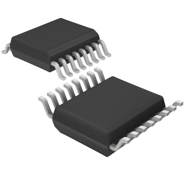
- Part No.:
- A6275SLWTR-T
- Manufacturer:
- Allegro MicroSystems
- Category:
- LED Drivers
- Package:
- 16-SOIC (0.295", 7.50mm Width)
- Datasheet:
-
 A6275SLWTR-T.pdf
- Description:
- IC LED DRVR LINEAR 75.5MA 16SOIC
- Quantity:
- Payment:

- Shipping:

Inventory:3,326
Please send an inquiry. Send us your inquiry, and we will respond immediately.
Product details
Overview
A6275SLWTR-T from Allegro MicroSystems is an 8-bit serial-input constant-current latched LED driver with eight NPN sink outputs, 90 mA max per channel, undervoltage lockout, and CMOS shift register/latch logic-designed for multiplexed LED displays in industrial signage and instrumentation panels.
For engineers reviewing the A6275SLWTR-T datasheet, A6275SLWTR-T pinout, A6275SLWTR-T application, or A6275SLWTR-T equivalent, key selection factors include its SOICW-16 package, –20°C to +85°C ambient rating, external resistor–set current (40 mA typical at REXT = 470 Ω), ENABLE-controlled blanking, and cascade-capable serial data output.
Technical Context
The A6275SLWTR-T integrates a BiCMOS 8-bit serial-to-parallel shift register followed by transparent latches and eight matched NPN constant-current sink drivers. Its logic operates from a 4.5–5.5 V supply, supporting up to 10 MHz clock frequency and 20 MHz serial data input rates under 5 V conditions.
Undervoltage lockout activates below 3.4–4.0 V VDD, preventing erratic operation during power ramp-up. Output current is set externally via REXT (e.g., 40 mA at 470 Ω, 75.5 mA typical at 250 Ω), with ±6.0% matching across outputs and <5.0 μA leakage at 15 V.
Key Specifications
| Parameter | Value and Actual Design Meaning |
|---|---|
| Output Type | NPN constant-current sink drivers (8-channel) |
| Max Output Current | 90 mA per channel, continuous at 85°C with 0.9 V drop |
| Supply Voltage | 4.5–5.5 V - supports standard 5 V microcontroller interfaces |
| UVLO Threshold | 3.4–4.0 V - ensures reliable startup and brownout immunity |
| Serial Clock Frequency | Up to 10 MHz - enables fast display refresh in high-resolution LED matrices |
| Propagation Delay | 300–1000 ns (CLOCK/LATCH/ENABLE to OUT) - supports tight timing margins |
| Operating Temp Range | –20°C to +85°C - qualified for commercial/industrial signage environments |
Pinout & Package
Package: 16-pin SOICW (wide-body surface-mount), RoHS-compliant, 100% matte tin leadframe plating, JEDEC MS-013 AA compliant.
| Pin/Terminal | Circuit Role | Design Meaning |
|---|---|---|
| 1 GND | Logic ground reference | Common return for shift register, latches, and control inputs |
| 2 SERIAL DATA IN | Shift register serial input | Accepts 5 V CMOS-level data on rising clock edge |
| 3 CLOCK | Shift register clock input | Rising-edge triggered; supports up to 10 MHz operation |
| 4 LATCH ENABLE | Data strobe control | High level transfers shift register contents to output latches |
| 5–12 OUT0–OUT7 | Constant-current sink outputs | Each sinks up to 90 mA; current set by single REXT on Pin 15 |
| 13 OUTPUT ENABLE | Global output blanking | Active-low: drives all outputs OFF when high (blanking mode) |
| 14 SERIAL DATA OUT | Cascade serial output | CMOS-level output for daisy-chaining multiple A6275 devices |
| 15 REXT | Current-setting resistor node | Connects external resistor to set identical current for all 8 outputs |
| 16 VDD | Logic supply input | 4.5–5.5 V CMOS supply; powers internal logic and UVLO circuitry |
Key Features
| Feature | Design Value |
|---|---|
| 8-bit serial-to-parallel conversion | Reduces MCU GPIO count to 3 pins (DATA, CLOCK, LATCH) for full 8-output control |
| External current programming | Single REXT sets precise, temperature-stable sink current across all channels |
| Inter-digit blanking support | Active-high OUTPUT ENABLE disables all outputs simultaneously for multiplexed display timing |
| Undervoltage lockout (UVLO) | Prevents partial logic operation during power-up/down, eliminating display glitches |
| Cascade-capable serial output | Enables expansion beyond 8 outputs without additional MCU interface lines |
Applications
| LED Matrix Signage | Industrial Panel Meters |
|---|---|
Use Scenario: Outdoor alphanumeric LED signs requiring high brightness, thermal stability, and long-term reliability under variable ambient temperatures. IC Role / Device Role / Timing Role: Constant-current sink driver for 8-segment digits or pixel rows; handles inter-digit blanking and serial data chaining across modules. Use Value: Delivers stable 40–90 mA per segment across –20°C to +85°C, minimizing brightness drift and enabling uniform luminance without per-channel calibration. | Use Scenario: Front-panel LED indicators in programmable logic controllers (PLCs) and HMI devices where EMI resilience and low logic power are critical. IC Role / Device Role / Timing Role: Interface between 5 V microcontroller and discrete LED indicators; provides latch-based persistence and noise-immune serial control. Use Value: Low 0.8–1.4 mA standby current (IDD(OFF)) extends system power budget; CMOS inputs tolerate >2.5 V common-mode noise on shared PCB ground planes. |
| Test Equipment Displays | Appliance Control Panels |
Use Scenario: Benchtop multimeters and oscilloscopes using multiplexed 7-segment LED displays with rapid update rates and zero flicker. IC Role / Device Role / Timing Role: Serial-input latched driver synchronized to system clock; enables precise digit-by-digit enable timing via OUTPUT ENABLE. Use Value: 300–1000 ns propagation delay ensures sub-microsecond timing alignment across digits; 10 MHz clock support allows >1 kHz full-display refresh. | Use Scenario: Consumer appliance status displays (microwaves, washing machines) requiring cost-effective, robust LED drive with minimal BOM count. IC Role / Device Role / Timing Role: Single-chip solution replacing discrete transistors/resistors for 8 indicator LEDs; driven directly from MCU GPIOs. Use Value: Eliminates 16 passive components (8 resistors + 8 transistors); SOICW-16 footprint simplifies layout and reduces assembly cost versus DIP alternatives. |
Equivalent & Alternatives
The following parts are listed as comparable options for similar constant-current LED driver applications.
| Alternative Part | Technical Difference | Application Difference | Selection Advice |
|---|---|---|---|
| A6279 | Successor device with enhanced open-LED detection, dot correction, and improved thermal performance; same 16-pin SOICW package | Supports diagnostic feedback and per-channel current tuning-required for high-reliability displays with fault reporting | Select A6279 for new designs needing diagnostics; A6275SLWTR-T remains viable for legacy replacement where those features are unused |
| TB62705CP | Pin-compatible 8-bit constant-current sink driver (Toshiba); similar 90 mA rating but no UVLO or serial data out | Lacks cascade capability and undervoltage protection-suitable only in stable 5 V systems without daisy-chain requirements | Use TB62705CP only if serial output and UVLO are unnecessary and existing PCB layout must be retained |
Compared with A6275SLWTR-T, the A6279 adds open-LED detection and dot correction while maintaining pinout and basic functionality-making it a functional upgrade for new designs. The TB62705CP offers mechanical compatibility but omits key reliability features like UVLO and cascading, limiting its use to simpler, non-diagnostic applications.
Availability
A6275SLWTR-T is available at Aetrix Electronics and suitable for LED matrix signage, industrial panel meters, test equipment displays, and appliance control panels requiring stable component supply despite its Last Time Buy status.
Supply support for A6275SLWTR-T includes scheduled delivery planning, volume procurement assistance, BOM continuity management, traceable sourcing, and lifecycle availability coordination for OEM customers, industrial embedded developers, connected-device designers, and electronics production programs.
Manufacturer
Allegro MicroSystems is a U.S.-based designer and manufacturer of high-performance magnetic sensors, motor drivers, and power ICs, headquartered in Worcester, Massachusetts.
The A6275 product line was developed specifically for cost-sensitive, high-reliability LED display systems requiring integrated constant-current sinking, serial control, and thermal robustness in commercial and light-industrial environments.
FAQ
What is the operating temperature range for the A6275SLWTR-T?
The A6275SLWTR-T is rated for an ambient operating temperature range of –20°C to +85°C. This specification applies specifically to the "S" grade variant denoted by the "S" in the part number, distinguishing it from the "E" grade (–40°C to +85°C) used in A6275EA-T and A6275ELWTR-T. Thermal derating curves in the datasheet confirm continuous 90 mA operation across this full range when mounted on a 4-layer PCB with RθJA = 48°C/W.
How is output current set on the A6275SLWTR-T?
Output current on the A6275SLWTR-T is set by a single external resistor (REXT) connected between Pin 15 (REXT) and ground. For example, a 470 Ω resistor yields a typical output current of 40.0 mA per channel at VCE = 0.7 V, while a 250 Ω resistor yields 75.5 mA. The relationship is inverse and linear: lower resistance increases current. The A6275SLWTR-T does not include internal current DACs or digital programming-current is purely analog and resistor-determined.
Is the A6275SLWTR-T pin-compatible with other devices in the A6275 family?
Yes, the A6275SLWTR-T shares identical pinout and electrical behavior with the A6275EA-T (DIP-16) and A6275ELWTR-T (SOICW-16). All three variants use the same 16-pin SOICW or DIP footprint, identical terminal functions, and identical logic thresholds, timing, and current-setting methodology. The only differences are package type and ambient temperature grade-making them direct drop-in replacements at the board level when mechanical constraints allow.
Does the A6275SLWTR-T support daisy-chaining with other LED drivers?
Yes, the A6275SLWTR-T supports daisy-chaining via its CMOS SERIAL DATA OUT (Pin 14), which outputs the shifted-out bit from the internal 8-bit shift register. This allows multiple A6275SLWTR-T devices to be connected in series: the DATA OUT of one feeds the DATA IN of the next, enabling expansion beyond 8 outputs using only three MCU control lines (CLOCK, LATCH ENABLE, and first-stage DATA IN). No additional glue logic or level-shifting is required.
What does "Last Time Buy" mean for the A6275SLWTR-T?
"Last Time Buy" indicates that the A6275SLWTR-T is obsolete and no longer in active production. Allegro issued formal notice ending manufacturing, with the final order deadline set for April 30, 2011. Aetrix Electronics maintains limited legacy stock for existing customer applications only; the A6275SLWTR-T is not recommended for new designs. For new projects, Allegro recommends the A6279 as a direct functional successor with enhanced diagnostics and continued production support.
A6275SLWTR-T Specifications
- Product attributes
- Attribute value
- Manufacturer:
- Allegro MicroSystems
- Series:
- -
- Package/Case:
- 16-SOIC (0.295", 7.50mm Width)
- Packaging:
- Tape & Reel (TR)
- Product Status:
- Obsolete
- Type:
- Linear
- Topology:
- Shift Register
- Internal Switch(s):
- Yes
- Number of Outputs:
- 8
- Voltage - Supply (Min):
- 4.5V
- Voltage - Supply (Max):
- 5.5V
- Voltage - Output:
- 4V
- Current - Output / Channel:
- 75.5mA
- Frequency:
- 20MHz
- Dimming:
- -
- Applications:
- -
- Operating Temperature:
- -20°C ~ 85°C (TA)
- Grade:
- -
- Qualification:
- -
- Mounting Type:
- Surface Mount
- Supplier Device Package:
- 16-SOIC
A6275SLWTR-T FAQ
1.How can I place an order for A6275SLWTR-T through Aetrix?
Please submit a Request for Quotation (RFQ) for A6275SLWTR-T on Aetrix. Our sales agent will provide a competitive quotation and guide you through the order confirmation once you accept the terms.
2.Are the price and stock information for A6275SLWTR-T reliable?
The price and inventory of A6275SLWTR-T are updated periodically and may fluctuate due to market conditions. Stock and pricing data are typically refreshed every 24 hours. Quotation validity for A6275SLWTR-T is usually 5 days.
3.What payment methods are accepted for A6275SLWTR-T?
We accept Wire Transfer, PayPal, Credit Card, Western Union, MoneyGram, and Escrow for A6275SLWTR-T transactions.
Note: Certain payment methods may incur a processing fee.
4.How is shipping managed for A6275SLWTR-T?
A6275SLWTR-T orders can be shipped via leading logistics carriers, including DHL, UPS, FedEx, TNT, or Registered Mail.
Once your A6275SLWTR-T order is processed, you will receive an email with the shipment details and tracking number.
Note: Tracking information may take up to 24 hours to appear. Express delivery typically takes 3–5 business days.
5.How can I obtain technical support or documentation for A6275SLWTR-T?
For technical support, including A6275SLWTR-T datasheets, pinout diagrams, or application guidance, please contact our engineering support team. They can provide detailed documentation and assistance for your A6275SLWTR-T requirements.
6.How does Aetrix verify that A6275SLWTR-T is sourced from the original manufacturer or authorized distributors?
All A6275SLWTR-T products on Aetrix are procured from qualified distributors and authorized channels. Our dedicated quality assurance team conducts strict verification, including traceability checks and, if necessary, third-party testing. This ensures that A6275SLWTR-T meets industry standards.
7.What is the process for return or replacement of A6275SLWTR-T?
All A6275SLWTR-T units undergo pre-shipment inspection (PSI). If there is an issue with A6275SLWTR-T, returns or replacements are accepted under the following conditions:
1.Quantity discrepancies, incorrect items, or visible external defects (such as breakage or corrosion), acknowledged by Aetrix.
2.The issue is reported within 90 days of delivery.
3.The A6275SLWTR-T part is unused and in its original packaging.
Return procedure for A6275SLWTR-T:
1.Submit a request within 90 days.
2.Obtain a Return Material Authorization (RMA) from Aetrix.
A6275SLWTR-T Tags

-
BCR402RE6327HTSA1
Infineon Technologies

-
BCR430UXTSA2
Infineon Technologies

-
BCR420UE6433HTMA1
Infineon Technologies
-
BCR420UE6327HTSA1
Infineon Technologies
-
BCR421UE6327HTSA1
Infineon Technologies

-
LYT1604D-TL
Power Integrations

-
HV9910CLG-G
Microchip Technology

-
CL2N8-G
Microchip Technology

-
BCR420UW6-7
Diodes Incorporated
-
BCR421UW6-7
Diodes Incorporated

-
BCR420UFD-7
Diodes Incorporated
-
BCR421UFD-7
Diodes Incorporated
Tech Hub

A practical engineering and sourcing framework covering lifecycle verification, lifetime-buy calculations, replacement qualification, supplier checks and counterfeit-risk controls.

TTL and CMOS logic families differ in thresholds, loading, output drive, power and timing. This engineering guide compares 74HC and 74HCT, calculates noise margins and checks 3.3 V/5 V compatibility.

A practical engineering guide to 3.3V and 5V logic compatibility, input thresholds, resistor dividers, translator ICs, MOSFET level shifting, I2C pull-ups, timing limits and power-sequencing risks.

The 74HC595 uses push-pull logic outputs, while the TPIC6B595 uses 50 V open-drain DMOS sinks for higher-power loads. This guide compares timing, current limits, 3.3 V interfacing, load wiring, thermal…

The 74HC595 converts serial data into eight stable parallel outputs. This guide covers pin functions, shift and storage timing, OE and MR behavior, drive-current limits, cascading, voltage compatibilit…

A technical comparison of level-sensitive latches and edge-triggered flip-flops, covering timing windows, setup and hold limits, master–slave operation, time borrowing, race-through, HDL inference and…

A D latch stores one bit while Enable controls when data can pass. This reference covers gate-level operation, truth tables, transparency, setup and hold timing, LE versus OE, common ICs and practical …

An SR latch stores one bit through cross-coupled feedback. This engineering reference covers NOR and NAND implementations, truth tables, forbidden-state recovery, gated operation, switch debouncing, fa…

Latch circuits retain one bit through feedback. This technical reference covers SR and D latches, truth tables, transparency, timing limits, latch-versus-flip-flop behavior, applications and common log…

An engineering guide to LED driver operation, constant-current and constant-voltage outputs, linear and switching topologies, dimming, IC selection, calculations, replacement compatibility, and fault c…


