
 My Inquiry
 My Account


Allegro MicroSystems A6276SLW
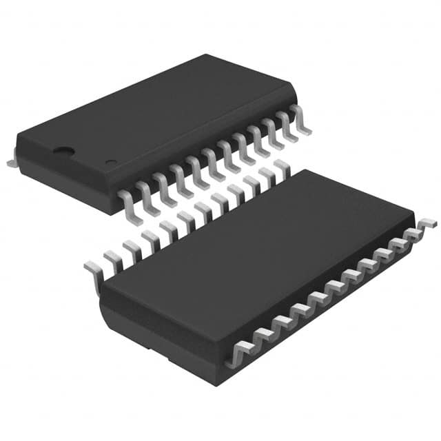
- Part No.:
- A6276SLW
- Manufacturer:
- Allegro MicroSystems
- Category:
- LED Drivers
- Package:
- 24-SOIC (0.295", 7.50mm Width)
- Datasheet:
-
 A6276SLW.pdf
- Description:
- IC LED DRVR LINEAR 75.5MA 24SOIC
- Quantity:
- Payment:

- Shipping:

Inventory:2,470
Please send an inquiry. Send us your inquiry, and we will respond immediately.
Product details
Overview
A6276SLW from Allegro MicroSystems is a 16-bit serial-input, constant-current latched LED driver in 24-pin SOICW package, featuring 16 NPN sink outputs with user-adjustable current (up to 90 mA per channel via REXT), 20 MHz serial data rate at 5 V logic supply, and active-low OUTPUT ENABLE for inter-digit blanking. It serves as the core driver IC in multiplexed LED display modules requiring precise current regulation and microprocessor interface.
For engineers reviewing the A6276SLW datasheet, A6276SLW pinout, A6276SLW application, or A6276SLW equivalent, key selection criteria include its –20°C to +85°C ambient rating, SOICW thermal resistance (RθJA = 85°C/W), undervoltage lockout (3.4–4.0 V), and compatibility with cascaded LED column drivers in industrial signage and instrumentation displays.
Technical Context
The A6276SLW integrates a 16-bit CMOS shift register, parallel latches, and 16 matched NPN constant-current sink drivers on a single BiCMOS die. Its serial-to-parallel conversion is triggered by LATCH ENABLE high, while OUTPUT ENABLE (active low) globally blanks all outputs without affecting latch state.
Current regulation is set externally via REXT at Pin 23, enabling precise per-channel sink current from 34.1 mA (REXT = 470 Ω) to 86.8 mA (REXT = 250 Ω) at VCE = 0.7 V. The device supports daisy-chaining via CMOS SERIAL DATA OUT (Pin 22) and exhibits propagation delays ≤1000 ns across CLOCK, LATCH, and ENABLE inputs.
Key Specifications
| Parameter | Value and Actual Design Meaning |
|---|---|
| Output Current | Up to 90 mA per channel; set by external REXT, enabling consistent brightness across LED segments. |
| Serial Data Rate | 20 MHz max at 5 V; supports fast refresh in high-resolution LED matrices without microcontroller bottleneck. |
| Supply Voltage | 4.5–5.5 V; includes undervoltage lockout (3.4–4.0 V) to prevent erratic operation during brownout. |
| Logic Interface | CMOS-compatible inputs/outputs; VIH ≥ 3.5 V, VIL ≤ 1.5 V at 5 V supply ensures noise margin in noisy industrial environments. |
| Thermal Resistance | RθJA = 85°C/W (SOICW); requires PCB copper area planning for >40 mA continuous per output at 85°C ambient. |
| Timing Tolerance | Data setup time 50 ns, hold time 20 ns; enables reliable operation with standard FPGA or MCU GPIO clocking. |
| Operating Temp | –20°C to +85°C ambient; narrower range than E-grade variants, suited for indoor commercial displays. |
Pinout & Package
24-pin SOICW (Small Outline Integrated Circuit, Wide-body) package with gull-wing leads, 1.27 mm pitch, and exposed thermal pad not present (unlike LP variant). Dimensions: 15.40 × 7.50 × 2.65 mm (L × W × H).
| Pin/Terminal | Circuit Role | Design Meaning |
|---|---|---|
| 1 | GND | Common reference for logic and power grounds; must be low-impedance to avoid latch misfires from ground bounce. |
| 2 | SERIAL DATA IN | CMOS input accepting microcontroller SPI/MCU GPIO serial stream; no internal pull-up/down. |
| 3 | CLOCK | Rising-edge-triggered shift register clock; 10 MHz max recommended for cascade stability. |
| 4 | LATCH ENABLE | High-level strobe to transfer shift register contents to output latches; held high for transparent mode. |
| 5–20 | OUT0–OUT15 | 16 NPN open-collector sink outputs; each drives one LED cathode with constant current set by REXT. |
| 21 | OUTPUT ENABLE | Active-low global blanking control; high = all outputs OFF, independent of latch state. |
| 22 | SERIAL DATA OUT | CMOS output for daisy-chaining; connects to SERDATAIN of next A6276 in chain. |
| 23 | REXT | Reference terminal for external current-setting resistor; sets identical sink current for all 16 outputs. |
| 24 | SUPPLY (VDD) | 5 V logic supply input; powers shift register, latches, and bias circuitry-not LED load path. |
Key Features
| Feature | Design Value |
|---|---|
| 16-channel constant-current sink | Enables uniform LED brightness without per-channel resistors; matching ±1.5% typical reduces segment luminance variance. |
| Undervoltage lockout (UVLO) | Prevents partial register updates and output glitches during power ramp-up or brownout below 3.4 V. |
| Cascadable serial interface | SERIAL DATA OUT allows unlimited expansion of LED columns using single MCU SPI line and shared CLOCK/LATCH. |
| Inter-digit blanking | OUTPUT ENABLE (Pin 21) provides hardware-level blanking for multiplexed displays without software overhead. |
| BiCMOS process | Combines low-power CMOS logic (0.8–15 mA IDD) with robust NPN output drivers capable of 90 mA sink per pin. |
Applications
| Industrial Panel Meters | Commercial LED Signage |
|---|---|
Use Scenario: Driving 7-segment or 14-segment alphanumeric displays in factory HMIs with 1/8 or 1/16 multiplexing. IC Role / Device Role / Timing Role: Constant-current sink driver for LED digit cathodes; handles serial data loading and blanking synchronization via LATCH ENABLE and OUTPUT ENABLE. Use Value: Eliminates need for 16 discrete current-limiting resistors; UVLO prevents display corruption during AC line dips common in industrial settings. | Use Scenario: Controlling red/green LED pixel columns in outdoor message boards with ambient temperature up to 85°C. IC Role / Device Role / Timing Role: Column driver in passive-matrix LED array; uses daisy-chained SERIAL DATA OUT to scale to hundreds of LEDs with minimal MCU pins. Use Value: SOICW package fits compact PCB layouts; 90 mA per channel supports high-brightness red LEDs even at elevated ambient temperatures. |
| Test Equipment Displays | Appliance Control Panels |
Use Scenario: Driving segmented bar-graph or status indicator LEDs on benchtop oscilloscopes and power analyzers. IC Role / Device Role / Timing Role: Serial-input latched driver interfacing directly with test equipment microcontrollers; LATCH ENABLE synchronized to system update cycle. Use Value: Low logic power (≤15 mA IDD) minimizes self-heating in sealed enclosures; 20 MHz data rate enables rapid display updates during measurement sweeps. | Use Scenario: Illuminating function buttons and status icons on microwave ovens and washing machine control panels. IC Role / Device Role / Timing Role: LED driver for user-interface backlighting; OUTPUT ENABLE used for sleep-mode blanking to reduce standby power. Use Value: –20°C to +85°C rating covers appliance thermal cycling; lead-free SOICW meets RoHS compliance for consumer goods. |
Equivalent & Alternatives
The following parts are listed as comparable options for similar constant-current LED driver applications.
| Alternative Part | Technical Difference | Application Difference | Selection Advice |
|---|---|---|---|
| TB62706BF | Pin-compatible 16-bit sink driver; identical pinout and REXT-based current control but lacks UVLO and has lower max current (60 mA). | Used in legacy Japanese display systems; no inter-digit blanking via dedicated OE pin-requires software-controlled blanking. | Select TB62706BF only if replacing existing designs where UVLO is unused and 60 mA suffices. |
| A6275ELWTR-T | 8-bit version in same SOICW package; half the channel count, identical electrical specs, and same –20°C to +85°C rating. | Suitable for smaller displays or dual-driver configurations where space permits two ICs instead of one 16-bit unit. | Choose A6275ELWTR-T when board layout favors modular 8-bit sections or when thermal budget limits total dissipation. |
Compared with TB62706BF, A6276SLW adds undervoltage lockout and higher current capability, improving reliability in fluctuating supplies; versus A6275ELWTR-T, it halves component count for 16-bit displays but increases thermal load per package-requiring careful SOICW copper pour design.
Availability
A6276SLW is available at Aetrix Electronics and suitable for industrial panel meters, commercial LED signage, and appliance control panels requiring stable component supply despite its Last Time Buy status.
Supply support for A6276SLW includes scheduled delivery planning, volume procurement assistance, BOM continuity management, traceable sourcing, and lifecycle availability coordination for OEM customers, industrial embedded developers, connected-device designers, and electronics production programs.
Manufacturer
Allegro MicroSystems is a U.S.-based designer of high-performance magnetic sensors and power ICs, headquartered in Worcester, Massachusetts.
The A6276 product line delivers integrated LED driver solutions optimized for multiplexed alphanumeric and graphic displays in industrial and commercial equipment.
FAQ
What is the maximum allowable output current per channel for A6276SLW?
The A6276SLW supports up to 90 mA constant-current sink per output (Pins 5–20) when configured with REXT = 250 Ω and VCE = 0.7 V. At 85°C ambient, derating applies: continuous 90 mA is achievable only with adequate PCB copper area due to its SOICW RθJA of 85°C/W. For sustained full-load operation, thermal simulation using PD(act) = DC × (VCE × IO × 16) + (VDD × IDD) is recommended before finalizing layout.
Does A6276SLW support daisy-chaining with other LED drivers?
Yes, A6276SLW supports daisy-chaining via its CMOS SERIAL DATA OUT (Pin 22), which connects directly to the SERIAL DATA IN of the next A6276SLW or compatible device. This enables scalable LED column expansion without additional MCU GPIOs. The 20 MHz max data rate and 40 ns CLOCK-to-SERIAL DATA OUT delay ensure timing integrity across chains of up to 10+ devices when using proper PCB trace length matching and termination.
What is the purpose of the REXT pin on A6276SLW?
The REXT pin (Pin 23) on A6276SLW connects to an external resistor that sets the constant-current value for all 16 output drivers simultaneously. With REXT = 250 Ω, typical output current is 75.5 mA per channel at VCE = 0.7 V; with REXT = 470 Ω, it drops to 40.0 mA. This single-resistor calibration eliminates per-channel trimming, simplifies BOM, and ensures tight current matching (±1.5% typical) across all outputs-critical for uniform LED brightness in displays.
How does the OUTPUT ENABLE function work on A6276SLW?
The OUTPUT ENABLE pin (Pin 21) on A6276SLW is an active-low control that globally disables all 16 output drivers (Pins 5–20) without altering the data stored in the latches. When high, outputs are blanked (OFF); when low, outputs reflect their latched states. This enables hardware-based inter-digit blanking in multiplexed LED displays, eliminating software delays and ensuring precise timing control-especially valuable in high-refresh-rate applications like oscilloscope graticules or real-time status indicators.
Is A6276SLW compatible with 3.3 V microcontrollers?
A6276SLW requires a 4.5–5.5 V logic supply (VDD = 5 V typical) and is not 3.3 V logic-compatible. Its VIH threshold is 0.7×VDD (≥3.5 V), and VIL is ≤0.3×VDD (≤1.5 V), making direct connection to 3.3 V MCU GPIOs unsafe without level translation. A6276SLW must be driven by 5 V-tolerant outputs or paired with a dual-supply level shifter (e.g., TXB0108) to interface reliably with 3.3 V microcontrollers while preserving timing margins and noise immunity.
A6276SLW Specifications
- Product attributes
- Attribute value
- Manufacturer:
- Allegro MicroSystems
- Series:
- -
- Package/Case:
- 24-SOIC (0.295", 7.50mm Width)
- Packaging:
- Tube
- Product Status:
- Obsolete
- Type:
- Linear
- Topology:
- Shift Register
- Internal Switch(s):
- Yes
- Number of Outputs:
- 16
- Voltage - Supply (Min):
- 4.5V
- Voltage - Supply (Max):
- 5.5V
- Voltage - Output:
- 4V
- Current - Output / Channel:
- 75.5mA
- Frequency:
- 20MHz
- Dimming:
- -
- Applications:
- -
- Operating Temperature:
- -20°C ~ 85°C (TA)
- Grade:
- -
- Qualification:
- -
- Mounting Type:
- Surface Mount
- Supplier Device Package:
- 24-SOIC
A6276SLW FAQ
1.How can I place an order for A6276SLW through Aetrix?
Please submit a Request for Quotation (RFQ) for A6276SLW on Aetrix. Our sales agent will provide a competitive quotation and guide you through the order confirmation once you accept the terms.
2.Are the price and stock information for A6276SLW reliable?
The price and inventory of A6276SLW are updated periodically and may fluctuate due to market conditions. Stock and pricing data are typically refreshed every 24 hours. Quotation validity for A6276SLW is usually 5 days.
3.What payment methods are accepted for A6276SLW?
We accept Wire Transfer, PayPal, Credit Card, Western Union, MoneyGram, and Escrow for A6276SLW transactions.
Note: Certain payment methods may incur a processing fee.
4.How is shipping managed for A6276SLW?
A6276SLW orders can be shipped via leading logistics carriers, including DHL, UPS, FedEx, TNT, or Registered Mail.
Once your A6276SLW order is processed, you will receive an email with the shipment details and tracking number.
Note: Tracking information may take up to 24 hours to appear. Express delivery typically takes 3–5 business days.
5.How can I obtain technical support or documentation for A6276SLW?
For technical support, including A6276SLW datasheets, pinout diagrams, or application guidance, please contact our engineering support team. They can provide detailed documentation and assistance for your A6276SLW requirements.
6.How does Aetrix verify that A6276SLW is sourced from the original manufacturer or authorized distributors?
All A6276SLW products on Aetrix are procured from qualified distributors and authorized channels. Our dedicated quality assurance team conducts strict verification, including traceability checks and, if necessary, third-party testing. This ensures that A6276SLW meets industry standards.
7.What is the process for return or replacement of A6276SLW?
All A6276SLW units undergo pre-shipment inspection (PSI). If there is an issue with A6276SLW, returns or replacements are accepted under the following conditions:
1.Quantity discrepancies, incorrect items, or visible external defects (such as breakage or corrosion), acknowledged by Aetrix.
2.The issue is reported within 90 days of delivery.
3.The A6276SLW part is unused and in its original packaging.
Return procedure for A6276SLW:
1.Submit a request within 90 days.
2.Obtain a Return Material Authorization (RMA) from Aetrix.
A6276SLW Tags

-
BCR402RE6327HTSA1
Infineon Technologies

-
BCR430UXTSA2
Infineon Technologies

-
BCR420UE6433HTMA1
Infineon Technologies
-
BCR420UE6327HTSA1
Infineon Technologies
-
BCR421UE6327HTSA1
Infineon Technologies

-
LYT1604D-TL
Power Integrations

-
HV9910CLG-G
Microchip Technology

-
CL2N8-G
Microchip Technology

-
BCR420UW6-7
Diodes Incorporated
-
BCR421UW6-7
Diodes Incorporated

-
BCR420UFD-7
Diodes Incorporated
-
BCR421UFD-7
Diodes Incorporated
Tech Hub

A practical engineering and sourcing framework covering lifecycle verification, lifetime-buy calculations, replacement qualification, supplier checks and counterfeit-risk controls.

TTL and CMOS logic families differ in thresholds, loading, output drive, power and timing. This engineering guide compares 74HC and 74HCT, calculates noise margins and checks 3.3 V/5 V compatibility.

A practical engineering guide to 3.3V and 5V logic compatibility, input thresholds, resistor dividers, translator ICs, MOSFET level shifting, I2C pull-ups, timing limits and power-sequencing risks.

The 74HC595 uses push-pull logic outputs, while the TPIC6B595 uses 50 V open-drain DMOS sinks for higher-power loads. This guide compares timing, current limits, 3.3 V interfacing, load wiring, thermal…

The 74HC595 converts serial data into eight stable parallel outputs. This guide covers pin functions, shift and storage timing, OE and MR behavior, drive-current limits, cascading, voltage compatibilit…

A technical comparison of level-sensitive latches and edge-triggered flip-flops, covering timing windows, setup and hold limits, master–slave operation, time borrowing, race-through, HDL inference and…

A D latch stores one bit while Enable controls when data can pass. This reference covers gate-level operation, truth tables, transparency, setup and hold timing, LE versus OE, common ICs and practical …

An SR latch stores one bit through cross-coupled feedback. This engineering reference covers NOR and NAND implementations, truth tables, forbidden-state recovery, gated operation, switch debouncing, fa…

Latch circuits retain one bit through feedback. This technical reference covers SR and D latches, truth tables, transparency, timing limits, latch-versus-flip-flop behavior, applications and common log…

An engineering guide to LED driver operation, constant-current and constant-voltage outputs, linear and switching topologies, dimming, IC selection, calculations, replacement compatibility, and fault c…


