
 My Inquiry
 My Account


Allegro MicroSystems A6276SLWTR-T
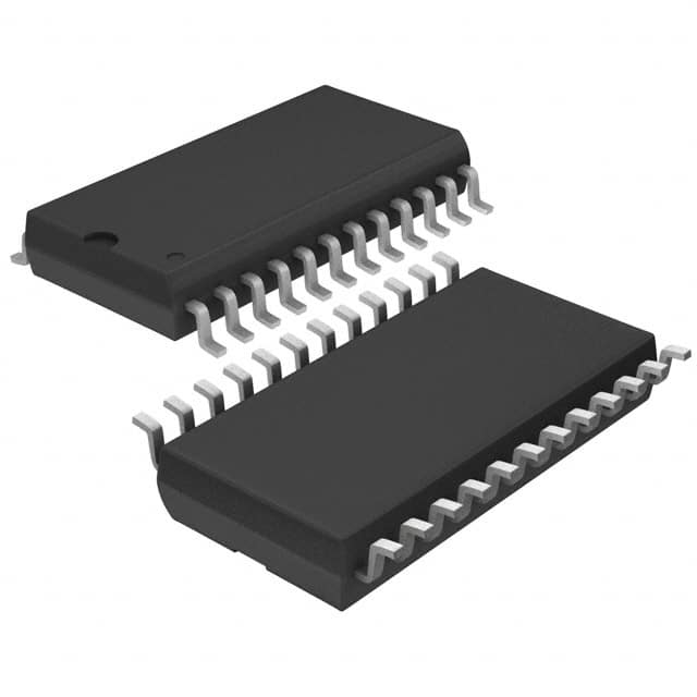
- Part No.:
- A6276SLWTR-T
- Manufacturer:
- Allegro MicroSystems
- Category:
- LED Drivers
- Package:
- 24-SOIC (0.295", 7.50mm Width)
- Datasheet:
-
 A6276SLWTR-T.pdf
- Description:
- IC LED DRVR LINEAR 75.5MA 24SOIC
- Quantity:
- Payment:

- Shipping:

Inventory:1,202
Please send an inquiry. Send us your inquiry, and we will respond immediately.
Product details
Overview
A6276SLWTR-T from Allegro MicroSystems is a 16-bit serial-input constant-current latched LED driver in 24-pin SOICW package, featuring 16 NPN sink drivers with user-adjustable current (up to 90 mA per output), 5 V logic compatibility, and CMOS serial data output for cascading. It serves as the core driver in multiplexed LED display modules requiring precise current control and microprocessor interface.
For engineers reviewing the A6276SLWTR-T datasheet, A6276SLWTR-T pinout, A6276SLWTR-T application, or A6276SLWTR-T equivalent, this page delivers verified technical context, thermal derating guidance for SOICW packaging, latch timing constraints, undervoltage lockout behavior at 3.4–4.0 V, and real-world current-setting resistor relationships (e.g., 250 Ω → 75.5 mA typ).
Technical Context
The A6276SLWTR-T integrates a 16-bit CMOS shift register, parallel latches, and 16 matched NPN constant-current sink drivers - all operating from a single 4.5–5.5 V supply. Its ENABLE input (active-low) provides inter-digit blanking, while SERIAL DATA OUT enables daisy-chaining without external logic.
Current regulation is set externally via REXT, with output matching ±1.5% (typ) across outputs at fixed VCE. The device implements undervoltage lockout (UVLO) that disables operation below ~3.7 V, preventing erratic latch behavior during power ramp-up.
Key Specifications
| Parameter | Value and Actual Design Meaning |
|---|---|
| Output Current | Up to 90 mA per channel (absolute max); typical 75.5 mA @ VCE = 0.7 V, REXT = 250 Ω - sets LED brightness and thermal load. |
| Logic Supply | 4.5–5.5 V - compatible with standard 5 V microcontrollers; supports up to 20 MHz serial data rate. |
| UVLO Threshold | 3.4–4.0 V - prevents partial operation during brown-out; device resets cleanly when VDD rises above threshold. |
| Thermal Resistance | RθJA = 85 °C/W (SOICW, 1-layer JEDEC PCB) - requires derating above 25°C ambient; max continuous current drops to ~40 mA at 85°C. |
| Propagation Delay | 300–1000 ns (CLOCK/LATCH/ENABLE to OUT) - defines minimum clock period (≥100 ns) for reliable 10 MHz cascade operation. |
| Output Leakage | ≤5.0 μA @ VOH = 15 V - ensures minimal false turn-on in high-impedance or open-circuit LED conditions. |
| Serial Data Rate | Up to 20 MHz (5 V logic) - enables fast refresh of large LED matrices (e.g., 16×16 segments in <1.3 ms). |
Pinout & Package
Package: 24-pin SOICW (wide-body), RoHS-compliant, matte tin-plated leadframe, exposed pad not present (unlike LP variant). Dimensions: 15.40 × 7.50 × 2.65 mm (L × W × H), pitch 1.27 mm.
| Pin/Terminal | Circuit Role | Design Meaning |
|---|---|---|
| 1 | GND | Common reference for logic and output sinks; must be low-impedance to avoid latch noise coupling. |
| 2 | SERIAL DATA IN | CMOS-level serial input; data shifted on rising clock edge; requires ≥50 ns setup before clock. |
| 3 | CLOCK | Rising-edge-triggered shift register clock; max 10 MHz recommended for cascade stability. |
| 4 | LATCH ENABLE | Active-high strobe; transfers shift register contents to latches; must be held high ≥100 ns before clock edge. |
| 5–20 | OUT0–OUT15 | 16 NPN current-sink outputs; each drives one LED cathode; voltage drop ≤0.75 V at 90 mA. |
| 21 | OUTPUT ENABLE | Active-low global blanking; high = all outputs OFF (no current); does not affect latch state. |
| 22 | SERIAL DATA OUT | CMOS-level daisy-chain output; enables multi-device cascading without external buffers. |
| 23 | REXT | Reference terminal for external current-setting resistor; sets identical current for all 16 outputs. |
| 24 | SUPPLY (VDD) | 5 V logic supply; powers shift register, latches, and bias circuitry; UVLO monitors this node. |
Key Features
| Feature | Design Value |
|---|---|
| 16-channel constant-current sink | Single REXT sets identical current for all outputs (±1.5% matching), eliminating per-channel resistors. |
| CMOS serial interface | Direct connection to 5 V microcontrollers; no level-shifting needed; supports >10 MHz cascade clocking. |
| Inter-digit blanking | Active-low OUTPUT ENABLE allows synchronized digit blanking in multiplexed displays without software overhead. |
| Undervoltage lockout | Prevents metastable latch states during power-up/down; ensures deterministic reset below 3.7 V nominal. |
| Thermal robustness | SOICW package rated for –20 to +85°C ambient; RθJA = 85 °C/W enables stable 40 mA/channel at full temp range. |
Applications
| LED Matrix Displays | Industrial Panel Meters |
|---|---|
|
Use Scenario: Driving 16×8 segment LED arrays in factory HMIs with 1:8 multiplexing. IC Role / Device Role / Timing Role: Constant-current sink driver providing uniform brightness across all segments; handles serial data chaining across multiple A6276SLWTR-T devices. Use Value: Eliminates 128 individual current-limiting resistors; maintains ±1.5% current matching between segments for consistent luminance. |
Use Scenario: Numeric LED readouts in DIN-rail mounted power meters with isolated RS-485 communication. IC Role / Device Role / Timing Role: LED driver interfaced to an isolated microcontroller via optocoupled SPI lines; blanked during analog measurement cycles. Use Value: Active-low OUTPUT ENABLE synchronizes LED off-time with ADC sampling, reducing EMI and supply ripple coupling. |
| Point-of-Sale Terminals | Transportation Annunciators |
|
Use Scenario: Dual-line 16-segment alphanumeric displays in retail payment terminals with battery backup. IC Role / Device Role / Timing Role: Serial-input LED driver receiving display data over low-speed UART-to-SPI bridge; powered from 5 V rail. Use Value: UVLO ensures display remains blank during brown-out events, preventing corrupted or ghosted characters during power recovery. |
Use Scenario: Status indicator panels in railcar door control systems, operating in –20 to +70°C environments. IC Role / Device Role / Timing Role: Ruggedized LED driver handling vibration-prone wiring; outputs directly drive common-cathode LED clusters. Use Value: SOICW package meets industrial thermal requirements; 90 mA per channel supports high-brightness red/amber LEDs under wide-temp conditions. |
Equivalent & Alternatives
The following parts are listed as comparable options for similar constant-current LED driver applications.
| Alternative Part | Technical Difference | Application Difference | Selection Advice |
|---|---|---|---|
| TB62706BF | Pin-compatible 16-bit sink driver; identical SOICW-24 package; lacks UVLO and has higher RθJA (95 °C/W). | No built-in undervoltage protection; requires external reset supervision in brown-out-prone systems. | Choose TB62706BF only if UVLO is unnecessary and thermal margin exceeds 10°C at full load. |
| A6275ELWTR-T | 8-bit version in same SOICW-24 package; half the channel count; identical REXT current-setting and timing specs. | Requires two devices for 16-bit applications; increases board area and routing complexity. | Select A6275ELWTR-T only when design uses discrete 8-bit segments or needs independent current control per group. |
Compared with TB62706BF, A6276SLWTR-T adds critical UVLO for power integrity; compared with A6275ELWTR-T, it halves component count and interconnects for full 16-bit displays - directly reducing BOM cost and layout risk.
Availability
A6276SLWTR-T is available at Aetrix Electronics and suitable for LED matrix displays, industrial panel meters, and transportation annunciators requiring stable component supply despite its Last Time Buy status.
Supply support for A6276SLWTR-T includes scheduled delivery planning, volume procurement assistance, BOM continuity management, traceable sourcing, and lifecycle availability coordination for OEM customers, industrial embedded developers, connected-device designers, and electronics production programs.
Manufacturer
Allegro MicroSystems designs high-performance magnetic sensors and power ICs, headquartered in Worcester, Massachusetts, with focus on precision motion control and energy-efficient power interfaces.
The A6276 product line targets LED display systems requiring accurate, scalable current sinking with microprocessor serial control - optimized for reliability in industrial and commercial signage applications.
FAQ
What is the operating temperature range for A6276SLWTR-T?
The A6276SLWTR-T is rated for –20°C to +85°C ambient operation. This narrower range versus the E-grade (–40°C to +85°C) reflects its S-grade qualification, making it suitable for indoor commercial and non-automotive industrial environments where extreme cold start is not required. The A6276SLWTR-T thermal performance remains fully specified within this band, including RθJA = 85 °C/W and current derating curves.
How do I calculate the REXT value needed for a target LED current with A6276SLWTR-T?
Use the formula IO ≈ 12.5 V / REXT, derived from the internal 12.5 V reference and current mirror architecture. For example, to achieve 40 mA per output, select REXT = 12.5 V / 0.04 A = 312.5 Ω (standard 316 Ω 1% resistor yields ~39.6 mA). The A6276SLWTR-T datasheet confirms 40.0 mA typ at REXT = 470 Ω, validating this linear relationship across the 250–500 Ω range.
Does A6276SLWTR-T support daisy-chaining, and what are the timing limits?
Yes, A6276SLWTR-T supports daisy-chaining via its CMOS SERIAL DATA OUT pin, enabling multi-device cascades without external buffers. Maximum reliable cascade clock frequency is 10 MHz per device, with propagation delay (CLOCK to SERIAL DATA OUT) ≤40 ns. Total latency accumulates linearly: 3 devices require ≥120 ns minimum clock period to ensure valid data at the final device's SERIAL DATA IN.
What happens to the latched data when OUTPUT ENABLE is asserted high on A6276SLWTR-T?
When OUTPUT ENABLE is high on A6276SLWTR-T, all 16 output drivers are disabled (blanked), but the data stored in the internal latches remains fully intact and unaltered. The latches retain their state until new data is shifted and latched - meaning display content is preserved during blanking intervals, enabling flicker-free multiplexing and synchronized digit updates without retransmitting data.
Is A6276SLWTR-T pin-compatible with other A6276 variants like A6276ELWTR-T?
Yes, A6276SLWTR-T is fully pin-compatible with A6276ELWTR-T and all other LW-package variants - sharing identical 24-pin SOICW footprint, pin numbering, and electrical pin functions. The sole difference is ambient temperature rating: A6276SLWTR-T is S-grade (–20°C to +85°C), while A6276ELWTR-T is E-grade (–40°C to +85°C). No PCB or schematic changes are needed when substituting within the S-grade operating envelope.
A6276SLWTR-T Specifications
- Product attributes
- Attribute value
- Manufacturer:
- Allegro MicroSystems
- Series:
- -
- Package/Case:
- 24-SOIC (0.295", 7.50mm Width)
- Packaging:
- Tape & Reel (TR)
- Product Status:
- Obsolete
- Type:
- Linear
- Topology:
- Shift Register
- Internal Switch(s):
- Yes
- Number of Outputs:
- 16
- Voltage - Supply (Min):
- 4.5V
- Voltage - Supply (Max):
- 5.5V
- Voltage - Output:
- 4V
- Current - Output / Channel:
- 75.5mA
- Frequency:
- 20MHz
- Dimming:
- -
- Applications:
- -
- Operating Temperature:
- -20°C ~ 85°C (TA)
- Grade:
- -
- Qualification:
- -
- Mounting Type:
- Surface Mount
- Supplier Device Package:
- 24-SOIC
A6276SLWTR-T FAQ
1.How can I place an order for A6276SLWTR-T through Aetrix?
Please submit a Request for Quotation (RFQ) for A6276SLWTR-T on Aetrix. Our sales agent will provide a competitive quotation and guide you through the order confirmation once you accept the terms.
2.Are the price and stock information for A6276SLWTR-T reliable?
The price and inventory of A6276SLWTR-T are updated periodically and may fluctuate due to market conditions. Stock and pricing data are typically refreshed every 24 hours. Quotation validity for A6276SLWTR-T is usually 5 days.
3.What payment methods are accepted for A6276SLWTR-T?
We accept Wire Transfer, PayPal, Credit Card, Western Union, MoneyGram, and Escrow for A6276SLWTR-T transactions.
Note: Certain payment methods may incur a processing fee.
4.How is shipping managed for A6276SLWTR-T?
A6276SLWTR-T orders can be shipped via leading logistics carriers, including DHL, UPS, FedEx, TNT, or Registered Mail.
Once your A6276SLWTR-T order is processed, you will receive an email with the shipment details and tracking number.
Note: Tracking information may take up to 24 hours to appear. Express delivery typically takes 3–5 business days.
5.How can I obtain technical support or documentation for A6276SLWTR-T?
For technical support, including A6276SLWTR-T datasheets, pinout diagrams, or application guidance, please contact our engineering support team. They can provide detailed documentation and assistance for your A6276SLWTR-T requirements.
6.How does Aetrix verify that A6276SLWTR-T is sourced from the original manufacturer or authorized distributors?
All A6276SLWTR-T products on Aetrix are procured from qualified distributors and authorized channels. Our dedicated quality assurance team conducts strict verification, including traceability checks and, if necessary, third-party testing. This ensures that A6276SLWTR-T meets industry standards.
7.What is the process for return or replacement of A6276SLWTR-T?
All A6276SLWTR-T units undergo pre-shipment inspection (PSI). If there is an issue with A6276SLWTR-T, returns or replacements are accepted under the following conditions:
1.Quantity discrepancies, incorrect items, or visible external defects (such as breakage or corrosion), acknowledged by Aetrix.
2.The issue is reported within 90 days of delivery.
3.The A6276SLWTR-T part is unused and in its original packaging.
Return procedure for A6276SLWTR-T:
1.Submit a request within 90 days.
2.Obtain a Return Material Authorization (RMA) from Aetrix.
A6276SLWTR-T Tags

-
BCR402RE6327HTSA1
Infineon Technologies

-
BCR430UXTSA2
Infineon Technologies

-
BCR420UE6433HTMA1
Infineon Technologies
-
BCR420UE6327HTSA1
Infineon Technologies
-
BCR421UE6327HTSA1
Infineon Technologies

-
LYT1604D-TL
Power Integrations

-
HV9910CLG-G
Microchip Technology

-
CL2N8-G
Microchip Technology

-
BCR420UW6-7
Diodes Incorporated
-
BCR421UW6-7
Diodes Incorporated

-
BCR420UFD-7
Diodes Incorporated
-
BCR421UFD-7
Diodes Incorporated
Tech Hub

A practical engineering and sourcing framework covering lifecycle verification, lifetime-buy calculations, replacement qualification, supplier checks and counterfeit-risk controls.

TTL and CMOS logic families differ in thresholds, loading, output drive, power and timing. This engineering guide compares 74HC and 74HCT, calculates noise margins and checks 3.3 V/5 V compatibility.

A practical engineering guide to 3.3V and 5V logic compatibility, input thresholds, resistor dividers, translator ICs, MOSFET level shifting, I2C pull-ups, timing limits and power-sequencing risks.

The 74HC595 uses push-pull logic outputs, while the TPIC6B595 uses 50 V open-drain DMOS sinks for higher-power loads. This guide compares timing, current limits, 3.3 V interfacing, load wiring, thermal…

The 74HC595 converts serial data into eight stable parallel outputs. This guide covers pin functions, shift and storage timing, OE and MR behavior, drive-current limits, cascading, voltage compatibilit…

A technical comparison of level-sensitive latches and edge-triggered flip-flops, covering timing windows, setup and hold limits, master–slave operation, time borrowing, race-through, HDL inference and…

A D latch stores one bit while Enable controls when data can pass. This reference covers gate-level operation, truth tables, transparency, setup and hold timing, LE versus OE, common ICs and practical …

An SR latch stores one bit through cross-coupled feedback. This engineering reference covers NOR and NAND implementations, truth tables, forbidden-state recovery, gated operation, switch debouncing, fa…

Latch circuits retain one bit through feedback. This technical reference covers SR and D latches, truth tables, transparency, timing limits, latch-versus-flip-flop behavior, applications and common log…

An engineering guide to LED driver operation, constant-current and constant-voltage outputs, linear and switching topologies, dimming, IC selection, calculations, replacement compatibility, and fault c…


