
 My Inquiry
 My Account


Allegro MicroSystems A6277EA
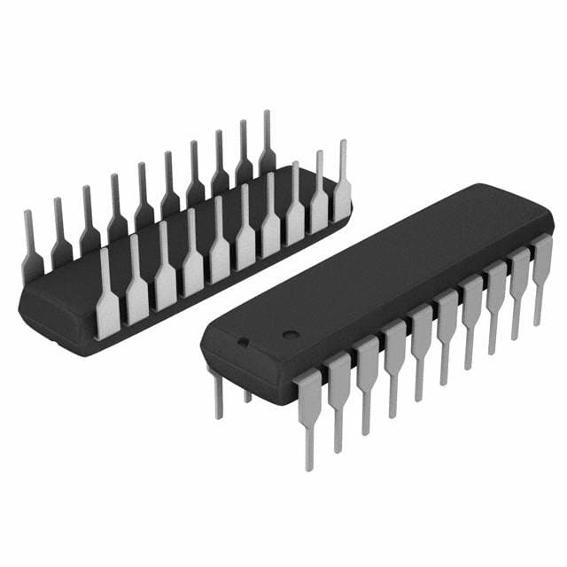
- Part No.:
- A6277EA
- Manufacturer:
- Allegro MicroSystems
- Category:
- LED Drivers
- Package:
- 20-DIP (0.300", 7.62mm)
- Datasheet:
-
 A6277EA.pdf
- Description:
- IC LED DRIVER LINEAR 120MA 20DIP
- Quantity:
- Payment:

- Shipping:

Inventory:2,923
Please send an inquiry. Send us your inquiry, and we will respond immediately.
Product details
Overview
A6277EA from Allegro MicroSystems is an 8-bit serial-input constant-current latched LED driver in a 20-pin DIP package, featuring eight NPN constant-current sink outputs (up to 150 mA per channel), CMOS shift register + latch architecture, and HIGH/LOW current-select function enabling 100% or 50% programmed current. It targets multiplexed LED display modules requiring precise current control and microprocessor interface.
For engineers reviewing the A6277EA datasheet, A6277EA pinout, A6277EA application, or A6277EA equivalent, key selection considerations include its 20 MHz max serial data rate at 5 V logic supply, user-programmable output current via single REXT, inter-digit blanking via active-low OUTPUT ENABLE, and thermal derating behavior across –40°C to +85°C ambient.
Technical Context
The A6277EA integrates a serial-shift register followed by parallel latches, allowing asynchronous data loading and synchronous output update on LATCH ENABLE high. Its BiCMOS design combines low-power CMOS logic with robust NPN sink drivers capable of 1.0 V saturation voltage at full load.
Current regulation is resistor-defined via terminal 19 (REXT), supporting programmable output currents from ~34 mA to 140 mA per channel depending on REXT value and VCE. The dual serial data outputs (SDO1 on rising clock edge, SDO2 on falling edge) enable seamless cascading without external timing alignment.
Key Specifications
| Parameter | Value and Actual Design Meaning |
|---|---|
| Output Configuration | Eight NPN constant-current sink drivers with independent latch control |
| Max Serial Data Rate | 20 MHz at VDD = 5 V - enables fast refresh for high-resolution LED matrices |
| Output Current Range | 34–140 mA per channel (REXT = 470 Ω to 160 Ω) - supports wide LED VF range including white/blue |
| Current Select Function | HIGH/LOW input selects 100% or 50% of programmed current - enables hardware-level dimming without PWM |
| Logic Supply Voltage | 4.5–5.5 V - compatible with standard 5 V microcontroller I/O and tolerant of rail variation |
| Operating Temperature | –40°C to +85°C (Range E) - qualified for industrial and outdoor LED signage environments |
| Package Thermal Resistance | RθJA = 60°C/W (DIP-A) - enables 122 mA continuous sink per output at 85°C ambient |
Pinout & Package
Package: 20-pin plastic DIP (suffix A), lead-free with 100% matte-tin plating, through-hole mount.
| Pin/Terminal | Circuit Role | Design Meaning |
|---|---|---|
| 1 | LOGIC GROUND | Reference for all digital inputs and internal CMOS logic; must be isolated from power ground to avoid noise coupling |
| 2 | SERIAL DATA IN | Serial data input to shift register; accepts standard CMOS-level signals up to 20 MHz |
| 3 | CLOCK | Rising-edge-triggered clock for shift register; minimum pulse width 50 ns |
| 4 | LATCH ENABLE | Active-high strobe that transfers shift register contents to output latches; allows asynchronous data load and synchronous update |
| 5 | HIGH/LOW (CURRENT) | Selects 100% (logic low) or 50% (logic high) of REXT-programmed current - provides coarse analog dimming |
| 6, 15 | POWER GROUND | Return path for all eight output drivers; separate from logic ground to minimize switching noise interference |
| 7–14 | OUT0–OUT7 | Constant-current sink terminals; each delivers precise current set by REXT and HIGH/LOW state |
| 16 | OUTPUT ENABLE | Active-low global blanking control; disables all outputs simultaneously for inter-digit or frame blanking |
| 17 | SERIAL OUT2 | CMOS serial output triggered on clock falling edge - used for daisy-chaining to next device |
| 18 | SERIAL OUT1 | CMOS serial output triggered on clock rising edge - supports dual-phase cascading topologies |
| 19 | REXT | Connection point for external current-setting resistor; sets identical current for all eight outputs |
| 20 | LOGIC SUPPLY (VDD) | 5 V nominal CMOS logic supply; powers shift register, latches, and input buffers |
Key Features
| Feature | Design Value |
|---|---|
| Resistor-Programmed Constant Current | Single REXT sets identical sink current for all 8 outputs - simplifies BOM and eliminates per-channel calibration |
| Dual Serial Data Outputs | SDO1 (rising edge) and SDO2 (falling edge) enable glitch-free cascading without added delay compensation |
| Hardware Dimming Control | HIGH/LOW pin provides immediate 2× current scaling - reduces software overhead versus PWM-based dimming |
| Inter-Digit Blanking | Active-low OUTPUT ENABLE disables all outputs simultaneously - essential for time-multiplexed LED displays |
| Undervoltage Lockout | VDD(UV) = 4.3 V typical - prevents erratic operation during power ramp-up or brownout conditions |
Applications
| LED Matrix Displays | Industrial Panel Meters |
|---|---|
|
Use Scenario: Driving 8×8 or 16×8 red/green LED dot-matrix panels in outdoor kiosks or transit signage. IC Role / Device Role: Constant-current sink driver for column (or row) scanning, synchronized via microcontroller SPI interface. Use Value: Eliminates per-LED current-limiting resistors; maintains consistent brightness across temperature with ±6% current matching. |
Use Scenario: Controlling segmented LED indicators on factory HMIs where reliability and long-term stability are critical. IC Role / Device Role: Latched LED driver with local blanking control, interfaced to 8051 or ARM-based controller via GPIO bit-banging. Use Value: Built-in latches hold display state during controller interrupts; undervoltage lockout prevents display corruption during power dips. |
| Automotive Instrument Clusters | Point-of-Sale Display Modules |
|
Use Scenario: Driving multi-color LED segments in vehicle speedometers and fuel gauges operating across –40°C to +85°C. IC Role / Device Role: High-side referenced LED sink driver with thermal-aware current regulation and inter-digit blanking. Use Value: 60°C/W thermal resistance enables full 122 mA per output at 85°C ambient - avoids external heatsinking in compact clusters. |
Use Scenario: Powering alphanumeric LED displays in retail checkout systems requiring low-cost, high-reliability drive. IC Role / Device Role: Serial-to-parallel LED driver with integrated current regulation and cascade capability for multi-digit expansion. Use Value: Dual SDO outputs allow daisy-chaining up to 16 digits using single microcontroller SPI port - reduces GPIO count and PCB routing complexity. |
Equivalent & Alternatives
The following parts are listed as comparable options for similar constant-current LED driver applications.
| Alternative Part | Technical Difference | Application Difference | Selection Advice |
|---|---|---|---|
| Toshiba TD62715FN | Pin-compatible 20-pin DIP; identical functional block diagram and REXT-based current programming; slightly lower max output current (120 mA vs. 150 mA) | Same LED matrix and panel meter use cases; requires verification of thermal performance at 85°C ambient due to higher RθJA | Preferred where legacy Toshiba sourcing or second-source qualification is required; verify VCE(sat) derating at high duty cycles. |
| ON Semiconductor CAT4016 | 16-pin SOIC; 16-channel sink driver; I²C interface instead of serial shift register; fixed 20 mA per channel (no REXT adjustment) | Better suited for low-current indicator LEDs; not suitable for high-brightness white/blue LED arrays requiring >30 mA per segment | Consider only for new designs targeting standardized low-current indicators and I²C bus integration - not a drop-in replacement for A6277EA. |
Compared with TD62715FN and CAT4016, the A6277EA offers higher per-channel current headroom (150 mA), resistor-based current tuning flexibility, and dual-edge serial outputs for deterministic cascading - making it optimal for demanding LED signage and automotive cluster applications where brightness consistency and thermal margin are critical.
Availability
A6277EA is available at Aetrix Electronics and suitable for LED matrix displays, industrial panel meters, automotive instrument clusters, and point-of-sale display modules requiring stable component supply and long-term industrial availability.
Supply support for A6277EA includes scheduled delivery planning, volume procurement assistance, BOM continuity management, traceable sourcing, and lifecycle availability coordination for OEM customers, industrial embedded developers, connected-device designers, and electronics production programs.
Manufacturer
Allegro MicroSystems is a U.S.-based designer and manufacturer of high-performance magnetic sensors, motor driver ICs, and precision power ICs, headquartered in Worcester, Massachusetts.
The A6277EA belongs to Allegro's constant-current LED driver product line, engineered specifically for high-reliability, thermally robust LED display systems in industrial and transportation environments.
FAQ
What is the maximum continuous output current per channel for the A6277EA at 85°C ambient?
The A6277EA can continuously sink 122 mA per output at 85°C ambient when mounted on a 1-layer PCB (RθJA = 60°C/W), with VCE ≤ 1.0 V. This rating is validated per Allegro's thermal derating curves and assumes proper PCB copper area and airflow. At lower ambient temperatures or with enhanced cooling, the A6277EA supports up to 150 mA per channel as specified in absolute maximum ratings.
How does the HIGH/LOW pin affect current regulation in the A6277EA?
The HIGH/LOW pin on the A6277EA provides hardware-selectable current scaling: a logic low applies 100% of the REXT-programmed current to all eight outputs, while a logic high reduces output current to 50% of that value. This function operates independently of the latches and OUTPUT ENABLE, enabling rapid brightness adjustment without reprogramming REXT or altering serial data flow - a feature unique to the A6277EA among its class.
Can the A6277EA be used with white or blue LEDs requiring forward voltages above 3.5 V?
Yes, the A6277EA supports white and blue LEDs (VF = 3.5–4.0 V) when paired with an external voltage dropper (e.g., Zener diode or series resistor) between the LED anode and supply rail. Because the A6277EA's VCE is typically 0.4–0.7 V, minimizing total drop across the driver reduces package power dissipation - critical for maintaining thermal stability in high-VF LED applications using the A6277EA.
What is the purpose of separating LOGIC GROUND (pin 1) and POWER GROUND (pins 6 & 15) on the A6277EA?
The A6277EA separates LOGIC GROUND and POWER GROUND to prevent switching noise from high-current outputs from corrupting sensitive CMOS inputs (CLOCK, LATCH ENABLE, SERIAL DATA IN). If both grounds share a common trace with significant impedance, voltage spikes exceeding 2.5 V on logic inputs relative to system ground may cause mislatching or clock errors - a failure mode explicitly documented in the A6277EA application notes.
Is the A6277EA still in active production, and what is its obsolescence status?
The A6277EA variant is classified as LAST TIME BUY per Allegro's November 2009 notice: it remains available for existing customer applications but is obsolete for new designs, with final order deadline April 30, 2010. Aetrix Electronics maintains legacy inventory and supports continuity planning for ongoing production, but recommends evaluating alternatives like TD62715FN for new designs requiring long-term supply assurance.
A6277EA Specifications
- Product attributes
- Attribute value
- Manufacturer:
- Allegro MicroSystems
- Series:
- -
- Package/Case:
- 20-DIP (0.300", 7.62mm)
- Packaging:
- Tube
- Product Status:
- Obsolete
- Type:
- Linear
- Topology:
- Shift Register
- Internal Switch(s):
- Yes
- Number of Outputs:
- 8
- Voltage - Supply (Min):
- 4.5V
- Voltage - Supply (Max):
- 5.5V
- Voltage - Output:
- 4V
- Current - Output / Channel:
- 120mA
- Frequency:
- 20MHz
- Dimming:
- -
- Applications:
- -
- Operating Temperature:
- -40°C ~ 85°C (TA)
- Grade:
- -
- Qualification:
- -
- Mounting Type:
- Through Hole
- Supplier Device Package:
- 20-DIP
A6277EA FAQ
1.How can I place an order for A6277EA through Aetrix?
Please submit a Request for Quotation (RFQ) for A6277EA on Aetrix. Our sales agent will provide a competitive quotation and guide you through the order confirmation once you accept the terms.
2.Are the price and stock information for A6277EA reliable?
The price and inventory of A6277EA are updated periodically and may fluctuate due to market conditions. Stock and pricing data are typically refreshed every 24 hours. Quotation validity for A6277EA is usually 5 days.
3.What payment methods are accepted for A6277EA?
We accept Wire Transfer, PayPal, Credit Card, Western Union, MoneyGram, and Escrow for A6277EA transactions.
Note: Certain payment methods may incur a processing fee.
4.How is shipping managed for A6277EA?
A6277EA orders can be shipped via leading logistics carriers, including DHL, UPS, FedEx, TNT, or Registered Mail.
Once your A6277EA order is processed, you will receive an email with the shipment details and tracking number.
Note: Tracking information may take up to 24 hours to appear. Express delivery typically takes 3–5 business days.
5.How can I obtain technical support or documentation for A6277EA?
For technical support, including A6277EA datasheets, pinout diagrams, or application guidance, please contact our engineering support team. They can provide detailed documentation and assistance for your A6277EA requirements.
6.How does Aetrix verify that A6277EA is sourced from the original manufacturer or authorized distributors?
All A6277EA products on Aetrix are procured from qualified distributors and authorized channels. Our dedicated quality assurance team conducts strict verification, including traceability checks and, if necessary, third-party testing. This ensures that A6277EA meets industry standards.
7.What is the process for return or replacement of A6277EA?
All A6277EA units undergo pre-shipment inspection (PSI). If there is an issue with A6277EA, returns or replacements are accepted under the following conditions:
1.Quantity discrepancies, incorrect items, or visible external defects (such as breakage or corrosion), acknowledged by Aetrix.
2.The issue is reported within 90 days of delivery.
3.The A6277EA part is unused and in its original packaging.
Return procedure for A6277EA:
1.Submit a request within 90 days.
2.Obtain a Return Material Authorization (RMA) from Aetrix.
A6277EA Tags

-
BCR402RE6327HTSA1
Infineon Technologies

-
BCR430UXTSA2
Infineon Technologies

-
BCR420UE6433HTMA1
Infineon Technologies
-
BCR420UE6327HTSA1
Infineon Technologies
-
BCR421UE6327HTSA1
Infineon Technologies

-
LYT1604D-TL
Power Integrations

-
HV9910CLG-G
Microchip Technology

-
CL2N8-G
Microchip Technology

-
BCR420UW6-7
Diodes Incorporated
-
BCR421UW6-7
Diodes Incorporated

-
BCR420UFD-7
Diodes Incorporated
-
BCR421UFD-7
Diodes Incorporated
Tech Hub

A practical engineering and sourcing framework covering lifecycle verification, lifetime-buy calculations, replacement qualification, supplier checks and counterfeit-risk controls.

TTL and CMOS logic families differ in thresholds, loading, output drive, power and timing. This engineering guide compares 74HC and 74HCT, calculates noise margins and checks 3.3 V/5 V compatibility.

A practical engineering guide to 3.3V and 5V logic compatibility, input thresholds, resistor dividers, translator ICs, MOSFET level shifting, I2C pull-ups, timing limits and power-sequencing risks.

The 74HC595 uses push-pull logic outputs, while the TPIC6B595 uses 50 V open-drain DMOS sinks for higher-power loads. This guide compares timing, current limits, 3.3 V interfacing, load wiring, thermal…

The 74HC595 converts serial data into eight stable parallel outputs. This guide covers pin functions, shift and storage timing, OE and MR behavior, drive-current limits, cascading, voltage compatibilit…

A technical comparison of level-sensitive latches and edge-triggered flip-flops, covering timing windows, setup and hold limits, master–slave operation, time borrowing, race-through, HDL inference and…

A D latch stores one bit while Enable controls when data can pass. This reference covers gate-level operation, truth tables, transparency, setup and hold timing, LE versus OE, common ICs and practical …

An SR latch stores one bit through cross-coupled feedback. This engineering reference covers NOR and NAND implementations, truth tables, forbidden-state recovery, gated operation, switch debouncing, fa…

Latch circuits retain one bit through feedback. This technical reference covers SR and D latches, truth tables, transparency, timing limits, latch-versus-flip-flop behavior, applications and common log…

An engineering guide to LED driver operation, constant-current and constant-voltage outputs, linear and switching topologies, dimming, IC selection, calculations, replacement compatibility, and fault c…


