
 My Inquiry
 My Account


Allegro MicroSystems A6279ELPTR-T
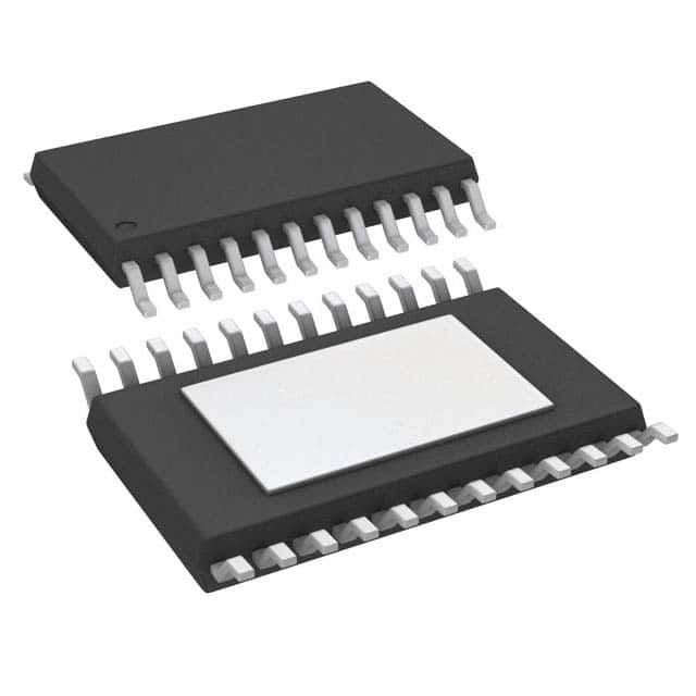
- Part No.:
- A6279ELPTR-T
- Manufacturer:
- Allegro MicroSystems
- Category:
- LED Drivers
- Package:
- 24-TSSOP (0.173", 4.40mm Width) Exposed Pad
- Datasheet:
-
 A6279ELPTR-T.pdf
- Description:
- IC LED DRVR LIN 75.5MA 24TSSOP
- Quantity:
- Payment:

- Shipping:

Inventory:2,296
Please send an inquiry. Send us your inquiry, and we will respond immediately.
Product details
Overview
A6279ELPTR-T from Allegro MicroSystems is a 16-channel serial-input constant-current latched LED driver with open-LED detection, designed for high-density LED display systems. It features 3.0–5.5 V logic supply operation, up to 90 mA per output, 20 ns output staggering delay, and CMOS serial data output for daisy-chaining. Used in industrial signage and automotive dashboard displays where reliable current sinking and fault reporting are critical.
For engineers reviewing the A6279ELPTR-T datasheet, A6279ELPTR-T pinout, A6279ELPTR-T application, or A6279ELPTR-T equivalent, key selection criteria include its 24-pin TSSOP-LP package with exposed thermal pad, REXT-based current programming, Schmitt-trigger noise immunity, and integrated UVLO/thermal shutdown - all essential for robust LED matrix control in temperature-variable environments.
Technical Context
The A6279ELPTR-T integrates a 16-bit BiCMOS shift register, parallel latches, and NPN constant-current sink drivers in a single monolithic IC. Its architecture supports microprocessor interfacing via 3.3 V or 5 V logic levels, with serial data rates up to 25 MHz and 20 ns inter-output staggering to suppress EMI.
Open-LED detection operates by monitoring VCE across each output against a 0.30 V threshold during test mode, reporting faults via SERIAL DATA OUT. Internal UVLO (2.15–2.85 V) and thermal shutdown (165 °C typical) ensure safe operation under supply or thermal stress.
Key Specifications
| Parameter | Value and Actual Design Meaning |
|---|---|
| Output channels | 16 independent constant-current sink outputs for driving LED segments or pixels |
| Max output current | 90 mA per channel, set externally via REXT resistor - enables precise brightness control |
| Logic supply range | 3.0–5.5 V - compatible with both 3.3 V and 5 V microcontrollers without level shifting |
| Open-LED detection | 0.30 V VCE threshold - reliably identifies open-circuit LEDs without external sensing circuitry |
| Staggering delay | 20 ns between consecutive outputs - reduces simultaneous switching current transients and EMI |
| Thermal shutdown | 165 °C junction temperature - protects device during overloads or poor heatsinking |
| Package type | 24-pin TSSOP with exposed thermal pad (LP suffix) - improves thermal dissipation for sustained 90 mA operation |
Pinout & Package
Package: 24-pin TSSOP with exposed thermal pad (LP), RoHS-compliant, 100% matte tin plated leadframe, 0.65 mm pitch, nominal height 1.20 mm.
| Pin/Terminal | Circuit Role | Design Meaning |
|---|---|---|
| 1, 2, 3, 4, 5–20, 22, 23, 24 | OUT0–OUT15, GND, SERIAL DATA IN, CLOCK, LATCH ENABLE | Standard digital I/O and 16 current-sink outputs - pins 5–20 map directly to OUT0–OUT15 |
| 13 | OUTPUT ENABLE (active low) | Global enable/disable of all 16 outputs - critical for blanking and power sequencing |
| 14 | SERIAL DATA OUT | CMOS-level output for cascading multiple A6279 devices or reading OCD error bits |
| 15 | REXT | Analog current-setting node - connects to external resistor to define sink current for all outputs |
| 16 | LOGIC SUPPLY (VDD) | Primary logic rail input - powers internal CMOS logic, shift register, and latches |
| EP (exposed pad) | Thermal ground / mechanical anchor | Must be soldered to PCB ground plane with thermal vias - lowers θJA to 28 °C/W |
Key Features
| Feature | Design Value |
|---|---|
| Schmitt-trigger inputs | 200–400 mV hysteresis on all digital inputs - rejects noise in electrically noisy display environments |
| Power-On Reset (POR) | Resets shift register and latches to zero at power-up - ensures predictable initial state |
| LED open-circuit detection | Dedicated test mode with serial readback of 16-bit error code - eliminates need for external diagnostics |
| Internal UVLO & TSD | Undervoltage lockout (2.15–2.85 V) and thermal shutdown (165 °C) - prevents erratic behavior during brownouts or overheating |
| Output staggering | 20 ns delay between adjacent outputs - limits peak ground current and simplifies decoupling design |
Applications
| Industrial LED Signage | Automotive Dashboard Displays |
|---|---|
Use Scenario: Outdoor variable-message signs requiring high-brightness, long-life LED arrays with real-time fault monitoring. IC Role / Device Role / Timing Role: Constant-current sink driver with open-LED detection - manages 16 LED segments per chip in multiplexed matrix configurations. Use Value: Enables automatic identification of failed LEDs without external sensors, reducing maintenance downtime and field service costs. | Use Scenario: Instrument cluster backlighting in vehicles where EMC compliance and thermal reliability are critical. IC Role / Device Role / Timing Role: Serial-controlled current sink with staggered outputs - drives segmented LCD backlights while minimizing conducted emissions. Use Value: 20 ns output staggering and integrated thermal shutdown meet automotive ASIL-B readiness requirements for functional safety. |
| Point-of-Sale Display Modules | Medical Equipment Status Panels |
Use Scenario: Compact retail kiosks needing dense, low-profile LED indicators with microcontroller-driven brightness control. IC Role / Device Role / Timing Role: Shift-register-based LED driver with REXT-programmable current - interfaces directly to 3.3 V MCU SPI peripherals. Use Value: Eliminates discrete current-limiting resistors per LED, reducing BOM count and PCB area by >70% versus discrete solutions. | Use Scenario: Diagnostic equipment status panels requiring fail-safe visual indication and regulatory-compliant fault reporting. IC Role / Device Role / Timing Role: Fault-aware LED driver with serial diagnostic readback - supports IEC 62304 software safety classification. Use Value: Open-LED detection data can be logged and reported via host MCU, satisfying traceability and self-test requirements in Class II medical devices. |
Equivalent & Alternatives
The following parts are listed as comparable options for similar constant-current LED driver applications.
| Alternative Part | Technical Difference | Application Difference | Selection Advice |
|---|---|---|---|
| TLC59283DBQR | 16-channel, 45 mA max per channel, no open-LED detection, 3.3 V only logic supply | Lacks fault reporting and thermal shutdown; limited drive strength for high-brightness LEDs | Choose when cost sensitivity outweighs diagnostic capability and higher current is unnecessary |
| MAX7219CWG+ | 8-digit/64-segment display driver with built-in BCD decode, 40 mA per segment, SPI interface | Integrated display controller architecture - not a general-purpose sink driver; fixed 8×8 mapping | Prefer for numeric LED displays with minimal MCU overhead; avoid for custom matrix or analog current tuning |
Compared with TLC59283DBQR and MAX7219CWG+, the A6279ELPTR-T delivers higher per-channel current (90 mA vs. 45/40 mA), integrated open-LED diagnostics, and dual-voltage logic compatibility - making it uniquely suited for industrial and automotive LED arrays demanding reliability and serviceability.
Availability
A6279ELPTR-T is available at Aetrix Electronics and suitable for industrial signage, automotive dashboard displays, and medical status panels requiring stable component supply and long-term production continuity.
Supply support for A6279ELPTR-T includes scheduled delivery planning, volume procurement assistance, BOM continuity management, traceable sourcing, and lifecycle availability coordination for OEM customers, industrial embedded developers, connected-device designers, and electronics production programs.
Manufacturer
Allegro MicroSystems is a U.S.-based designer and manufacturer of high-performance magnetic sensors and power ICs, founded in 1989 and headquartered in Worcester, Massachusetts.
The A6279 product line targets LED display systems requiring integrated current regulation, fault diagnostics, and robust serial control - emphasizing reliability in temperature-variable and EMI-sensitive environments.
FAQ
What is the maximum output current per channel for the A6279ELPTR-T?
The A6279ELPTR-T supports up to 90 mA per output channel when configured with an appropriate REXT resistor (e.g., 225 Ω at VCE = 0.7 V). Current is programmable and remains stable across VLED and temperature variations. The A6279ELPTR-T's 16-channel architecture maintains this rating across all outputs simultaneously under proper thermal management.
Does the A6279ELPTR-T support daisy-chaining with other LED drivers?
Yes, the A6279ELPTR-T includes a CMOS SERIAL DATA OUT pin that allows direct cascading to the SERIAL DATA IN of another A6279ELPTR-T or compatible device. This enables expansion beyond 16 outputs without additional MCU GPIOs, maintaining full open-LED detection functionality across the chain.
How does open-LED detection work on the A6279ELPTR-T?
The A6279ELPTR-T detects open LEDs by measuring VCE during dedicated test mode: if VCE falls below 0.30 V while the output is enabled, a '0' error bit is set. These 16 bits are serially readable via the SERIAL DATA OUT pin after three CLOCK pulses with OUTPUT ENABLE held low - enabling host MCU-based fault localization without external circuitry.
What package type is used for the A6279ELPTR-T, and why is the exposed pad important?
The A6279ELPTR-T uses a 24-pin TSSOP with exposed thermal pad (LP package). The EP pad must be soldered to a PCB ground plane with thermal vias to achieve the specified θJA of 28 °C/W. Without proper thermal anchoring, junction temperature rise may trigger thermal shutdown during sustained 90 mA operation - especially in enclosed or high-ambient environments.
Can the A6279ELPTR-T operate with a 3.3 V microcontroller interface?
Yes, the A6279ELPTR-T supports 3.3 V logic levels: its VIH threshold is 0.7×VDD and VIL is 0.3×VDD, with Schmitt-trigger inputs providing 200–400 mV hysteresis. When powered from a 3.3 V VDD, it accepts standard 3.3 V MCU signals directly - no level shifters required for SERIAL DATA IN, CLOCK, LATCH ENABLE, or OUTPUT ENABLE.
A6279ELPTR-T Specifications
- Product attributes
- Attribute value
- Manufacturer:
- Allegro MicroSystems
- Series:
- -
- Package/Case:
- 24-TSSOP (0.173", 4.40mm Width) Exposed Pad
- Packaging:
- Tape & Reel (TR)
- Product Status:
- Obsolete
- Type:
- Linear
- Topology:
- Shift Register
- Internal Switch(s):
- Yes
- Number of Outputs:
- 16
- Voltage - Supply (Min):
- 3V
- Voltage - Supply (Max):
- 5.5V
- Voltage - Output:
- -
- Current - Output / Channel:
- 75.5mA
- Frequency:
- 25MHz
- Dimming:
- -
- Applications:
- -
- Operating Temperature:
- -40°C ~ 85°C (TA)
- Grade:
- -
- Qualification:
- -
- Mounting Type:
- Surface Mount
- Supplier Device Package:
- 24-TSSOP-EP
A6279ELPTR-T FAQ
1.How can I place an order for A6279ELPTR-T through Aetrix?
Please submit a Request for Quotation (RFQ) for A6279ELPTR-T on Aetrix. Our sales agent will provide a competitive quotation and guide you through the order confirmation once you accept the terms.
2.Are the price and stock information for A6279ELPTR-T reliable?
The price and inventory of A6279ELPTR-T are updated periodically and may fluctuate due to market conditions. Stock and pricing data are typically refreshed every 24 hours. Quotation validity for A6279ELPTR-T is usually 5 days.
3.What payment methods are accepted for A6279ELPTR-T?
We accept Wire Transfer, PayPal, Credit Card, Western Union, MoneyGram, and Escrow for A6279ELPTR-T transactions.
Note: Certain payment methods may incur a processing fee.
4.How is shipping managed for A6279ELPTR-T?
A6279ELPTR-T orders can be shipped via leading logistics carriers, including DHL, UPS, FedEx, TNT, or Registered Mail.
Once your A6279ELPTR-T order is processed, you will receive an email with the shipment details and tracking number.
Note: Tracking information may take up to 24 hours to appear. Express delivery typically takes 3–5 business days.
5.How can I obtain technical support or documentation for A6279ELPTR-T?
For technical support, including A6279ELPTR-T datasheets, pinout diagrams, or application guidance, please contact our engineering support team. They can provide detailed documentation and assistance for your A6279ELPTR-T requirements.
6.How does Aetrix verify that A6279ELPTR-T is sourced from the original manufacturer or authorized distributors?
All A6279ELPTR-T products on Aetrix are procured from qualified distributors and authorized channels. Our dedicated quality assurance team conducts strict verification, including traceability checks and, if necessary, third-party testing. This ensures that A6279ELPTR-T meets industry standards.
7.What is the process for return or replacement of A6279ELPTR-T?
All A6279ELPTR-T units undergo pre-shipment inspection (PSI). If there is an issue with A6279ELPTR-T, returns or replacements are accepted under the following conditions:
1.Quantity discrepancies, incorrect items, or visible external defects (such as breakage or corrosion), acknowledged by Aetrix.
2.The issue is reported within 90 days of delivery.
3.The A6279ELPTR-T part is unused and in its original packaging.
Return procedure for A6279ELPTR-T:
1.Submit a request within 90 days.
2.Obtain a Return Material Authorization (RMA) from Aetrix.
A6279ELPTR-T Tags

-
BCR402RE6327HTSA1
Infineon Technologies

-
BCR430UXTSA2
Infineon Technologies

-
BCR420UE6433HTMA1
Infineon Technologies
-
BCR420UE6327HTSA1
Infineon Technologies
-
BCR421UE6327HTSA1
Infineon Technologies

-
LYT1604D-TL
Power Integrations

-
HV9910CLG-G
Microchip Technology

-
CL2N8-G
Microchip Technology

-
BCR420UW6-7
Diodes Incorporated
-
BCR421UW6-7
Diodes Incorporated

-
BCR420UFD-7
Diodes Incorporated
-
BCR421UFD-7
Diodes Incorporated
Tech Hub

A practical engineering and sourcing framework covering lifecycle verification, lifetime-buy calculations, replacement qualification, supplier checks and counterfeit-risk controls.

TTL and CMOS logic families differ in thresholds, loading, output drive, power and timing. This engineering guide compares 74HC and 74HCT, calculates noise margins and checks 3.3 V/5 V compatibility.

A practical engineering guide to 3.3V and 5V logic compatibility, input thresholds, resistor dividers, translator ICs, MOSFET level shifting, I2C pull-ups, timing limits and power-sequencing risks.

The 74HC595 uses push-pull logic outputs, while the TPIC6B595 uses 50 V open-drain DMOS sinks for higher-power loads. This guide compares timing, current limits, 3.3 V interfacing, load wiring, thermal…

The 74HC595 converts serial data into eight stable parallel outputs. This guide covers pin functions, shift and storage timing, OE and MR behavior, drive-current limits, cascading, voltage compatibilit…

A technical comparison of level-sensitive latches and edge-triggered flip-flops, covering timing windows, setup and hold limits, master–slave operation, time borrowing, race-through, HDL inference and…

A D latch stores one bit while Enable controls when data can pass. This reference covers gate-level operation, truth tables, transparency, setup and hold timing, LE versus OE, common ICs and practical …

An SR latch stores one bit through cross-coupled feedback. This engineering reference covers NOR and NAND implementations, truth tables, forbidden-state recovery, gated operation, switch debouncing, fa…

Latch circuits retain one bit through feedback. This technical reference covers SR and D latches, truth tables, transparency, timing limits, latch-versus-flip-flop behavior, applications and common log…

An engineering guide to LED driver operation, constant-current and constant-voltage outputs, linear and switching topologies, dimming, IC selection, calculations, replacement compatibility, and fault c…


