
 My Inquiry
 My Account


Allegro MicroSystems A6282EESTR-T
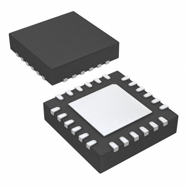
- Part No.:
- A6282EESTR-T
- Manufacturer:
- Allegro MicroSystems
- Category:
- LED Drivers
- Package:
- 24-WFQFN Exposed Pad
- Datasheet:
-
 A6282EESTR-T.pdf
- Description:
- IC LED DRIVER LINEAR 50MA 24QFN
- Quantity:
- Payment:

- Shipping:

Inventory:2,388
Please send an inquiry. Send us your inquiry, and we will respond immediately.
Product details
Overview
A6282EESTR-T from Allegro MicroSystems is a 16-channel constant-current LED sink driver in a 4 mm × 4 mm QFN-24 package with exposed thermal pad, supporting up to 50 mA per channel, 12 V LED load voltage, and 30 MHz serial data input rate for high-speed LED display control.
For engineers reviewing the A6282EESTR-T datasheet, A6282EESTR-T pinout, A6282EESTR-T application, or A6282EESTR-T equivalent, key selection criteria include output current accuracy (±3% between channels), Schmitt-trigger noise immunity, Power-On Reset behavior, thermal shutdown at 165°C, and cascading capability via SDO/SDI.
Technical Context
The A6282EESTR-T integrates a CMOS serial-to-parallel shift register, 16 independent current-regulated sink drivers, and internal UVLO/TSD protection. It operates with logic supply from 3.0–5.5 V and supports LED load voltages up to 12 V while maintaining ±3% output matching across channels.
Control is implemented via four digital inputs: CLK (30 MHz max), LE (level-triggered latch enable), OE (active-low output enable), and SDI/SDO for daisy-chain configuration. Current setting is resistor-programmable via REXT, with internal 1.21 V reference enabling precise per-channel current calculation.
Key Specifications
| Parameter | Value and Actual Design Meaning |
|---|---|
| Output Channels | 16 constant-current sink outputs, each programmable up to 50 mA |
| LED Voltage Support | Up to 12 V VLED - enables driving common LED strings without external boost |
| Logic Supply Range | 3.0–5.5 V - compatible with both 3.3 V and 5 V microcontroller interfaces |
| Max Serial Data Rate | 30 MHz - supports high-refresh-rate displays and fast frame updates |
| Current Matching | ±3% between channels - ensures uniform brightness across multi-LED arrays |
| Thermal Protection | 165°C junction shutdown with 15°C hysteresis - prevents damage during overloads or poor heatsinking |
| Input Hysteresis | 250–900 mV Schmitt trigger - rejects noise on CLK, LE, OE, and SDI lines in noisy environments |
Pinout & Package
Package: 4 mm × 4 mm QFN-24 with exposed thermal pad (ES package), lead-free, 100% matte tin plating. Thermal pad must be connected to GND for optimal power dissipation (RθJA = 37°C/W on 4-layer JEDEC board).
| Pin/Terminal | Circuit Role | Design Meaning |
|---|---|---|
| CLK (Pin 6) | Clock input | Rising-edge-triggered serial data shift clock; supports up to 30 MHz operation |
| LE (Pin 7) | Latch Enable | Level-sensitive control: high transfers shift register contents to output latches |
| OE (Pin 24) | Output Enable | Active-low global enable: high forces all 16 outputs off regardless of latch state |
| SDI (Pin 5) | Serial Data In | CMOS input accepting 3.3/5 V logic; synchronized to CLK rising edge |
| SDO (Pin 1) | Serial Data Out | Open-drain-compatible output enabling daisy-chaining of multiple A6282 devices |
| REXT (Pin 2) | Reference current terminal | Connects external resistor to GND to set all 16 output currents via internal 1.21 V bandgap |
| OUT0–OUT15 (Pins 8–23) | Constant-current sinks | 16 individually controlled current sources; each capable of sinking up to 50 mA |
| VDD (Pin 3) | Logic supply | 3.0–5.5 V CMOS core supply; powers shift register, latches, and control logic |
| GND (Pin 4) | Ground | Common reference for logic, load, and REXT; requires star grounding for optimal current accuracy |
| PAD (Exposed) | Thermal pad | Not electrically connected internally; must be soldered to GND plane with thermal vias for heat removal |
Key Features
| Feature | Design Value |
|---|---|
| Resistor-programmable current | Single REXT sets all 16 outputs; enables precise brightness tuning without trimming or calibration |
| Daisy-chain capability | SDO/SDI interface allows unlimited expansion of LED drive lines without additional MCU GPIOs |
| Power-On Reset (POR) | Guarantees all shift registers and latches initialize to zero - prevents spurious LED activation at startup |
| Integrated protection | UVLO disables outputs below 2.3–2.9 V VDD; thermal shutdown activates at 165°C with automatic recovery |
| Noise-immune inputs | Schmitt-trigger inputs provide ≥250 mV hysteresis - essential for reliable operation in industrial EMI environments |
Applications
| Monocolor LED Signboard | Full-Color LED Display |
|---|---|
Use Scenario: Outdoor alphanumeric signage using discrete red, green, and yellow LEDs arranged in matrix format. IC Role / Device Role / Timing Role: Constant-current sink driver controlling individual LED segments; receives serialized pixel data from MCU and latches column/row states. Use Value: ±3% channel matching ensures consistent segment brightness; 30 MHz data rate supports rapid scrolling and animation without flicker. | Use Scenario: Indoor full-color video wall composed of RGB LED modules with 16×N pixel density per driver IC. IC Role / Device Role / Timing Role: Per-module current sink for one color channel (e.g., red subpixels); cascaded across rows to reduce controller I/O count. Use Value: Resistor-programmable current enables per-module brightness calibration; thermal shutdown protects against localized overheating in dense layouts. |
| Display Backlighting | Multicolor LED Lighting |
Use Scenario: Edge-lit LCD backlight using white LEDs driven in series-parallel strings with local dimming zones. IC Role / Device Role / Timing Role: Zone-level current regulator receiving PWM-modulated serial commands to adjust luminance dynamically. Use Value: 12 V VLED support allows direct connection to standard 12 V rail; low 1.21 V REXT reference minimizes layout sensitivity to ground bounce. | Use Scenario: Architectural accent lighting with tunable white or RGBW fixtures requiring synchronized intensity control. IC Role / Device Role / Timing Role: Channel-specific current sink for warm/cool white or primary color LEDs; configured via daisy-chained serial bus. Use Value: ±7% inter-device current accuracy enables consistent color mixing across multiple A6282EESTR-T units in same fixture. |
Equivalent & Alternatives
The following parts are listed as comparable options for similar constant-current LED driver applications.
| Alternative Part | Technical Difference | Application Difference | Selection Advice |
|---|---|---|---|
| TLC59283DBQR | 16-channel sink driver with 12-bit PWM dimming; no internal UVLO/TSD; max 45 mA/channel | Requires external PWM timing; lacks thermal protection and POR; better for precision dimming over raw current control | Select when fine-grained grayscale control is prioritized over robustness and simplicity |
| STP16DP05PTR | 16-channel sink with 30 MHz SPI interface; integrated error detection; 100 mA max per channel | Higher current capacity but wider TSSOP-24 package; no REXT-based current programming | Choose for higher drive strength and fault reporting in space-tolerant designs |
Compared with TLC59283DBQR and STP16DP05PTR, the A6282EESTR-T offers simpler resistor-based current setting, built-in thermal safety, and guaranteed POR initialization - making it ideal for cost-sensitive, reliability-critical LED signage where deterministic startup and thermal resilience are required.
Availability
A6282EESTR-T is available at Aetrix Electronics and suitable for LED signboard control, full-color display modules, and display backlighting requiring stable component supply, long-term lifecycle support, and RoHS-compliant packaging.
Supply support for A6282EESTR-T includes scheduled delivery planning, volume procurement assistance, BOM continuity management, traceable sourcing, and lifecycle availability coordination for OEM customers, industrial embedded developers, connected-device designers, and electronics production programs.
Manufacturer
Allegro MicroSystems is a U.S.-based designer of high-performance magnetic sensors and power ICs, founded in 1989 and headquartered in Worcester, Massachusetts.
The A6282 product line delivers robust, thermally protected constant-current LED drivers optimized for outdoor signage, commercial displays, and industrial lighting systems demanding reliability under wide temperature and EMI conditions.
FAQ
What is the maximum output current per channel for the A6282EESTR-T?
The A6282EESTR-T supports up to 50 mA per channel when configured with REXT = 374 Ω and VDD = 4.5–5.5 V. Output current is resistor-programmable using the formula IO(max) = (18841.2 / REXT) + 0.68, with minimum REXT = 374 Ω. At REXT = 910 Ω, typical current drops to 21.4 mA per channel.
Does the A6282EESTR-T require an external clock source?
Yes, the A6282EESTR-T requires an external clock signal applied to the CLK pin (Pin 6). It accepts CMOS-level clock inputs up to 30 MHz and uses the rising edge to shift serial data into its internal 16-bit shift register. No internal oscillator is present - timing is fully controlled by the host system.
How does the Power-On Reset (POR) function in the A6282EESTR-T?
The A6282EESTR-T incorporates hardware POR that initializes all internal shift register and latch bits to logic 0 upon power-up. This ensures no unintended LED activation during startup. POR triggers when VDD rises above the UVLO threshold (~2.5–2.7 V), and the device enters normal operation only after stabilization.
Can multiple A6282EESTR-T devices be cascaded, and how is this implemented?
Yes, the A6282EESTR-T supports daisy-chaining via dedicated SDO (Pin 1) and SDI (Pin 5) pins. Serial data flows from SDO of one device to SDI of the next. The CLK and LE signals are shared across all devices in the chain, allowing a single MCU to control dozens of outputs with minimal GPIO usage.
What is the role of the exposed thermal pad on the A6282EESTR-T QFN package?
The exposed thermal pad on the A6282EESTR-T (ES package) is not electrically connected internally but must be soldered to a GND plane with thermal vias. It reduces junction-to-ambient thermal resistance to 37°C/W (on 4-layer JEDEC board), enabling safe operation at full 16-channel load in ambient temperatures up to 85°C.
A6282EESTR-T Specifications
- Product attributes
- Attribute value
- Manufacturer:
- Allegro MicroSystems
- Series:
- -
- Package/Case:
- 24-WFQFN Exposed Pad
- Packaging:
- Tape & Reel (TR)
- Product Status:
- Obsolete
- Type:
- Linear
- Topology:
- Shift Register
- Internal Switch(s):
- Yes
- Number of Outputs:
- 16
- Voltage - Supply (Min):
- 3V
- Voltage - Supply (Max):
- 5.5V
- Voltage - Output:
- 12V
- Current - Output / Channel:
- 50mA
- Frequency:
- 30MHz
- Dimming:
- -
- Applications:
- Backlight
- Operating Temperature:
- -40°C ~ 85°C (TA)
- Grade:
- -
- Qualification:
- -
- Mounting Type:
- Surface Mount
- Supplier Device Package:
- 24-QFN (4x4)
A6282EESTR-T FAQ
1.How can I place an order for A6282EESTR-T through Aetrix?
Please submit a Request for Quotation (RFQ) for A6282EESTR-T on Aetrix. Our sales agent will provide a competitive quotation and guide you through the order confirmation once you accept the terms.
2.Are the price and stock information for A6282EESTR-T reliable?
The price and inventory of A6282EESTR-T are updated periodically and may fluctuate due to market conditions. Stock and pricing data are typically refreshed every 24 hours. Quotation validity for A6282EESTR-T is usually 5 days.
3.What payment methods are accepted for A6282EESTR-T?
We accept Wire Transfer, PayPal, Credit Card, Western Union, MoneyGram, and Escrow for A6282EESTR-T transactions.
Note: Certain payment methods may incur a processing fee.
4.How is shipping managed for A6282EESTR-T?
A6282EESTR-T orders can be shipped via leading logistics carriers, including DHL, UPS, FedEx, TNT, or Registered Mail.
Once your A6282EESTR-T order is processed, you will receive an email with the shipment details and tracking number.
Note: Tracking information may take up to 24 hours to appear. Express delivery typically takes 3–5 business days.
5.How can I obtain technical support or documentation for A6282EESTR-T?
For technical support, including A6282EESTR-T datasheets, pinout diagrams, or application guidance, please contact our engineering support team. They can provide detailed documentation and assistance for your A6282EESTR-T requirements.
6.How does Aetrix verify that A6282EESTR-T is sourced from the original manufacturer or authorized distributors?
All A6282EESTR-T products on Aetrix are procured from qualified distributors and authorized channels. Our dedicated quality assurance team conducts strict verification, including traceability checks and, if necessary, third-party testing. This ensures that A6282EESTR-T meets industry standards.
7.What is the process for return or replacement of A6282EESTR-T?
All A6282EESTR-T units undergo pre-shipment inspection (PSI). If there is an issue with A6282EESTR-T, returns or replacements are accepted under the following conditions:
1.Quantity discrepancies, incorrect items, or visible external defects (such as breakage or corrosion), acknowledged by Aetrix.
2.The issue is reported within 90 days of delivery.
3.The A6282EESTR-T part is unused and in its original packaging.
Return procedure for A6282EESTR-T:
1.Submit a request within 90 days.
2.Obtain a Return Material Authorization (RMA) from Aetrix.
A6282EESTR-T Tags

-
BCR402RE6327HTSA1
Infineon Technologies

-
BCR430UXTSA2
Infineon Technologies

-
BCR420UE6433HTMA1
Infineon Technologies
-
BCR420UE6327HTSA1
Infineon Technologies
-
BCR421UE6327HTSA1
Infineon Technologies

-
LYT1604D-TL
Power Integrations

-
HV9910CLG-G
Microchip Technology

-
CL2N8-G
Microchip Technology

-
BCR420UW6-7
Diodes Incorporated
-
BCR421UW6-7
Diodes Incorporated

-
BCR420UFD-7
Diodes Incorporated
-
BCR421UFD-7
Diodes Incorporated
Tech Hub

A practical engineering and sourcing framework covering lifecycle verification, lifetime-buy calculations, replacement qualification, supplier checks and counterfeit-risk controls.

TTL and CMOS logic families differ in thresholds, loading, output drive, power and timing. This engineering guide compares 74HC and 74HCT, calculates noise margins and checks 3.3 V/5 V compatibility.

A practical engineering guide to 3.3V and 5V logic compatibility, input thresholds, resistor dividers, translator ICs, MOSFET level shifting, I2C pull-ups, timing limits and power-sequencing risks.

The 74HC595 uses push-pull logic outputs, while the TPIC6B595 uses 50 V open-drain DMOS sinks for higher-power loads. This guide compares timing, current limits, 3.3 V interfacing, load wiring, thermal…

The 74HC595 converts serial data into eight stable parallel outputs. This guide covers pin functions, shift and storage timing, OE and MR behavior, drive-current limits, cascading, voltage compatibilit…

A technical comparison of level-sensitive latches and edge-triggered flip-flops, covering timing windows, setup and hold limits, master–slave operation, time borrowing, race-through, HDL inference and…

A D latch stores one bit while Enable controls when data can pass. This reference covers gate-level operation, truth tables, transparency, setup and hold timing, LE versus OE, common ICs and practical …

An SR latch stores one bit through cross-coupled feedback. This engineering reference covers NOR and NAND implementations, truth tables, forbidden-state recovery, gated operation, switch debouncing, fa…

Latch circuits retain one bit through feedback. This technical reference covers SR and D latches, truth tables, transparency, timing limits, latch-versus-flip-flop behavior, applications and common log…

An engineering guide to LED driver operation, constant-current and constant-voltage outputs, linear and switching topologies, dimming, IC selection, calculations, replacement compatibility, and fault c…


