
 My Inquiry
 My Account


Allegro MicroSystems A8282SLBTR
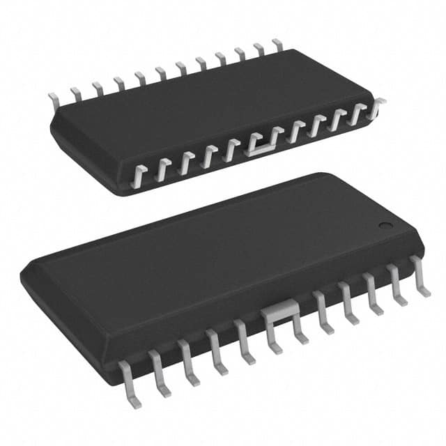
- Part No.:
- A8282SLBTR
- Manufacturer:
- Allegro MicroSystems
- Category:
- Special Purpose Regulators
- Package:
- 24-SOIC (0.295", 7.50mm Width)
- Datasheet:
-
 A8282SLBTR.pdf
- Description:
- IC REG CONV RECVRS 1OUT 24SOIC
- Quantity:
- Payment:

- Shipping:

Inventory:3,820
Please send an inquiry. Send us your inquiry, and we will respond immediately.
Product details
Overview
A8282SLBTR from Allegro MicroSystems is a monolithic LNB supply and control-voltage regulator IC designed for satellite receiver systems. It delivers programmable 12–21 V output to low-noise block downconverters (LNBs) via coaxial cable, integrates a factory-trimmed 22-kHz tone oscillator for DiSEqC™ encoding, and features cable-length compensation (LLC), reverse-current protection, and thermal shutdown. Used in analog/digital satellite receivers requiring stable, low-noise DC power over long coax runs.
For engineers reviewing the A8282SLBTR datasheet, A8282SLBTR pinout, A8282SLBTR application, or A8282SLBTR equivalent, this page provides verified technical context, real-world design meaning of key specs, validated pin functions, confirmed alternatives with functional distinctions, and supply-chain support details specific to satellite LNB power management.
Technical Context
The A8282SLBTR combines a current-mode buck converter (352 kHz switching frequency, 16× tone frequency) with a tracking linear regulator to minimize power dissipation across its 12–21 V output range. The buck stage supplies the linear regulator with VBULK voltage dynamically adjusted to maintain ~900 mV headroom above VLNB, enabling efficient tone injection and load regulation.
It supports four discrete output voltages (12/13/18/20 V) via dual VSEL logic inputs and adds ±1 V cable-drop compensation via LLC input. Internal short-circuit protection uses an external sense resistor (RS) referenced to a 135 mV threshold, while OLF provides open-drain fault signaling for overload or thermal shutdown events.
Key Specifications
| Parameter | Value and Actual Design Meaning |
|---|---|
| Output Voltage Range | 12–21 V selectable in 4 discrete steps; enables compatibility with global LNB standards including DirecTV® 13.44 V mode. |
| Switching Frequency | 352 kHz nominal; synchronized to 22-kHz tone for clean DiSEqC™ signal integrity and reduced EMI coupling. |
| Buck Switch RDS(on) | 0.57 Ω typical at 25°C; determines conduction loss and thermal rise under 750 mA load. |
| Tone Frequency Accuracy | 20–24 kHz (typ. 22 kHz); factory-trimmed for compliance with EUTELSAT DiSEqC™ coax bus timing requirements. |
| Thermal Shutdown Threshold | 165°C junction temperature; triggers OLF flag and disables output to prevent damage during sustained overload or poor heatsinking. |
| Reverse Current Limit | 1–5 mA max when EN = L and VLNB = 22 V; allows safe sharing of coaxial cable among multiple satellite receivers in standby. |
| Supply Voltage Range | 4.5 V + VLNB to 47 V; accommodates wide input variations common in outdoor satellite power distribution. |
Pinout & Package
Package: 24-pin SOICW (wide-body), Pb-free matte tin leadframe plating, internally fused ground leads (pins 6, 7, 18, 19) for enhanced thermal dissipation (RθJA = 35°C/W on JEDEC high-K board).
| Pin/Terminal | Circuit Role | Design Meaning |
|---|---|---|
| 1 (EXTM) | External modulation input | AC-coupled 100–125 mVPP 22-kHz signal path; enables DiSEqC™-compliant remote LNB control without internal tone generator. |
| 2 (OLF) | Overload flag output | Open-drain diagnostic output pulled low during short-circuit or thermal fault; requires external pull-up for microcontroller monitoring. |
| 3 (VBULK) | Buck-regulator output | Tracking supply for linear stage; voltage = VLNB + ~900 mV; sets headroom for tone injection and minimizes linear-stage dissipation. |
| 8 (SENSE) | Current-limit sense input | Connects to RS resistor; internal 135 mV reference sets ILNBM = 0.135 V / RS; enables precise 500–750 mA short-circuit thresholds. |
| 9 (LNB) | LNB output terminal | Main regulated DC output (12–21 V); drives coaxial cable and LNB; supports 22-kHz tone superposition and DiSEqC™ burst coding. |
| 10 (LX) | Buck switch node | Drives external inductor (100 µH); fast-switching node requiring Schottky clamp diode (D1) and careful PCB layout to limit EMI. |
| 11 (VIN) | Main supply input | Accepts 4.5 V + VLNB to 47 V; must be decoupled with low-ESR electrolytic capacitor near pin to handle high ripple current. |
| 12 (TCAP) | Slew-rate control | RC network (25 kΩ internal + external C) sets VLNB rise/fall time; 4.7–47 nF range balances cable compensation vs. overshoot risk. |
| 13 (LLC) | Cable-length compensation enable | Logic-high adds +1 V to selected VLNB; compensates for coaxial voltage drop up to ~100 m, critical for large dish installations. |
| 14 (VSEL1), 15 (VSEL0) | Voltage select inputs | Binary-coded logic inputs selecting 12/13/18/20 V output; H/L states define exact LNB bias per EUTELSAT and regional standards. |
| 16 (EN) | Enable input | Active-high logic control; disables LNB output and reduces quiescent current to 0.25–1 mA in standby, enabling multi-receiver coax sharing. |
| 17 (ENT) | Tone enable input | Activates internal 22-kHz trapezoidal tone generator; fast response enables DiSEqC™ 1.x burst coding without external oscillator. |
| 20 (CPUMP), 21 (VPUMP), 22 (PUMPX) | Charge-pump circuit | Generates gate drive for high-side buck switch; requires external CPUMP capacitor (0.1 µF ceramic) for stable VPUMP regulation. |
| 23 (VINT) | Internal reference bypass | Requires 1–10 µF tantalum or ceramic capacitor; stabilizes internal 5 V reference used by VSEL/LLC logic and TCAP timing network. |
| 6, 7, 18, 19 (GND) | Ground terminals | Fused internal ground leads; must connect to heavy copper ground plane using multiple vias to ensure thermal performance and noise immunity. |
Key Features
| Feature | Design Value |
|---|---|
| Cable-length compensation (LLC) | Enables +1 V boost to selected output voltage, directly offsetting coaxial voltage drop-critical for reliable LNB operation beyond 50 m cable runs. |
| Factory-trimmed 22-kHz tone oscillator | Eliminates external crystal or RC timing components; ensures DiSEqC™-compliant frequency accuracy (±10%) without calibration or trimming. |
| Tracking buck-linear architecture | Maintains ~900 mV headroom above VLNB, reducing linear-stage power dissipation by >60% compared to fixed-headroom designs at 18 V output. |
| Externally adjustable short-circuit protection | RS resistor sets precise current limit (e.g., 140 mΩ → 750 mA); avoids overdesign of external components while meeting IEC/ETSI LNB safety requirements. |
| Reverse-current protection in standby | Limits backfeed to ≤5 mA when EN = L, allowing multiple receivers to share one coaxial line without cross-interference or power conflict. |
Applications
| Digital Satellite Receiver | Multi-LNB Switching System |
|---|---|
Use Scenario: Consumer-grade set-top box powering single universal LNB for Ku-band reception. IC Role / Device Role / Timing Role: Primary LNB supply regulator delivering 13/18 V DC and 22-kHz tone for polarization selection and DiSEqC™ channel switching. Use Value: Factory-trimmed tone and integrated protection eliminate external timing components and reduce BOM count by 3–5 parts versus discrete solutions. |
Use Scenario: Commercial multiswitch unit distributing signals from 4–16 LNBs to multiple receivers over shared coax infrastructure. IC Role / Device Role / Timing Role: Individual LNB power controller with EN/OLF coordination enabling dynamic LNB activation and fault isolation per port. Use Value: Reverse-current limiting and precise 12–21 V selection allow safe hot-plug operation and compatibility with legacy and modern LNBs on same coax trunk. |
| DirecTV®-Compliant Terminal | Professional Satellite Installation Kit |
Use Scenario: North American direct broadcast receiver requiring 13.44 V LNB bias per DirecTV specification. IC Role / Device Role / Timing Role: Voltage-boosted LNB regulator using VINT–TCAP resistor network to raise nominal 13 V output by 440 mV. Use Value: Eliminates need for custom voltage-divider feedback networks; achieves compliant bias with single 1-MΩ resistor and standard A8282SLBTR configuration. |
Use Scenario: Field-deployable test instrument verifying LNB functionality, tone presence, and DiSEqC™ response in commercial installations. IC Role / Device Role / Timing Role: Programmable LNB power source with real-time voltage selection (VSEL0/VSEL1), tone enable (ENT), and fault monitoring (OLF). Use Value: On-the-fly voltage and tone control via logic inputs enables rapid validation of all LNB modes without hardware reconfiguration or external signal generators. |
Equivalent & Alternatives
The following parts are listed as comparable options for similar LNB supply and control-voltage regulator applications.
| Alternative Part | Technical Difference | Application Difference | Selection Advice |
|---|---|---|---|
| MAX22026ATJ+T | Single 13/18-V output; no VSEL0/VSEL1 binary selection; lacks LLC compensation and VINT reference pin. | Supports basic DiSEqC™ but not DirecTV® 13.44 V mode or long-cable installations requiring voltage boost. | Choose for cost-sensitive single-LNB designs where cable length ≤30 m and regional voltage variants are fixed. |
| STV1282A | Integrated 22-kHz oscillator; 13/18-V only; no external modulation (EXTM) or slew-rate control (TCAP) pins. | Valid for legacy analog satellite receivers but lacks DiSEqC™ burst coding speed and diagnostics (OLF) required for modern digital protocols. | Choose for retrofit projects using older STMicroelectronics platform designs; verify OLF absence does not impact system fault reporting. |
Compared with MAX22026ATJ+T and STV1282A, the A8282SLBTR provides broader voltage flexibility (12–21 V), active cable compensation (LLC), and comprehensive diagnostics (OLF), making it suitable for next-generation multi-standard satellite receivers requiring field-programmable LNB bias and robust fault handling.
Availability
A8282SLBTR is available at Aetrix Electronics and suitable for digital satellite receivers, multi-LNB switching systems, and DirecTV®-compliant terminals requiring stable component supply, long-term lifecycle support, and traceable sourcing for broadcast equipment manufacturing.
Supply support for A8282SLBTR includes scheduled delivery planning, volume procurement assistance, BOM continuity management, traceable sourcing, and lifecycle availability coordination for OEM customers, industrial embedded developers, connected-device designers, and electronics production programs.
Manufacturer
Allegro MicroSystems is a U.S.-based designer and manufacturer of high-performance magnetic sensing and power ICs, serving automotive, industrial, and communications markets since 1989.
The A8282SLBTR belongs to Allegro's LNB supply and control-voltage regulator product line, engineered specifically for satellite receiver power management with integrated DiSEqC™ tone generation, cable-drop compensation, and thermal-safe operation.
FAQ
What output voltages does the A8282SLBTR support, and how are they selected?
The A8282SLBTR supports four discrete output voltages: 12 V, 13 V, 18 V, and 20 V, selected via the logic states of VSEL0 and VSEL1 pins. An additional +1 V boost is enabled by asserting the LLC pin high, yielding 14 V, 19 V, 21 V, or 13 V depending on base selection. This binary-select + compensation scheme meets regional LNB standards including EUTELSAT and DirecTV® specifications without external DACs or resistive dividers.
How does the A8282SLBTR implement DiSEqC™-compliant 22-kHz tone generation?
The A8282SLBTR integrates a factory-trimmed 22-kHz oscillator that produces a trapezoidal waveform with 40–60% duty cycle and 400–900 mVPP amplitude at the LNB output. Activation is controlled by the ENT pin, and the tone is injected directly into the regulated DC output. No external crystal or timing components are needed, and burst coding is supported due to fast ENT response (<10 µs), enabling full DiSEqC™ 1.0/1.1/1.2 protocol implementation.
What is the purpose of the VINT pin on the A8282SLBTR, and what capacitor value is recommended?
The VINT pin on the A8282SLBTR provides access to an internal 5 V reference used by the VSEL/LLC logic comparators and TCAP timing network. It must be bypassed with a 1–10 µF capacitor (tantalum or ceramic) placed adjacent to the pin. This stabilization prevents logic misstates during voltage transients and ensures accurate slew-rate control and voltage selection-omitting or undersizing this capacitor risks erratic VSEL interpretation or unstable TCAP timing.
Can the A8282SLBTR be used in multi-receiver coaxial sharing applications, and how is reverse current limited?
Yes-the A8282SLBTR supports multi-receiver coaxial sharing via its EN pin. When EN is driven low, the LNB output is disabled and reverse current is actively limited to 1–5 mA (typ. 1 mA) even if VLNB = 22 V and VIN is floating or at 22 V. This prevents backfeeding between receivers on the same coax line, eliminating cross-talk and ensuring safe hot-plug operation without external blocking diodes or complex sequencing.
What thermal performance can be expected from the A8282SLBTR in a standard PCB layout?
On a JEDEC-compliant "high-K" four-layer board, the A8282SLBTR exhibits a junction-to-ambient thermal resistance (RθJA) of 35°C/W. With a 750 mA load at 18 V output and 24 V input, total power dissipation is ~1.8 W; this yields a junction temperature rise of ~63°C above ambient. Using the fused ground leads (pins 6, 7, 18, 19) with ≥3 in² copper per side reduces thermal impedance further, enabling reliable operation up to +85°C ambient without forced air cooling.
A8282SLBTR Specifications
- Product attributes
- Attribute value
- Manufacturer:
- Allegro MicroSystems
- Series:
- -
- Package/Case:
- 24-SOIC (0.295", 7.50mm Width)
- Packaging:
- Tape & Reel (TR)
- Product Status:
- Obsolete
- Applications:
- Converter, Analog and Digital Satellite Receivers
- Voltage - Input:
- 16.5V ~ 48V
- Number of Outputs:
- 1
- Voltage - Output:
- 12V ~ 20V
- Operating Temperature:
- -20°C ~ 85°C
- Grade:
- -
- Qualification:
- -
- Mounting Type:
- Surface Mount
- Supplier Device Package:
- 24-SOIC
A8282SLBTR FAQ
1.How can I place an order for A8282SLBTR through Aetrix?
Please submit a Request for Quotation (RFQ) for A8282SLBTR on Aetrix. Our sales agent will provide a competitive quotation and guide you through the order confirmation once you accept the terms.
2.Are the price and stock information for A8282SLBTR reliable?
The price and inventory of A8282SLBTR are updated periodically and may fluctuate due to market conditions. Stock and pricing data are typically refreshed every 24 hours. Quotation validity for A8282SLBTR is usually 5 days.
3.What payment methods are accepted for A8282SLBTR?
We accept Wire Transfer, PayPal, Credit Card, Western Union, MoneyGram, and Escrow for A8282SLBTR transactions.
Note: Certain payment methods may incur a processing fee.
4.How is shipping managed for A8282SLBTR?
A8282SLBTR orders can be shipped via leading logistics carriers, including DHL, UPS, FedEx, TNT, or Registered Mail.
Once your A8282SLBTR order is processed, you will receive an email with the shipment details and tracking number.
Note: Tracking information may take up to 24 hours to appear. Express delivery typically takes 3–5 business days.
5.How can I obtain technical support or documentation for A8282SLBTR?
For technical support, including A8282SLBTR datasheets, pinout diagrams, or application guidance, please contact our engineering support team. They can provide detailed documentation and assistance for your A8282SLBTR requirements.
6.How does Aetrix verify that A8282SLBTR is sourced from the original manufacturer or authorized distributors?
All A8282SLBTR products on Aetrix are procured from qualified distributors and authorized channels. Our dedicated quality assurance team conducts strict verification, including traceability checks and, if necessary, third-party testing. This ensures that A8282SLBTR meets industry standards.
7.What is the process for return or replacement of A8282SLBTR?
All A8282SLBTR units undergo pre-shipment inspection (PSI). If there is an issue with A8282SLBTR, returns or replacements are accepted under the following conditions:
1.Quantity discrepancies, incorrect items, or visible external defects (such as breakage or corrosion), acknowledged by Aetrix.
2.The issue is reported within 90 days of delivery.
3.The A8282SLBTR part is unused and in its original packaging.
Return procedure for A8282SLBTR:
1.Submit a request within 90 days.
2.Obtain a Return Material Authorization (RMA) from Aetrix.
A8282SLBTR Tags

-
TPS51206DSQR
Texas Instruments

-
TPS51200DRCR
Texas Instruments
-
TPS51200DRCT
Texas Instruments

-
TPS62740DSSR
Texas Instruments

-
TPS51100DGQR
Texas Instruments

-
NCP51200MNTXG
onsemi
-
NCP51400MNTXG
onsemi

-
RT9026GSP
Richtek USA Inc.

-
LP2998MRX/NOPB
Texas Instruments
-
TPS51200QDRCRQ1
Texas Instruments

-
DPA423GN-TL
Power Integrations
-
LM10011SD/NOPB
Texas Instruments
Tech Hub

A practical engineering and sourcing framework covering lifecycle verification, lifetime-buy calculations, replacement qualification, supplier checks and counterfeit-risk controls.

TTL and CMOS logic families differ in thresholds, loading, output drive, power and timing. This engineering guide compares 74HC and 74HCT, calculates noise margins and checks 3.3 V/5 V compatibility.

A practical engineering guide to 3.3V and 5V logic compatibility, input thresholds, resistor dividers, translator ICs, MOSFET level shifting, I2C pull-ups, timing limits and power-sequencing risks.

The 74HC595 uses push-pull logic outputs, while the TPIC6B595 uses 50 V open-drain DMOS sinks for higher-power loads. This guide compares timing, current limits, 3.3 V interfacing, load wiring, thermal…

The 74HC595 converts serial data into eight stable parallel outputs. This guide covers pin functions, shift and storage timing, OE and MR behavior, drive-current limits, cascading, voltage compatibilit…

A technical comparison of level-sensitive latches and edge-triggered flip-flops, covering timing windows, setup and hold limits, master–slave operation, time borrowing, race-through, HDL inference and…

A D latch stores one bit while Enable controls when data can pass. This reference covers gate-level operation, truth tables, transparency, setup and hold timing, LE versus OE, common ICs and practical …

An SR latch stores one bit through cross-coupled feedback. This engineering reference covers NOR and NAND implementations, truth tables, forbidden-state recovery, gated operation, switch debouncing, fa…

Latch circuits retain one bit through feedback. This technical reference covers SR and D latches, truth tables, transparency, timing limits, latch-versus-flip-flop behavior, applications and common log…

An engineering guide to LED driver operation, constant-current and constant-voltage outputs, linear and switching topologies, dimming, IC selection, calculations, replacement compatibility, and fault c…


