
 My Inquiry
 My Account


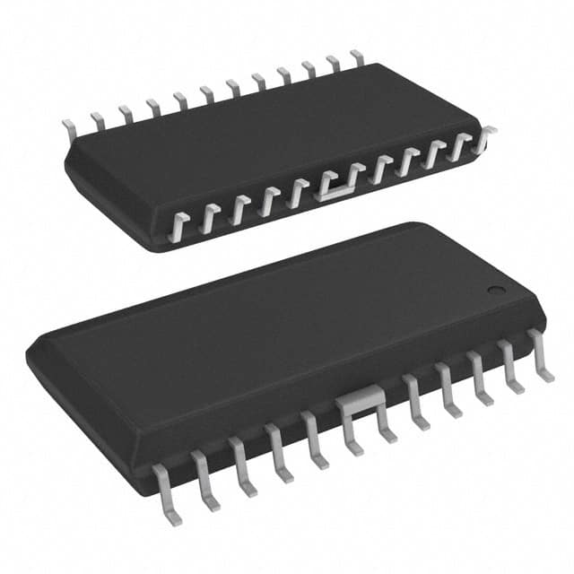
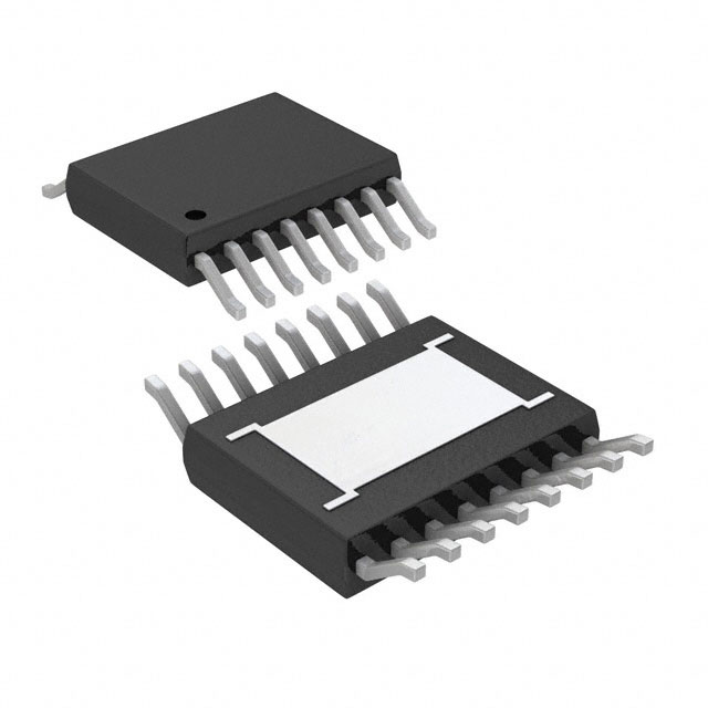
Allegro MicroSystems A8450KLB
- Part No.:
- A8450KLB
- Manufacturer:
- Allegro MicroSystems
- Category:
- Voltage Regulators - Linear + Switching
- Package:
- 24-SOIC (0.295", 7.50mm Width)
- Datasheet:
-
 A8450KLB.pdf
- Description:
- IC REG QUAD BUCK/LINEAR 24SOIC
- Quantity:
- Payment:

- Shipping:

Inventory:3,845
Please send an inquiry. Send us your inquiry, and we will respond immediately.
Product details
Overview
A8450KLB from Allegro MicroSystems is an automotive-grade multi-output power management IC integrating a 5.7 V buck converter, dual 5 V linear regulators (digital and analog), a fixed 3.3 V LDO, and an adjustable 1.2–3.3 V LDO - all operating from 6–45 V input and rated for –40°C to +135°C ambient. It delivers up to 550 mA total regulated output current and supports engine ignition enable via ENBAT pin.
For engineers reviewing the A8450KLB datasheet, A8450KLB pinout, A8450KLB application, or A8450KLB equivalent, key selection criteria include its dual 5 V tracking (< 0.5%), short-to-battery protection on V5A, foldback current limiting across all regulators, thermal shutdown at 175°C, and SOIC-W-24 package with fused ground pins for enhanced thermal performance.
Technical Context
The A8450KLB implements a current-mode variable-frequency buck converter with soft-start, 415 mΩ typical RDS(on) at 25°C, and 1.2 A typical current limit. Its charge pump (CP1/CP2/VCP) enables N-channel MOSFET gate drive and supports 100% duty cycle operation below 12 V input.
Four independent linear regulators are controlled by internal references and feedback loops: V5D and V5A track within ±25 mV over temperature; V33 is fixed at 3.300 V ±2%; VADJ is set externally via FB pin (1.20 V reference) and resistor divider. All regulators feature foldback current limiting triggered at 175–225 mV across CLx pins.
Key Specifications
| Parameter | Value and Actual Design Meaning |
|---|---|
| Input Voltage Range | 6 V to 45 V - supports wide automotive battery transients including cold-crank and load-dump conditions. |
| Buck Output Voltage | 5.7 V typical - supplies VREG rail that powers all linear regulators and internal circuitry. |
| V5D / V5A Output | 5.0 V ±2%, 200 mA each - digitally isolated outputs with < 0.5% tracking ensures precise ADC reference and digital logic supply matching. |
| V33 Output | 3.300 V ±2%, 3.234–3.366 V - stable core/I/O supply for microcontrollers with 80 mV hysteresis UVLO. |
| VADJ Range | 1.2 V to 3.3 V - externally adjustable via FB pin (1.20 V reference) and resistor divider for flexible core voltage scaling. |
| Quiescent Current | <10 µA in disabled mode - enables ultra-low-power sleep state compatible with automotive always-on requirements. |
| Operating Temperature | –40°C to +135°C ambient - qualified for under-hood applications with junction limit of 150°C and thermal shutdown at 175°C. |
Pinout & Package
Package: 24-pin SOIC-W surface-mount (suffix LB), with internally fused power ground pins (pins 6–7 and 18–19) providing enhanced thermal performance (RθJA = 35°C/W on 4-layer board).
| Pin/Terminal | Circuit Role | Design Meaning |
|---|---|---|
| LX | Buck switch node | Connects to external inductor and Schottky catch diode; carries high-frequency switching current. |
| ENBAT | High-voltage enable input | Accepts 2.7–45 V ignition/battery-switch signal; enables wake-up without level-shifting circuitry. |
| V33 | Fixed 3.3 V LDO output | Supplies MCU I/O, sensors, or low-power peripherals; includes foldback current limiting via CL33 pin. |
| V33BD | 3.3 V base drive output | Drives external npn pass transistor Q1; delivers up to 10 mA base current for stable regulation. |
| CL33 | 3.3 V current limit sense | Sets foldback threshold (175–225 mV) for V33 regulator; connects to current-sense resistor R3. |
| GND | Power ground (pins 6–7, 18–19) | Fused internal ground connections reduce thermal resistance and improve current handling capability. |
| VREG | Buck-regulated 5.7 V output | Primary power rail feeding all linear regulators; monitored for UVLO (4.94–5.36 V threshold). |
| V5D | Digital 5 V LDO output | Supplies digital logic; tracks V5A within ±25 mV; protected by foldback current limit (200–300 mA). |
| NFAULT | Open-drain fault indicator | Pulled low on V5A short-to-battery, V5A/V5D UVLO, or thermal warning (>160°C junction). |
| NPOR | Open-drain power-on-reset | Asserted low during V33/VADJ UVLO, VREG UVLO, or simultaneous ENB/ENBAT low; delay set by C9 on CPOR. |
| V5A | Analog 5 V LDO output | Supplies precision analog circuits and ADC references; includes short-to-supply protection and tracking control. |
| VBB | Main input supply | Accepts 6–45 V automotive battery input; absolute max rating is –40 V (reverse polarity tolerant). |
| CP2 / CP1 / VCP | Charge pump terminals | Generate gate-drive voltage above VBB for internal N-MOSFET; require 0.1 µF ceramic caps (C7/C8). |
| VREG11 | VREG monitor output | Provides buffered copy of VREG for external monitoring or sequencing control. |
| ENB | Logic-level enable input | Accepts 2.7–6.5 V microcontroller signal; used for reset initiation or secondary enable control. |
| CPOR | POR capacitor connection | External capacitor (C9) sets POR delay: tPOR = 213 ms/µF (e.g., 0.47 µF → 100 ms typical). |
| CLADJ | Adjustable regulator current limit | Sets foldback threshold for VADJ regulator; connects to current-sense resistor R4. |
| VADJBD | Adjustable regulator base drive | Drives external npn pass transistor Q2; delivers up to 10 mA base current for VADJ regulation. |
| FB | Feedback input | 1.20 V reference point for VADJ; output voltage calculated as VOUT = 1.20 × (1 + R1/R2). |
| VIN | Internal VREG input | Not externally accessible; internal connection point for VREG rail distribution. |
| H.V. | High-voltage detection node | Internal sensing node for ENBAT overvoltage protection and charge pump control. |
| A8450 | Device identifier | Label pin for identification; no electrical function. |
Key Features
| Feature | Design Value |
|---|---|
| Dual 5 V tracking | V5A and V5D maintain ≤0.5% output deviation across –40°C to +135°C, enabling synchronized analog/digital subsystems. |
| Short-to-battery protection | V5A regulator detects and shuts down during V5A-to-VBB shorts - critical for automotive sensor interface safety. |
| Ignition-switch enable | ENBAT pin accepts direct 12/24 V battery or ignition signals without external level shifters or pull-ups. |
| 100% duty cycle operation | Maintains regulation down to 6 V input by extending off-time; prevents dropout during cold-crank events. |
| Thermal warning & shutdown | Open-drain NFAULT asserts at 160°C (warning) and disables buck stage at 175°C (shutdown), with 15°C hysteresis. |
| Adjustable POR delay | Reset timing set externally via C9 on CPOR pin - allows precise synchronization with MCU boot sequence. |
Applications
| Engine Control Unit (ECU) | Advanced Driver Assistance Systems (ADAS) |
|---|---|
Use Scenario: Powering MCU, CAN transceivers, and analog front-ends in gasoline/diesel ECU modules exposed to under-hood temperatures up to 135°C. IC Role / Device Role / Timing Role: Central power manager delivering tightly tracked 5 V analog/digital rails, 3.3 V I/O, and adjustable core voltage while monitoring thermal and supply faults. Use Value: Eliminates need for discrete LDOs and tracking circuits; integrated fault signaling reduces BOM count and improves system-level diagnostics. | Use Scenario: Supplying image sensor interfaces, radar signal processors, and safety-critical microcontrollers in forward-facing camera or radar modules. IC Role / Device Role / Timing Role: Provides low-noise 5 V analog rail for ADC references and matched 5 V digital rail for FPGA/MCU cores, with sub-25 mV tracking error. Use Value: Ensures consistent timing margins between analog sampling and digital processing paths, reducing jitter-induced measurement errors. |
| Body Control Module (BCM) | Infotainment Head Unit |
Use Scenario: Managing power for door lock actuators, lighting drivers, and LIN bus nodes in vehicle body electronics with extended temperature cycling. IC Role / Device Role / Timing Role: Delivers regulated 5 V, 3.3 V, and adjustable voltage rails while supporting low-quiescent sleep mode (<10 µA) during vehicle standby. Use Value: Enables compliance with ISO 16750-2 quiescent current requirements and extends battery life during parking mode. | Use Scenario: Powering application processors, display controllers, and audio codecs in center-stack infotainment systems with high transient load demands. IC Role / Device Role / Timing Role: Supplies stable 3.3 V I/O and 1.2–3.3 V core voltage to SoCs using external npn pass transistors, with programmable current limiting. Use Value: Allows dynamic voltage scaling for power optimization while maintaining safe thermal limits via integrated TSD and fault reporting. |
Equivalent & Alternatives
The following parts are listed as comparable options for similar multi-output automotive voltage regulator applications.
| Alternative Part | Technical Difference | Application Difference | Selection Advice |
|---|---|---|---|
| TPS65381A-Q1 | Triple-output buck-boost + LDO; integrates watchdog timer and SPI interface; no adjustable LDO; 40-V max input. | Requires external sequencing logic for multi-rail startup; lacks V5A short-to-battery protection. | Choose when system-level diagnostics and programmability outweigh need for analog rail protection and adjustable core voltage. |
| MAX25201ATPA/V+ | Dual buck + triple LDO; 4.5–36 V input; includes CAN FD transceiver; no adjustable LDO; 150°C max ambient. | Integrated CAN PHY simplifies communication subsystems but adds fixed-function overhead for non-CAN designs. | Prefer when CAN FD interface is required and thermal margin >135°C is acceptable; not suitable for 45 V load-dump environments. |
Compared with TPS65381A-Q1 and MAX25201ATPA/V+, the A8450KLB uniquely combines dual 5 V tracking with short-to-battery protection on V5A, a true 1.2–3.3 V adjustable LDO, and 45 V input tolerance - making it optimal for high-reliability engine bay and ADAS power domains where analog integrity and fault resilience are critical.
Availability
A8450KLB is available at Aetrix Electronics and suitable for automotive engine control units, ADAS sensor modules, body control modules, and infotainment head units requiring stable component supply across extended temperature and voltage ranges.
Supply support for A8450KLB includes scheduled delivery planning, volume procurement assistance, BOM continuity management, traceable sourcing, and lifecycle availability coordination for OEM customers, industrial embedded developers, connected-device designers, and electronics production programs.
Manufacturer
Allegro MicroSystems is a U.S.-based designer and manufacturer of high-performance magnetic sensing and power IC solutions, specializing in automotive, industrial, and motion-control applications.
The A8450 product line is engineered specifically for automotive power management in harsh environments - delivering multi-rail regulation, fault resilience, and thermal robustness for under-hood and safety-critical electronic control units.
FAQ
What is the maximum input voltage rating for the A8450KLB?
The A8450KLB supports an absolute maximum input voltage of –40 V on the VBB pin, with normal operation specified from 6 V to 45 V. This 45 V rating accommodates automotive load-dump transients per ISO 7637-2, ensuring reliable operation in 24 V commercial vehicle systems. The device remains functional during cold-crank events down to 6 V due to its 100% duty cycle capability.
How does the A8450KLB achieve V5A and V5D output tracking?
The A8450KLB achieves V5A and V5D tracking through an integrated analog tracking control loop that actively matches their reference voltages and error amplifiers. This architecture guarantees ≤0.5% tracking deviation (±25 mV) across –40°C to +135°C ambient and full load range (50–200 mA per rail). The A8450KLB maintains this specification without requiring external components or calibration.
Can the A8450KLB operate in automotive sleep mode with ultra-low quiescent current?
Yes - when both ENBAT and ENB pins are pulled low, the A8450KLB enters disabled mode and draws less than 10 µA from VBB. This ultra-low quiescent current meets stringent automotive ISO 16750-2 requirements for parked vehicle battery drain. The device wakes instantly upon either enable pin going high, with internal charge pump stabilization completing in ≈300 µs before regulation resumes.
What protection features are implemented on the V5A regulator of the A8450KLB?
The V5A regulator in the A8450KLB includes dedicated short-to-battery protection, which detects and disables the output if V5A is shorted to VBB. It also features foldback current limiting (200–300 mA trip), undervoltage lockout (4.36–4.75 V rising threshold), and thermal shutdown coordination via the shared NFAULT pin. These protections are hardware-based and require no configuration.
Is the A8450KLB pinout compatible with other Allegro multi-output regulators?
No - the A8450KLB uses a proprietary 24-pin SOIC-W pinout optimized for its specific regulator topology, charge pump interface, and fault signaling scheme. Pin assignments such as CP1/CP2/VCP, CL33/CLADJ, and VREG11 are unique to the A8450 family. Migration to other Allegro regulators (e.g., A8451) requires PCB redesign due to incompatible pin mapping and functional allocation.
A8450KLB Specifications
- Product attributes
- Attribute value
- Manufacturer:
- Allegro MicroSystems
- Series:
- -
- Package/Case:
- 24-SOIC (0.295", 7.50mm Width)
- Packaging:
- Tube
- Product Status:
- Obsolete
- Topology:
- Step-Down (Buck) (1), Linear (LDO) (4)
- Number of Outputs:
- 4
- Frequency - Switching:
- -
- Voltage/Current - Output 1:
- 3.3V, 200mA
- Voltage/Current - Output 2:
- 1.2V ~ 3.3V, 200mA
- Voltage/Current - Output 3:
- 5V, 200mA
- w/LED Driver:
- No
- w/Supervisor:
- No
- w/Sequencer:
- Yes
- Voltage - Supply:
- 6V ~ 45V
- Operating Temperature:
- -40°C ~ 135°C
- Grade:
- -
- Qualification:
- -
- Mounting Type:
- Surface Mount
- Supplier Device Package:
- 24-SOIC
A8450KLB FAQ
1.How can I place an order for A8450KLB through Aetrix?
Please submit a Request for Quotation (RFQ) for A8450KLB on Aetrix. Our sales agent will provide a competitive quotation and guide you through the order confirmation once you accept the terms.
2.Are the price and stock information for A8450KLB reliable?
The price and inventory of A8450KLB are updated periodically and may fluctuate due to market conditions. Stock and pricing data are typically refreshed every 24 hours. Quotation validity for A8450KLB is usually 5 days.
3.What payment methods are accepted for A8450KLB?
We accept Wire Transfer, PayPal, Credit Card, Western Union, MoneyGram, and Escrow for A8450KLB transactions.
Note: Certain payment methods may incur a processing fee.
4.How is shipping managed for A8450KLB?
A8450KLB orders can be shipped via leading logistics carriers, including DHL, UPS, FedEx, TNT, or Registered Mail.
Once your A8450KLB order is processed, you will receive an email with the shipment details and tracking number.
Note: Tracking information may take up to 24 hours to appear. Express delivery typically takes 3–5 business days.
5.How can I obtain technical support or documentation for A8450KLB?
For technical support, including A8450KLB datasheets, pinout diagrams, or application guidance, please contact our engineering support team. They can provide detailed documentation and assistance for your A8450KLB requirements.
6.How does Aetrix verify that A8450KLB is sourced from the original manufacturer or authorized distributors?
All A8450KLB products on Aetrix are procured from qualified distributors and authorized channels. Our dedicated quality assurance team conducts strict verification, including traceability checks and, if necessary, third-party testing. This ensures that A8450KLB meets industry standards.
7.What is the process for return or replacement of A8450KLB?
All A8450KLB units undergo pre-shipment inspection (PSI). If there is an issue with A8450KLB, returns or replacements are accepted under the following conditions:
1.Quantity discrepancies, incorrect items, or visible external defects (such as breakage or corrosion), acknowledged by Aetrix.
2.The issue is reported within 90 days of delivery.
3.The A8450KLB part is unused and in its original packaging.
Return procedure for A8450KLB:
1.Submit a request within 90 days.
2.Obtain a Return Material Authorization (RMA) from Aetrix.
A8450KLB Tags

-
TPS6521905RHBR
Texas Instruments
-
MIC3385YHL-TR
Microchip Technology
-
A4402ELPTR-T
Allegro MicroSystems

-
LM26480SQ-AA/NOPB
Texas Instruments
-
A4402KLPTR-T
Allegro MicroSystems
-
BD71847AMWV-E2
ROHM Semiconductor
-
ADP5040ACPZ-1-R7
Analog Devices Inc.
-
LT3048IDC#TRPBF
Analog Devices Inc.
-
ADP5037ACPZ-R7
Analog Devices Inc.

-
XRP7714ILB-F
MaxLinear, Inc.
-
LTC3260EDE#TRPBF
Analog Devices Inc.
-
LTC3260EMSE#PBF
Analog Devices Inc.
Tech Hub

A practical engineering and sourcing framework covering lifecycle verification, lifetime-buy calculations, replacement qualification, supplier checks and counterfeit-risk controls.

TTL and CMOS logic families differ in thresholds, loading, output drive, power and timing. This engineering guide compares 74HC and 74HCT, calculates noise margins and checks 3.3 V/5 V compatibility.

A practical engineering guide to 3.3V and 5V logic compatibility, input thresholds, resistor dividers, translator ICs, MOSFET level shifting, I2C pull-ups, timing limits and power-sequencing risks.

The 74HC595 uses push-pull logic outputs, while the TPIC6B595 uses 50 V open-drain DMOS sinks for higher-power loads. This guide compares timing, current limits, 3.3 V interfacing, load wiring, thermal…

The 74HC595 converts serial data into eight stable parallel outputs. This guide covers pin functions, shift and storage timing, OE and MR behavior, drive-current limits, cascading, voltage compatibilit…

A technical comparison of level-sensitive latches and edge-triggered flip-flops, covering timing windows, setup and hold limits, master–slave operation, time borrowing, race-through, HDL inference and…

A D latch stores one bit while Enable controls when data can pass. This reference covers gate-level operation, truth tables, transparency, setup and hold timing, LE versus OE, common ICs and practical …

An SR latch stores one bit through cross-coupled feedback. This engineering reference covers NOR and NAND implementations, truth tables, forbidden-state recovery, gated operation, switch debouncing, fa…

Latch circuits retain one bit through feedback. This technical reference covers SR and D latches, truth tables, transparency, timing limits, latch-versus-flip-flop behavior, applications and common log…

An engineering guide to LED driver operation, constant-current and constant-voltage outputs, linear and switching topologies, dimming, IC selection, calculations, replacement compatibility, and fault c…


