
 My Inquiry
 My Account


Allegro MicroSystems A8508GLPTR-T
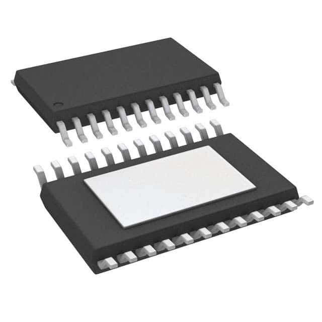
- Part No.:
- A8508GLPTR-T
- Manufacturer:
- Allegro MicroSystems
- Category:
- LED Drivers
- Package:
- 24-TSSOP (0.173", 4.40mm Width) Exposed Pad
- Datasheet:
-
 A8508GLPTR-T.pdf
- Description:
- IC LED DRIVER CTRLR PWM 24TSSOP
- Quantity:
- Payment:

- Shipping:

Inventory:1,276
Please send an inquiry. Send us your inquiry, and we will respond immediately.
Product details
Overview
A8508GLPTR-T from Allegro MicroSystems is an 8-channel fault-tolerant white LED driver IC for LCD panel backlighting, integrating a current-mode boost controller and eight individually controllable current sinks. It operates from 9–40 V input, delivers up to 150 mA per channel, supports 300–800 kHz switching frequency via FSET/SYNC pin, and includes open/short LED detection, overvoltage protection, and thermal shutdown - deployed in automotive instrument clusters and industrial HMI displays.
For engineers reviewing the A8508GLPTR-T datasheet, A8508GLPTR-T pinout, A8508GLPTR-T application, or A8508GLPTR-T equivalent, this page provides verified technical context, real-world design meaning of key specs, validated pin functions, confirmed alternative parts with documented differences, and supply guidance for legacy design support and obsolescence mitigation.
Technical Context
The A8508GLPTR-T implements a fixed-frequency current-mode boost controller with integrated gate driver to drive an external N-channel MOSFET, enabling scalable LED string voltage up to 55 V per channel. Its eight current sinks operate with 0.7% accuracy and 0.8% matching across channels, and support parallel operation (master/slave) for up to 32 strings using a single boost regulator.
It features dual-level pulse-by-pulse current limiting (soft-start and steady-state), active current sharing between strings, and configurable fault response including optional external P-FET disconnect via FAULT pin. The device uses internal bias regulation for single-supply operation and supports both PWM and analog dimming with sub-microsecond turn-on/off delays.
Key Specifications
| Parameter | Value and Actual Design Meaning |
|---|---|
| Input Voltage Range | 9–40 V - supports 12 V and 24 V automotive/industrial rails without pre-regulation |
| LED Current Accuracy | ±0.7% - ensures uniform brightness across all 8 channels in multi-string backlight systems |
| Switching Frequency | 300–800 kHz - adjustable via RFSET resistor or external sync clock; avoids AM radio band interference |
| Thermal Shutdown Threshold | 165°C - protects against sustained overload or poor PCB thermal design on 4-layer JEDEC board |
| LED Pin Short Detection | Detects <4.6 V at LEDx pins - prevents startup under short-to-GND conditions before soft start begins |
| Soft Start LED Current Gain | 44 A/A - limits inrush to ~4.5 mA per channel for 120 mA full-scale output, reducing stress on capacitors |
| FSET/SYNC Pin Function | Configurable as frequency set (via RFSET) or sync input (1.5–3.3 V push-pull) - enables EMI control and multi-IC synchronization |
Pinout & Package
The A8508GLPTR-T is housed in a 24-pin TSSOP package (LP suffix) with exposed thermal pad (PAD), optimized for high-power LED driver thermal dissipation on standard 4-layer PCBs (RθJA = 28°C/W).
| Pin | Circuit Role | Design Meaning |
|---|---|---|
| VIN | Power input | Accepts 9–40 V DC; feeds internal LDO and boost controller; UVLO threshold at 8.5 V |
| GATE | External MOSFET driver output | Drives N-channel boost switch with 6–8 V swing and 4.5 Ω pull-up/pull-down resistance |
| ISET | Current reference input | 1.000 V reference; sets LED current via RISET resistor (e.g., 9.53 kΩ → 120 mA) |
| FSET/SYNC | Frequency control / sync input | Resistor-to-ground sets fSW; external 1.5–3.3 V clock synchronizes multiple A8508s |
| LED1–LED8 | Current sink outputs | Eight independent cathode connections; each regulates current with 650 mV compliance voltage |
| FAULT | Open-drain fault indicator | Pulled low on OVP, OTP, LED short/open, or boost overcurrent; can drive external P-FET disconnect |
| EN | Enable input | Logic-high (>1.5 V) enables IC after VIN exceeds UVLO; internal 100 kΩ pull-down |
| PWM | PWM dimming control | Directly modulates LED current; 0.5–1.1 µs turn-on/off delay enables >1 kHz dimming |
Key Features
| Feature | Design Value |
|---|---|
| 8-channel current sinks with 0.7% accuracy | Enables uniform backlight luminance across large LCD panels without per-channel trimming |
| Parallel master/slave operation | One A8508GLPTR-T master controls up to three slave A8508s, scaling to 32 LED strings with one boost stage |
| Active current sharing between strings | Maintains ±0.8% matching even with mismatched LED forward voltages or thermal gradients |
| Dual-level pulse-by-pulse current limit | Soft-start limit (39 mV sense threshold) prevents inrush; steady-state limit protects external MOSFET during faults |
| LED pin short-to-GND detection | Halts startup if any LEDx pin reads <100 mV, preventing uncontrolled current flow into shorts |
Applications
| Automotive Instrument Cluster Backlight | Industrial HMI Display Backlight |
|---|---|
Use Scenario: Driving 8 independent LED strings behind TFT-LCD gauges in vehicles operating from 9–16 V battery with load dump transients. IC Role / Device Role / Timing Role: Primary LED current controller and boost regulator; manages dynamic dimming, fault isolation, and thermal safety in real time. Use Value: Fault tolerance prevents total backlight failure during single-string open/short events; wide input range eliminates need for upstream DC/DC pre-regulator. |
Use Scenario: Backlighting ruggedized 10.4" industrial display used in factory HMIs with ambient temperature ranging –40°C to +85°C. IC Role / Device Role / Timing Role: High-accuracy constant-current source with synchronized PWM dimming for flicker-free human interface operation. Use Value: 0.7% current accuracy ensures consistent color and brightness across viewing angles; thermal shutdown at 165°C prevents field failures under enclosure heat buildup. |
| Medical Diagnostic Monitor Backlight | Commercial Digital Signage Backlight |
Use Scenario: Powering high-brightness white LED arrays in Class II medical imaging monitors requiring low EMI and long-term reliability. IC Role / Device Role / Timing Role: Fault-aware LED driver with OVP, OTP, and open-LED detection - critical for safety-critical visual diagnostics. Use Value: Dual-level current limiting and automatic LED detection prevent catastrophic failure modes that could compromise diagnostic image fidelity. |
Use Scenario: Driving 8-channel edge-lit LED bars in 43" digital signage displays powered from 24 V PoE-derived supplies. IC Role / Device Role / Timing Role: Scalable LED driver supporting parallel configuration for higher string counts while maintaining single-point thermal management. Use Value: Master/slave capability allows 32-string expansion without redesign; exposed thermal pad enables conduction cooling in fanless enclosures. |
Equivalent & Alternatives
The following parts are listed as comparable options for similar LED driver applications.
| Alternative Part | Technical Difference | Application Difference | Selection Advice |
|---|---|---|---|
| A80606KEVJSR | Successor IC with enhanced efficiency, lower quiescent current (0.5 µA sleep), and updated protection logic; same 24-pin TSSOP LP package footprint. | Designed for new designs requiring extended lifecycle support; not drop-in compatible due to revised MODE/FSET timing and FAULT behavior. | Select A80606KEVJSR for new designs needing production longevity; A8508GLPTR-T remains viable only for legacy repair or obsolescence bridging. |
| LM3409QMY/NOPB | Single-channel buck-boost LED controller (not multi-channel); requires external current sinks; no integrated LED fault detection or current matching. | Suitable for custom multi-IC solutions where flexibility outweighs integration; lacks A8508's 8-channel synchronization and matching. | Choose LM3409QMY/NOPB only when designing modular, scalable drivers with discrete current paths and separate fault monitoring. |
Compared with A8508GLPTR-T, A80606KEVJSR offers improved power efficiency and lifecycle assurance but requires firmware and layout updates; LM3409QMY/NOPB provides architectural flexibility at the cost of increased BOM count, calibration effort, and absence of built-in channel matching.
Availability
A8508GLPTR-T is available at Aetrix Electronics and suitable for automotive instrument cluster backlighting, industrial HMI display backlighting, and medical diagnostic monitor backlighting requiring stable component supply despite end-of-life status.
Supply support for A8508GLPTR-T includes scheduled delivery planning, volume procurement assistance, BOM continuity management, traceable sourcing, and lifecycle availability coordination for OEM customers, industrial embedded developers, connected-device designers, and electronics production programs.
Manufacturer
Allegro MicroSystems is a U.S.-based designer of high-performance magnetic sensing and power ICs, specializing in motion control, energy-efficient power conversion, and robust automotive-grade semiconductor solutions.
The A8508 product line was developed specifically for high-reliability, multi-string LCD backlighting in harsh environments - emphasizing fault tolerance, thermal resilience, and seamless integration into automotive and industrial display subsystems.
FAQ
Is A8508GLPTR-T still in production?
No, A8508GLPTR-T is a discontinued product. Allegro MicroSystems officially ended production as of September 30, 2024. It should not be purchased for new design applications. Aetrix Electronics maintains limited legacy stock for repair and obsolescence bridging, with full traceability and documentation for each batch of A8508GLPTR-T supplied.
What is the recommended replacement for A8508GLPTR-T?
The officially recommended substitution is A80606KEVJSR, cited in Allegro's documentation for existing customer transition and new applications. While pin-compatible in the 24-pin TSSOP LP package, A80606KEVJSR introduces changes to MODE logic timing and FAULT pin behavior - requiring validation of startup sequence and fault response in the target system before migration from A8508GLPTR-T.
Can A8508GLPTR-T drive more than 8 LED strings?
Yes - A8508GLPTR-T supports master/slave parallel operation. One A8508GLPTR-T configured as master can synchronize up to three additional A8508 devices (slaves), enabling control of up to 32 LED strings while using only a single boost converter stage and shared compensation network - preserving efficiency and minimizing component count.
What thermal derating applies to A8508GLPTR-T on a 2-layer PCB?
A8508GLPTR-T's specified RθJA of 28°C/W assumes a 4-layer JEDEC-standard PCB. On a 2-layer board with identical copper area, thermal resistance increases significantly - typically by 40–60%. For continuous 120 mA/channel operation, junction temperature may exceed 150°C above 70°C ambient unless additional thermal vias, copper pour, or heatsinking are applied. Derate maximum LED current by ≥25% on 2-layer layouts.
Does A8508GLPTR-T support analog dimming via DAC?
Yes, A8508GLPTR-T supports analog dimming by injecting a voltage onto the ISET pin or ground side of the RISET resistor. The ISET pin accepts 34–130 µA, corresponding to 0–100% LED current. Using a DAC with 1.00 V reference, output voltages below 1.00 V increase LED current; above 1.00 V reduce it - enabling precise grayscale control without PWM-induced flicker in A8508GLPTR-T systems.
A8508GLPTR-T Specifications
- Product attributes
- Attribute value
- Manufacturer:
- Allegro MicroSystems
- Series:
- -
- Package/Case:
- 24-TSSOP (0.173", 4.40mm Width) Exposed Pad
- Packaging:
- Tape & Reel (TR)
- Product Status:
- Obsolete
- Type:
- DC DC Controller
- Topology:
- SEPIC, Step-Up (Boost)
- Internal Switch(s):
- No
- Number of Outputs:
- 8
- Voltage - Supply (Min):
- 9V
- Voltage - Supply (Max):
- 40V
- Voltage - Output:
- -
- Current - Output / Channel:
- -
- Frequency:
- 300kHz ~ 800kHz
- Dimming:
- Analog, PWM
- Applications:
- Backlight
- Operating Temperature:
- -40°C ~ 105°C (TA)
- Grade:
- -
- Qualification:
- -
- Mounting Type:
- Surface Mount
- Supplier Device Package:
- 24-TSSOP-EP
A8508GLPTR-T FAQ
1.How can I place an order for A8508GLPTR-T through Aetrix?
Please submit a Request for Quotation (RFQ) for A8508GLPTR-T on Aetrix. Our sales agent will provide a competitive quotation and guide you through the order confirmation once you accept the terms.
2.Are the price and stock information for A8508GLPTR-T reliable?
The price and inventory of A8508GLPTR-T are updated periodically and may fluctuate due to market conditions. Stock and pricing data are typically refreshed every 24 hours. Quotation validity for A8508GLPTR-T is usually 5 days.
3.What payment methods are accepted for A8508GLPTR-T?
We accept Wire Transfer, PayPal, Credit Card, Western Union, MoneyGram, and Escrow for A8508GLPTR-T transactions.
Note: Certain payment methods may incur a processing fee.
4.How is shipping managed for A8508GLPTR-T?
A8508GLPTR-T orders can be shipped via leading logistics carriers, including DHL, UPS, FedEx, TNT, or Registered Mail.
Once your A8508GLPTR-T order is processed, you will receive an email with the shipment details and tracking number.
Note: Tracking information may take up to 24 hours to appear. Express delivery typically takes 3–5 business days.
5.How can I obtain technical support or documentation for A8508GLPTR-T?
For technical support, including A8508GLPTR-T datasheets, pinout diagrams, or application guidance, please contact our engineering support team. They can provide detailed documentation and assistance for your A8508GLPTR-T requirements.
6.How does Aetrix verify that A8508GLPTR-T is sourced from the original manufacturer or authorized distributors?
All A8508GLPTR-T products on Aetrix are procured from qualified distributors and authorized channels. Our dedicated quality assurance team conducts strict verification, including traceability checks and, if necessary, third-party testing. This ensures that A8508GLPTR-T meets industry standards.
7.What is the process for return or replacement of A8508GLPTR-T?
All A8508GLPTR-T units undergo pre-shipment inspection (PSI). If there is an issue with A8508GLPTR-T, returns or replacements are accepted under the following conditions:
1.Quantity discrepancies, incorrect items, or visible external defects (such as breakage or corrosion), acknowledged by Aetrix.
2.The issue is reported within 90 days of delivery.
3.The A8508GLPTR-T part is unused and in its original packaging.
Return procedure for A8508GLPTR-T:
1.Submit a request within 90 days.
2.Obtain a Return Material Authorization (RMA) from Aetrix.
A8508GLPTR-T Tags

-
BCR402RE6327HTSA1
Infineon Technologies

-
BCR430UXTSA2
Infineon Technologies

-
BCR420UE6433HTMA1
Infineon Technologies
-
BCR420UE6327HTSA1
Infineon Technologies
-
BCR421UE6327HTSA1
Infineon Technologies

-
LYT1604D-TL
Power Integrations

-
HV9910CLG-G
Microchip Technology

-
CL2N8-G
Microchip Technology

-
BCR420UW6-7
Diodes Incorporated
-
BCR421UW6-7
Diodes Incorporated

-
BCR420UFD-7
Diodes Incorporated
-
BCR421UFD-7
Diodes Incorporated
Tech Hub

A practical engineering and sourcing framework covering lifecycle verification, lifetime-buy calculations, replacement qualification, supplier checks and counterfeit-risk controls.

TTL and CMOS logic families differ in thresholds, loading, output drive, power and timing. This engineering guide compares 74HC and 74HCT, calculates noise margins and checks 3.3 V/5 V compatibility.

A practical engineering guide to 3.3V and 5V logic compatibility, input thresholds, resistor dividers, translator ICs, MOSFET level shifting, I2C pull-ups, timing limits and power-sequencing risks.

The 74HC595 uses push-pull logic outputs, while the TPIC6B595 uses 50 V open-drain DMOS sinks for higher-power loads. This guide compares timing, current limits, 3.3 V interfacing, load wiring, thermal…

The 74HC595 converts serial data into eight stable parallel outputs. This guide covers pin functions, shift and storage timing, OE and MR behavior, drive-current limits, cascading, voltage compatibilit…

A technical comparison of level-sensitive latches and edge-triggered flip-flops, covering timing windows, setup and hold limits, master–slave operation, time borrowing, race-through, HDL inference and…

A D latch stores one bit while Enable controls when data can pass. This reference covers gate-level operation, truth tables, transparency, setup and hold timing, LE versus OE, common ICs and practical …

An SR latch stores one bit through cross-coupled feedback. This engineering reference covers NOR and NAND implementations, truth tables, forbidden-state recovery, gated operation, switch debouncing, fa…

Latch circuits retain one bit through feedback. This technical reference covers SR and D latches, truth tables, transparency, timing limits, latch-versus-flip-flop behavior, applications and common log…

An engineering guide to LED driver operation, constant-current and constant-voltage outputs, linear and switching topologies, dimming, IC selection, calculations, replacement compatibility, and fault c…


